

Page 1
VIESMANN
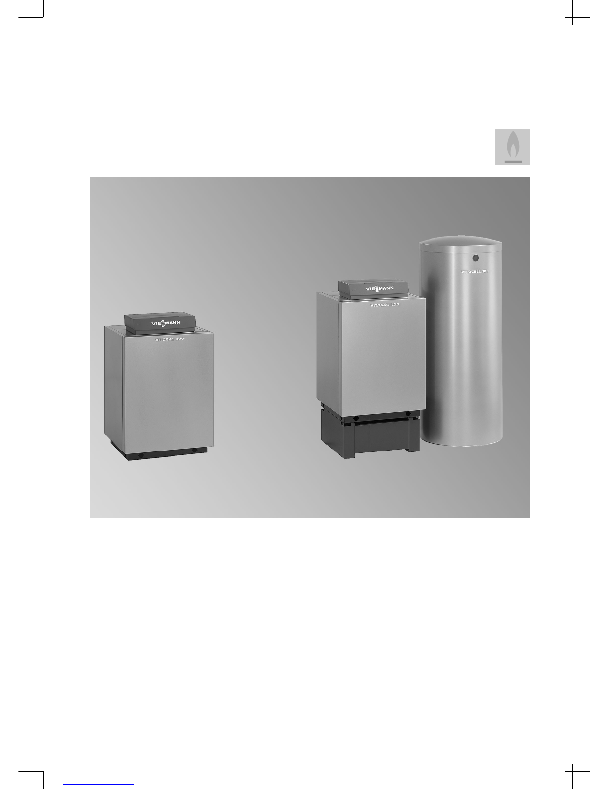
VITOGAS
Low temperature gas boiler
11 to 60 kW
VITOGAS 200-F Type GS2
Low temperature gas boilers, 11 to 60 kW
■
For modulating boiler water temperature
■
With premix burner for natural gas and LPG
■
Fully automatic
■
Permissible operating pressure 3 bar
■
Product ID: CE-0085 AS 0297
VITOGAS 100-F Type GS1D
Low temperature gas boilers, 29 to 60 kW
■
For modulating boiler water temperature
■
With partially pre-mixing burner for natural gas and LPG
■
Fully automatic
■
Permissible operating pressure 3 bar
■
Product ID: CE-0085 AS 0297
5822 428 GB 5/2010
Technical guide
Page 2

Index
1. Product information 1. 1 Vitogas 200-F ............................................................................................................. 4
■ Benefits ................................................................................................................... 4
■ Delivered condition ................................................................................................. 4
■ Approved quality ..................................................................................................... 5
1. 2 Operating conditions ................................................................................................... 5
1. 3 Specification ............................................................................................................... 6
■ Installation ............................................................................................................... 9
2. Vitogas 100-F 2. 1 Product description ..................................................................................................... 10
■ Benefits ................................................................................................................... 10
■ Delivered condition ................................................................................................. 10
■ Approved quality ..................................................................................................... 10
2. 2 Operating conditions ................................................................................................... 11
2. 3 Specification ............................................................................................................... 12
■ Installation ............................................................................................................... 14
3. DHW cylinder 3. 1 Specification Vitocell 100-V, type CVA ....................................................................... 17
■ Delivered condition ................................................................................................. 22
3. 2 Specification Vitocell 300-V, type EVA ....................................................................... 23
■ Delivered condition ................................................................................................. 26
3. 3 Specification Vitocell 100-H, type CHA ....................................................................... 27
■ Delivered condition ................................................................................................. 29
3. 4 Specification Vitocell 300-H, type EHA ....................................................................... 30
■ Delivered condition ................................................................................................. 33
3. 5 DHW cylinder connection on the DHW side ............................................................... 34
4. Installation accessories 4. 1 Accessories for connecting DHW cylinder to boiler .................................................... 34
■ System connections with Vitocell ............................................................................ 34
■ Safety assembly to DIN 1988 ................................................................................. 35
4. 2 Accessories for heating circuits .................................................................................. 35
■ Divicon heating circuit distributor ............................................................................ 35
4. 3 Boiler accessories ....................................................................................................... 44
■ Four-way mixer ....................................................................................................... 44
■ Safety equipment block ........................................................................................... 44
■ Plinth for Vitogas 200-F .......................................................................................... 44
■ Plinth for Vitogas 100-F .......................................................................................... 44
■ Flue gas monitoring sensor ..................................................................................... 45
5. Design information 5. 1 Selection of rated output ............................................................................................. 45
5. 2 System design ............................................................................................................ 45
5. 3 Flue system ................................................................................................................ 45
5. 4 Safety equipment ........................................................................................................ 45
5. 5 Thermal safety shut-off valve ...................................................................................... 45
5. 6 Heating circuits ........................................................................................................... 45
5. 7 Plastic pipework for radiators ...................................................................................... 45
5. 8 Additional requirements when installing boilers for LPG operation in rooms below
ground level ................................................................................................................ 46
5. 9 Flue gas monitoring device ......................................................................................... 46
5.10 Low water indicator ..................................................................................................... 46
5.11 System water quality ................................................................................................... 46
6. Control units 6. 1 Overview of control unit types ..................................................................................... 46
■ Vitotronic 100, type KC3 ......................................................................................... 46
■ Vitotronic 100, type KC4 ......................................................................................... 47
■ Vitotronic 150, type KB2 ......................................................................................... 47
■ Vitotronic 200, type KW4 ........................................................................................ 47
■ Vitotronic 200, type KW5 ........................................................................................ 48
6. 2 Components in the delivered condition ....................................................................... 48
■ Allocation to control unit types ................................................................................ 48
■ Boiler water temperature sensor ............................................................................. 48
■ Cylinder temperature sensor ................................................................................... 48
■ Outside temperature sensor ................................................................................... 48
6. 3 Vitotronic 100, type KC3, part no. 7186 582 ............................................................... 49
■ Specification ............................................................................................................ 49
■ Delivered condition ................................................................................................. 49
6. 4 Vitotronic 100, type KC4, part no. 7186 569 ............................................................... 49
■ Specification ............................................................................................................ 49
■ Delivered condition ................................................................................................. 50
Index
2
VIESMANN
VITOGAS
5822 428 GB
Page 3

6. 5 Vitotronic 150, type KB2, part no. 7186 570 ............................................................... 50
■ Specification ............................................................................................................ 50
■ Delivered condition ................................................................................................. 51
6. 6 Vitotronic 200, type KW4, part no. 7186 571 .............................................................. 51
■ Specification ............................................................................................................ 51
■ Delivered condition ................................................................................................. 53
6. 7 Vitotronic 200, type KW5, part no. 7186 317 .............................................................. 53
■ Specification ............................................................................................................ 53
■ Delivered condition ................................................................................................. 55
6. 8 Control unit accessories ............................................................................................. 55
■ Allocation of accessories according to control unit type ......................................... 55
■ Extension kit for one heating circuit with mixer ....................................................... 55
■ Extension kit for one heating circuit with mixer in conjunction with the Divicon heat-
ing circuit distributor ................................................................................................ 56
■ Contact temperature sensor ................................................................................... 56
■ Immersion thermostat ............................................................................................. 56
■ Contact thermostat .................................................................................................. 57
■ Vitotrol 100, type UTDB .......................................................................................... 57
■ Vitotrol 100, type UTDB-RF .................................................................................... 58
■ Notes regarding room temperature hook-up (RS function) for remote control
units ........................................................................................................................ 58
■ Information regarding the Vitotrol 200 and 300 ....................................................... 58
■ Vitotrol 200 .............................................................................................................. 59
■ Vitotrol 300 .............................................................................................................. 59
■ Room temperature sensor ...................................................................................... 60
■ KM BUS distributor ................................................................................................. 60
■ Flue gas temperature sensor .................................................................................. 60
■ Radio clock receiver ................................................................................................ 61
■ Function extension 0–10 V ..................................................................................... 61
■ Functions in connection with the function extension 0 – 10 V (accessory) ............. 61
■ External extension H5 ............................................................................................. 61
■ Vitocom 100, type GSM .......................................................................................... 62
■ Control module V .................................................................................................... 62
7. Keyword index .............................................................................................................................................. 63
Index
(cont.)
VITOGAS
VIESMANN
3
5822 428 GB
Page 4
1.1 Vitogas 200-F
Benefits
■ Standard seasonal efficiency [to DIN]: 84 % (Hs) / 93 % (Hi)
■ High operational reliability and a long service life because of heating
surfaces made from special cast iron with lamellar graphite and low
heating surface load
■ Clean combustion because of single stage atmospheric premix
burner
■ Performs better than required for the "Blue Angel" certificate of environmental excellence and the Swiss Clean Air Act
■ Low energy consumption through modulating boiler water temperature when the outside temperature rises
■ Highly reliable and gentle low-noise ignition through intermittent ignition system
■ Compact dimensions ensure easy installation in a boiler or utility
room
■ May be combined with a DHW cylinder of matching design
■ Easy installation because of low weight and compact design
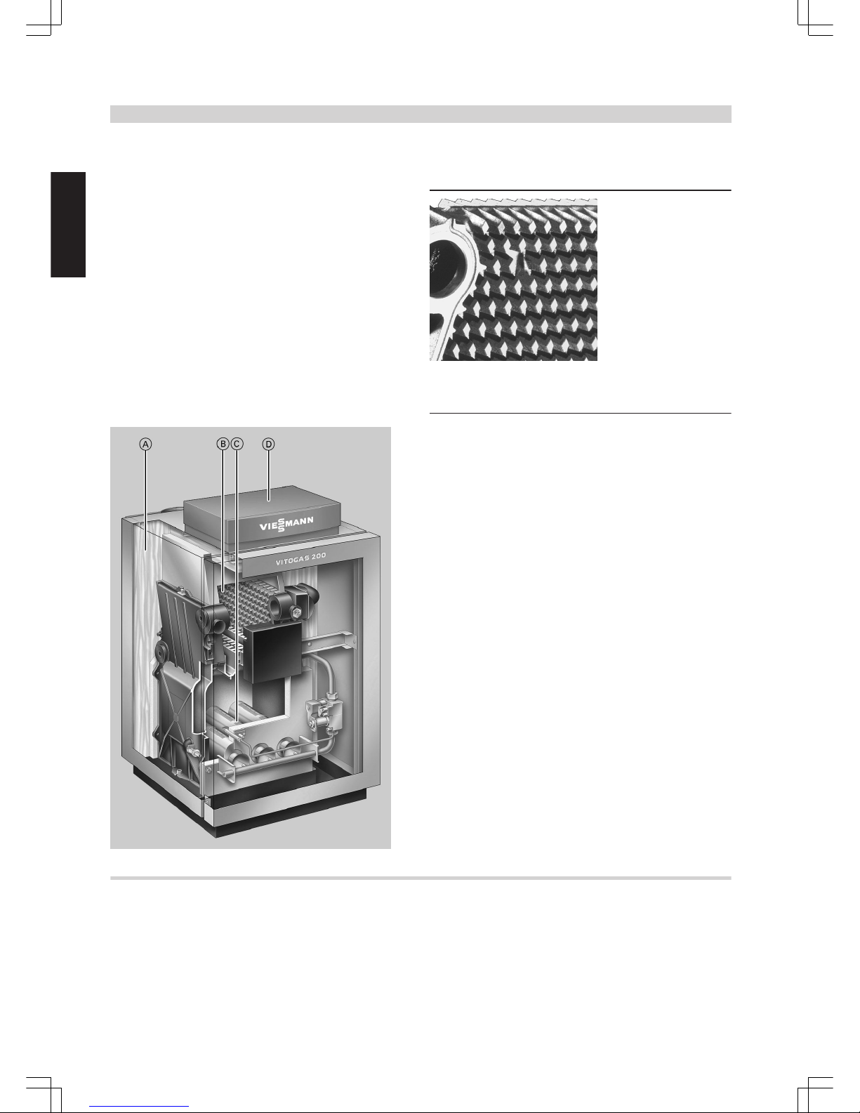
Heating surface made from special cast iron for high operational
reliability and a long service life
A
Highly effective thermal insulation
B
Heating surfaces made from special cast iron
C
Atmospheric stainless steel premix burner
D
Digital Vitotronic boiler control unit
Delivered condition
■ Boiler with fitted thermal insulation and atmospheric premix burner
for natural gas and LPG according to DVGW Code of Practice G 260
[Germany] or local regulations
■ The boiler is factory-fitted for natural gas E
■ A conversion kit for natural gas LL is supplied to order. A conversion
kit for LPG is available separately. The conversion kit for LPG
includes a gas pressure limiter.
■ 1 product pack (boiler coding card and Vitogas 200-F technical documentation)
■ 1 carton containing the boiler control unit and 1 bag with technical
documentation
■ Possible boiler/DHW cylinder combinations, see pricelist
■ Carrying handles are available for easier transportation, see pricelist
Product information
4
VIESMANN
VITOGAS
1
5822 428 GB
Page 5
Approved quality
CE designation according to current EC Directives
Qualitätsmarke der ÖVGW gemäß Gütezeichenverordnung
1942 DRGBl. I für Erzeugnisse des Gas- und Wasserfachs
Meets the requirements of the "Blue Angel" certificate of environmental
excellence to RAL UZ 39
1.2 Operating conditions
Requirements Implementation
1. Heating water flow rate none —
2. Boiler return temperature
(minimum value)
35 ºC Installation of an efficient return tempera-
ture raising facility (e.g. through 4-way
mixer and minimum limit and/or return
temperature raising pump)
3. Low-end boiler water temperature
(also for frost protection)
35 ºC Through the Viessmann control unit
(standard delivery)
Product information
(cont.)
VITOGAS
VIESMANN
5
5822 428 GB
1
Page 6

1.3 Specification
Gas boiler, type B11/B
11 BS
, category II
2ELL3 P
Rated output kW 11 15 18 22 29 35 42 48 60
Rated heat input kW 12.1 16.6 19.9 24.3 32.0 38.6 46.4 53.0 66.2
Heating surface
m
2
1.04 1.04 1.51 1.51 1.99 2.46 2.93 3.40 4.35
U-value of thermal insulation
W/m2 K
0.45 0.45 0.45 0.45 0.45 0.45 0.45 0.45 0.45
Product ID CE 0085 AS 0297
Gas supply pressure (nominal pres-
sure)
Natural gas mbar 20 20 20 20 20 20 20 20 20
LPG mbar 50 50 50 50 50 50 50 50 50
Max. permissible gas supply pressure
Natural gas mbar 25 25 25 25 25 25 25 25 25
LPG mbar 57.5 57.5 57.5 57.5 57.5 57.5 57.5 57.5 57.5
Total dimensions (height is given
incl. 13 mm adjustable feet)
Length mm 580 580 580 580 580 580 580 580 580
Total length c mm 760 760 760 760 760 780 780 780 780
Width a mm 446 446 526 526 596 706 796 886 1076
Total width b mm 500 500 580 580 650 760 850 940 1130
Height without control unit mm 788 788 788 788 788 788 788 788 788
Height with control unit mm 890 890 890 890 890 890 890 890 890
Height with flue pipe bend d mm 950 980 1005 1005 1025 1025 1025 1095 1095
Plinth height mm 250 250 250 250 250 250 250 250 250
Total weight
Boiler with thermal insulation, burner
and boiler control unit
kg 101 101 124 124 148 170 194 218 264
Content boiler water litres 7.6 7.6 9.7 9.7 11.7 13.8 15.9 17.9 21.9
Permiss. operating pressure bar 3 3 3 3 3 3 3 3 3
Boiler connections
Boiler flow and return G 1½ 1½ 1½ 1½ 1½ 1½ 1½ 1½ 1½
Safety flow G 1½ 1½ 1½ 1½ 1½ 1½ 1½ 1½ 1½
Drain R ¾ ¾ ¾ ¾ ¾ ¾ ¾ ¾ ¾
Gas connection R ½ ½ ½ ½ ½ ½ ½ ½ ½
Connection values
in relation to the max. load
Natural gas E
m3/h
1.28 1.76 2.11 2.57 3.39 4.09 4.91 5.61 7.01
Natural gas LL
m3/h
1.49 2.04 2.45 2.99 3.94 4.75 5.71 6.52 8.15
LPG kg/h 0.95 1.30 1.56 1.90 2.50 3.02 3.62 4.14 5.17
Flue gas parameters
(calculation values for sizing the flue
gas system to EN 13384)
Flue gas temperatures
(gross values, measured at 20 °C
combustion air temperature)
50 °C boiler water temperature
(actual values are significant for the
sizing of the flue system)
°C 80 95 90 97 102 101 114 114 109
80 °C boiler water temperature
(actual values for determining the
application range of flue gas lines with
max. permissible operating temperatures)
°C 90 104 102 106 118 113 130 130 122
Mass flow rate
Natural gas kg/h 32 48 58 73 92 107 105 127 160
at CO2 content % 5.5 5.0 5.0 4.8 5.0 5.2 6.5 6.1 6.0
LPG kg/h 30 48 54 67 84 95 101 126 153
at CO2 content % 6.6 5.6 6.0 5.9 6.2 6.7 7.6 6.9 7.1
Required draught Pa 3 3 3 3 3 3 3 3 3
mbar 0.03 0.03 0.03 0.03 0.03 0.03 0.03 0.03 0.03
Flue gas connection Ø mm 90 110 130 130 150 150 150 180 180
Seasonal efficiency [to DIN]
TV/TR = 75/60 °C
% 84 (Hs)/93 (Hi)
Standby heat loss at 60 °C boiler
water temperature
% 1.9 1.5 1.5 1.2 1.1 1.0 0.9 0.8 0.8
Product information
(cont.)
6
VIESMANN
VITOGAS
1
5822 428 GB
Page 7
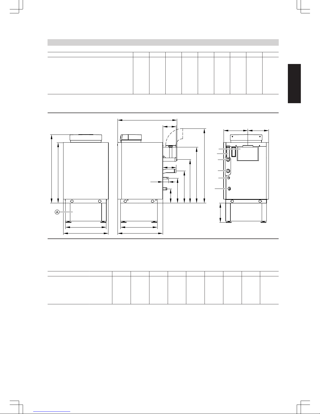
Rated output kW 11 15 18 22 29 35 42 48 60
Further connection dimensions
Internal diameter of pipe to expansion
vessel
DN 15 15 15 20 20 20 20 20 20
R ½ ½ ½ ¾ ¾ ¾ ¾ ¾ ¾
Safety valve DN 15 15 15 15 15 15 15 15 15
R ½ ½ ½ ½ ½ ½ ½ ½ ¾
Blow-off line DN 20 20 20 20 20 20 20 20 25
R ¾ ¾ ¾ ¾ ¾ ¾ ¾ ¾ 1
Note
If the gas supply pressure exceeds the maximum permitted value, install a separate gas pressure governor upstream of the system.
fe
SSI
KV
KR
GA
E
d
179
316
409
554
716
173
173
250
580
457
b
a
775
877
c
78
SV
A
Subframe (accessory)
E Drain and diaphragm expansion vessel
GA Gas connection
KR Boiler return
KV Boiler flow
SSI Draught hood
SV Safety flow
Dimensions
Rated output kW 11 15 18 22 29 35 42 48 60
a mm 446 446 526 526 596 706 796 886 1076
b mm 500 500 580 580 650 760 850 940 1130
c mm 760 760 760 760 760 780 780 780 780
d mm 937 967 992 992 1012 1012 1012 1082 1082
e mm 266 266 312 312 359 403 449 495 586
f mm 234 234 268 268 291 357 401 445 544
Product information
(cont.)
VITOGAS
VIESMANN
7
5822 428 GB
1
Page 8
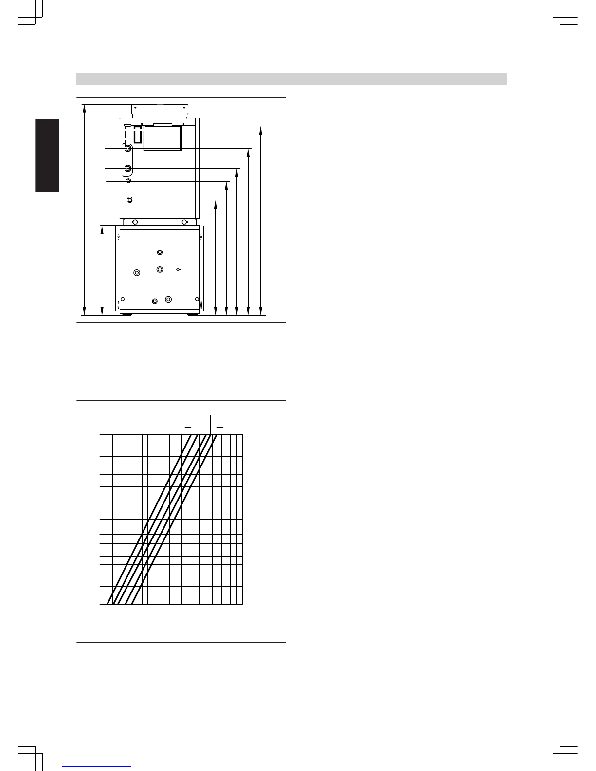
833
1370
1208
1063
970
654
1531
E
GA
KR
KV
SSI
B
SV
B
For Vitocell 100-H/300-H, see pages 27 and 30. Only possible for those combinations specified in the pricelist.
E Drain and diaphragm expansion vessel
GA Gas connection
KR Boiler return
KV Boiler flow
SSI Draught hood
SV Safety flow
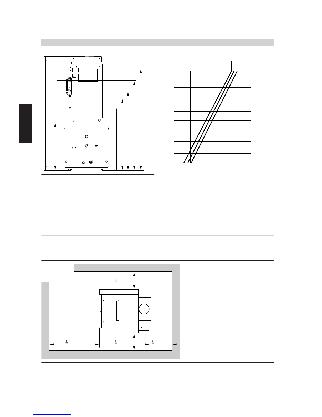
Pressure drop (primary circuit)
The Vitogas 200-F is only suitable for fully pumped hot water heating
systems.
1
2
3
4
5
6
8
10
20
30
40
50
300
400
500
600
800
1000
2000
3000
4000
5000
6000
8000
Pressure drop in mbar
Throughput in l/h
C
EA
B D
A
Rated output 11 and 15 kW
B
Rated output 18 and 22 kW
C
Rated output 29 kW
D
Rated output 35 and 42 kW
E
Rated output 48 and 60 kW
Product information
(cont.)
8
VIESMANN
VITOGAS
1
5822 428 GB
Page 9
Installation
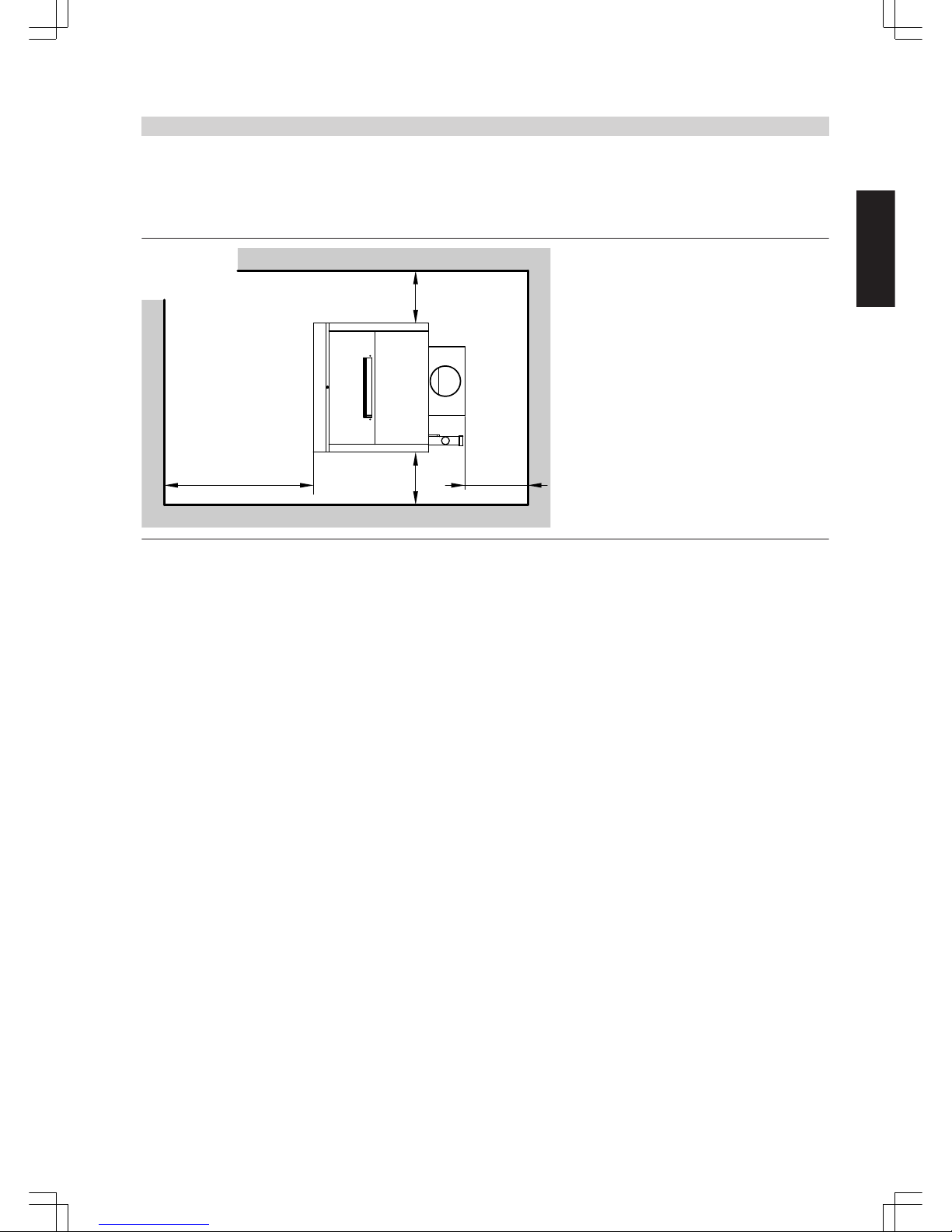
Minimum clearances
Observe the given dimensions to ensure easy installation and maintenance.
700 mm
250 mm
250 mm
≥
250 mm
≥
≥
≥
Installation
■ Avoid air contamination through halogenated hydrocarbons (e.g. as
in sprays, paints, solvents and cleaning agents)
■ Avoid very dusty conditions
■ Avoid high levels of humidity
■ Prevent freezing and ensure good ventilation
Otherwise, the system may suffer faults and damage.
In rooms where air contamination through halogenated hydrocar-
bons may occur, install the boiler only if adequate measures can be
taken to provide a supply of uncontaminated combustion air.
Product information
(cont.)
VITOGAS
VIESMANN
9
5822 428 GB
1
Page 10
2.1 Product description
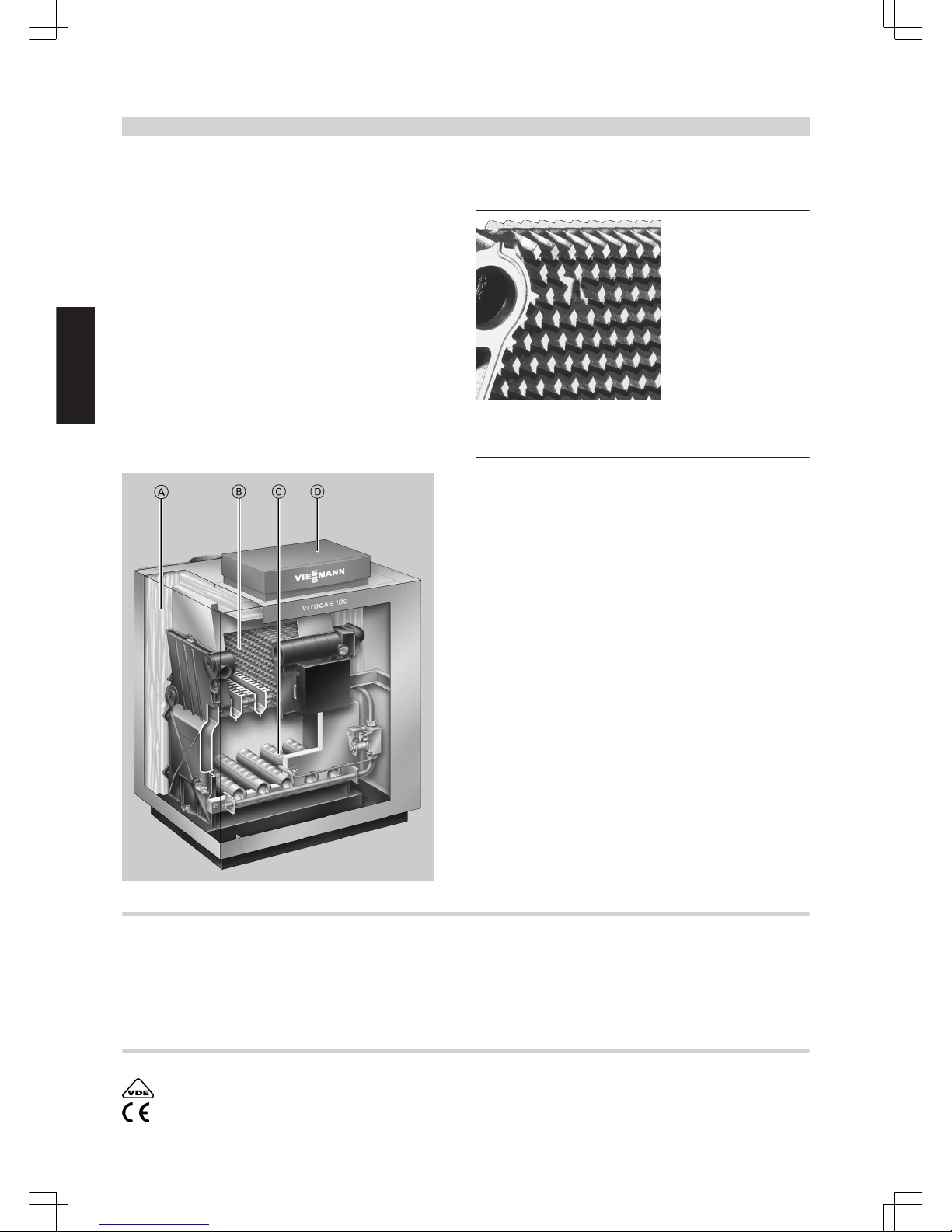
Benefits
■ Standard seasonal efficiency [to DIN]: 83 % (Hs) / 92 % (Hi)
■ Atmospheric gas boiler with partially pre-mixing burner
■ High operational reliability with severely fluctuating mains pressures
and mains power fluctuations, plus a long service life because of
heating surfaces made from special cast iron with lamellar graphite
and low heating surface load
■ Partially pre-mixing stainless steel rod burner with Renox system
(may be retrofitted) for reducing NOx emissions
■ Highly reliable and gentle low-noise ignition through intermittent ignition system
■ With factory-fitted gas pressure limiter for automatic restart after gas
mains failure
■ Easy installation because of low weight and compact design
Heating surface made from special cast iron for high operational
reliability and a long service life
A
Highly effective thermal insulation
B
Heating surfaces made from special cast iron
C
Partially pre-mixing stainless steel rod burner
D
Digital Vitotronic boiler control unit
Delivered condition
■ Boiler with fitted thermal insulation and atmospheric premix burner
for natural gas and LPG according to DVGW Code of Practice G 260
or local regulations
■ The boiler is factory-fitted for natural gas E
■ A conversion kit for natural gas LL is supplied to order. A conversion
kit for LPG is available separately. The conversion kit for LPG
includes a gas pressure limiter.
■ 1 product pack (boiler coding card and Vitogas 100-F technical documentation)
■ 1 carton containing the boiler control unit and 1 bag with technical
documentation
■ Possible boiler/DHW cylinder combinations, see pricelist
■ Carrying handles are available for easier transportation, see pricelist
Approved quality
VDE assessment with production monitoring
CE designation according to current EC Directives
Vitogas 100-F
10
VIESMANN
VITOGAS
2
5822 428 GB
Page 11

2.2 Operating conditions
Requirements Implementation
1. Heating water flow rate none —
2. Boiler return temperature
(minimum value)
35 ºC Installation of an efficient return tempera-
ture raising facility (e.g. through 4-way
mixer and minimum limit and/or return
temperature raising pump)
3. Low-end boiler water temperature
(also for frost protection)
35 ºC Through the Viessmann control unit
(standard delivery)
Vitogas 100-F
(cont.)
VITOGAS
VIESMANN
11
5822 428 GB
2
Page 12

2.3 Specification
Gas boiler, type B11/B
11 BS
, category II
2ELL3 P
Rated output kW 29 35 42 48 60
Rated heat input kW 32.0 38.6 46.4 53.0 66.2
Heating surface
m
2
1.99 2.46 2.93 3.40 4.35
U-value of thermal insulation
W/m2 K
0.45 0.45 0.45 0.45 0.45
Product ID CE-0085 AS 0297
Gas supply pressure (nominal pressure)
Natural gas mbar 20 20 20 20 20
LPG mbar 30 30 30 30 30
Max. permissible gas supply pressure
Natural gas mbar 25 25 25 25 25
LPG mbar 57.5 57.5 57.5 57.5 57.5
Total dimensions (height is given incl. 13 mm adjustable feet)
Length mm 580 580 580 580 580
Total length c mm 760 780 780 780 780
Width a mm 596 706 796 886 1076
Total width b mm 650 760 850 940 1130
Height without control unit mm 788 788 788 788 788
Height with control unit mm 890 890 890 890 890
Height with flue pipe bend d mm 1025 1025 1025 1095 1095
Plinth height mm 250 250 250 250 250
Total weight
Boiler with thermal insulation, burner and boiler control
unit
kg 142 164 188 211 257
Content boiler water litres 11.7 13.8 15.9 17.9 21.9
Permiss. operating pressure bar 3 3 3 3 3
Boiler connections
Boiler flow and return G 1½ 1½ 1½ 1½ 1½
Drain R ¾ ¾ ¾ ¾ ¾
Gas connection R ½ ½ ½ ½ ½
Connection values
in relation to the max. load
Natural gas E
m3/h
3.39 4.09 4.91 5.61 7.01
Natural gas LL
m3/h
3.94 4.75 5.71 6.52 8.15
LPG kg/h 2.50 3.02 3.62 4.14 5.17
Flue gas parameters
(calculation values for sizing the flue gas system to
EN 13384)
Flue gas temperatures
(gross values, measured at 20 °C combustion air temperature)
50 °C boiler water temperature
(actual values are significant for the sizing of the flue
system)
°C 102 101 114 114 109
80 °C boiler water temperature
(actual values for determining the application range of
flue gas lines with max. permissible operating temperatures)
°C 118 113 130 130 122
Mass flow rate
Natural gas kg/h 92 107 105 127 160
at CO2 content % 5.0 5.2 6.5 6.1 6.0
LPG kg/h 84 95 101 126 153
at CO2 content % 6.2 6.7 7.6 6.9 7.1
Required draught Pa 3 3 3 3 3
mbar 0.03 0.03 0.03 0.03 0.03
Flue gas connection Ø mm 150 150 150 180 180
Seasonal efficiency [to DIN]
TV/TR = 75/60 °C
% 83 (Hs)/92 (Hi)
Standby heat loss at 60 °C boiler water temperature % 1.1 1.0 0.9 0.8 0.8
Further connection dimensions
Internal diameter of pipe to expansion vessel DN 20 20 20 20 20
R ¾ ¾ ¾ ¾ ¾
Safety valve DN 15 15 15 15 15
R ½ ½ ½ ½ ¾
Blow-off line DN 20 20 20 20 25
R ¾ ¾ ¾ ¾ 1
Vitogas 100-F
(cont.)
12
VIESMANN
VITOGAS
2
5822 428 GB
Page 13
Note
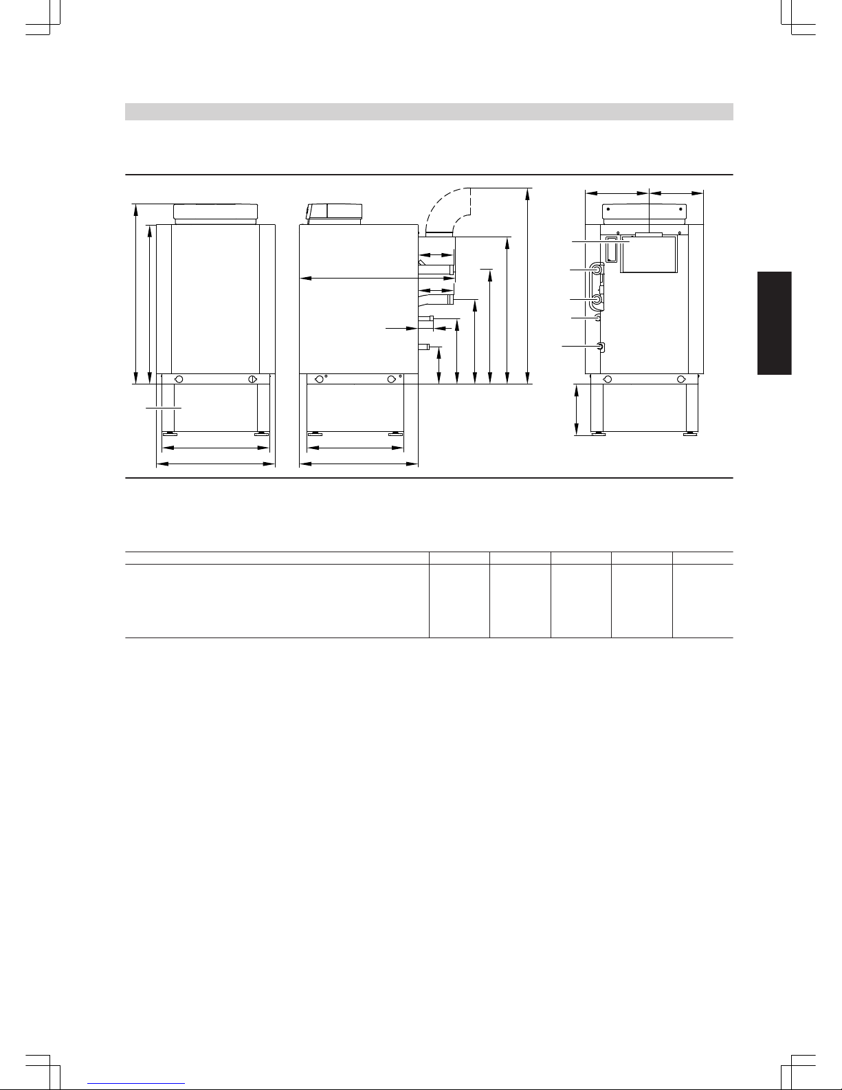
If the gas supply pressure exceeds the maximum permitted value, install a separate gas pressure governor upstream of the system.
fe
SSI
KV
KR
GA
E
d
179
316
409
554
716
173
173
250
580
457
b
a
775
877
A
c
78
A
Subframe (accessory)
E Drain and diaphragm expansion vessel
GA Gas connection
KR Boiler return
KV Boiler flow
SSI Draught hood
Dimensions
Rated output kW 29 35 42 48 60
a mm 596 706 796 886 1076
b mm 650 760 850 940 1130
c mm 760 780 780 780 780
d mm 1012 1012 1012 1082 1082
e mm 359 403 449 495 586
f mm 291 357 401 445 544
Vitogas 100-F
(cont.)
VITOGAS
VIESMANN
13
5822 428 GB
2
Page 14
833
1370
1208
1063
970
654
1531
E
GA
KR
KV
SSI
B
B
For Vitocell 100-H/300-H, see pages 27 and 30. Only possi-
ble for those combinations specified in the pricelist.
E Drain and diaphragm expansion vessel
GA Gas connection
KR Boiler return
KV Boiler flow
SSI Draught hood
Pressure drop (primary circuit)
The Vitogas 100-F is only suitable for fully pumped hot water heating
systems.
B
A
1
2
3
4
5
6
8
10
20
30
40
50
300
400
500
600
800
1000
2000
3000
4000
5000
6000
8000
Pressure drop in mbar
Flow rate in m³/h
C
A
Rated output 29 kW
B
Rated output 35 and 42 kW
C
Rated output 48 and 60 kW
Installation
Minimum clearances
Observe the given dimensions to ensure easy installation and maintenance.
700 mm
250 mm
250 mm 250 mm
Vitogas 100-F
(cont.)
14
VIESMANN
VITOGAS
2
5822 428 GB
Page 15

Installation
■ Avoid air contamination through halogenated hydrocarbons (e.g. as
in sprays, paints, solvents and cleaning agents)
■ Avoid very dusty conditions
■ Avoid high levels of humidity
■ Prevent freezing and ensure good ventilation
Otherwise, the system may suffer faults and damage.
In rooms where air contamination through halogenated hydrocar-
bons may occur, install the boiler only if adequate measures can be
taken to provide a supply of uncontaminated combustion air.
Vitogas 100-F
(cont.)
VITOGAS
VIESMANN
15
5822 428 GB
2
Page 16

Listed below are the specifications of the DHW cylinders that require
system connections to the boiler (see Viessmann pricelist).
For DHW cylinders with a cylinder capacity greater than 500 l, cylinder
banks and further DHW cylinders from the Viessmann pricelist, the
connecting lines must be set on site.
DHW cylinder
16
VIESMANN
VITOGAS
3
5822 428 GB
Page 17

3.1 Specification Vitocell 100-V, type CVA
For DHW heating in conjunction with boilers and district heating sys-
tems, as option with electric heater as accessory for DHW cylinders
with 300 and 500 l capacity.
Suitable for the following systems:
■ DHW temperatures up to 95 °C
■ Heating water flow temperature up to 160 °C
■ Operating pressure on the heating water side up to 25 bar
■ Operating pressure on the DHW side up to 10 bar
Capacity l 160 200 300 500 750 1000
DIN reg. no. 0241/06–13 MC/E
Continuous output
for DHW heating from 10 to 45 °C
and a heating water flow temperature of ... at the heating water
throughput stated below
90 °C kW 40 40 53 70 123 136
l/h 982 982 1302 1720 3022 3341
80 °C kW 32 32 44 58 99 111
l/h 786 786 1081 1425 2432 2725
70 °C kW 25 25 33 45 75 86
l/h 614 614 811 1106 1843 2113
60 °C kW 17 17 23 32 53 59
l/h 417 417 565 786 1302 1450
50 °C kW 9 9 18 24 28 33
l/h 221 221 442 589 688 810
Continuous output
for DHW heating from 10 to 60 °C
and a heating water flow temperature of ... at the heating water
throughput stated below
90 °C kW 36 36 45 53 102 121
l/h 619 619 774 911 1754 2081
80 °C kW 28 28 34 44 77 91
l/h 482 482 584 756 1324 1565
70 °C kW 19 19 23 33 53 61
l/h 327 327 395 567 912 1050
Heating water flow rate for the stated continuous outputs
m3/h
3.0 3.0 3.0 3.0 5.0 5.0
Standby heat loss q
BS
at a temp. differential of 45 K (actual value acc.
to DIN 4753-8.
500 l: Standard parameter to DIN V 18599)
kWh/
24 h
1.50 1.70 2.20 3.20 3.70 4.30
Thermal insulation Rigid PUR foam Flexible polyurethane foam
Dimensions
Length (7)
– incl. thermal insulation a mm 581 581 633 850 960 1060
– excl. thermal insulation mm — — — 650 750 850
Width
– incl. thermal insulation b mm 608 608 705 898 1046 1144
– excl. thermal insulation mm — — — 837 947 1047
Height
– incl. thermal insulation c mm 1189 1409 1746 1955 2100 2160
– excl. thermal insulation mm — — — 1844 2005 2060
Height of unit when tilted
– incl. thermal insulation mm 1260 1460 1792 — — —
– excl. thermal insulation mm — — — 1860 2050 2100
Installation height mm — — — 2045 2190 2250
Weight including thermal insulation kg 86 97 151 181 295 367
Heating water content l 5.5 5.5 10.0 12.5 24.5 26.8
Heating surface
m
2
1.0 1.0 1.5 1.9 3.7 4.0
Connections
Heating water flow and return R 1" 1" 1" 1" 1¼" 1¼"
Cold water, DHW R ¾" ¾" 1" 1¼" 1¼" 1¼"
DHW circulation R ¾" ¾" 1" 1" 1¼" 1¼"
Information regarding continuous output
When designing the system for continuous output as stated or calculated, allow for the corresponding circulation pump. The stated continuous output is only achieved when the rated boiler output ≥ continuous output.
DHW cylinder
(cont.)
VITOGAS
VIESMANN
17
5822 428 GB
3
Page 18
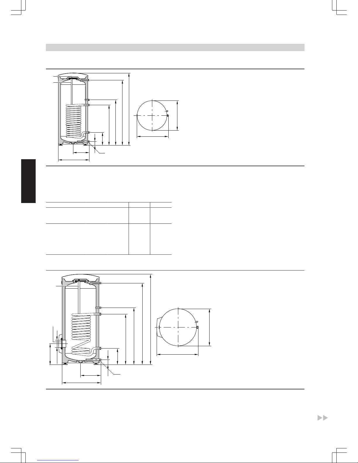
160 and 200 litre capacity
SPR
b
a
c
d
e
f
g
h
k
b
VA
WW
Z
HV/SPR
HR
BÖ
KW/E
BÖ Inspection and cleaning aperture
E Drain
HR Heating water return
HV Heating water flow
KW Cold water
SPR Cylinder temperature sensor of the cylinder temperature control
or the control thermostat
VA Protective magnesium anode
WW DHW
Z DHW circulation
Capacity l 160 200
Length (7) a mm 581 581
Width b mm 608 608
Height c mm 1189 1409
d mm 1050 1270
e mm 884 884
f mm 634 634
g mm 249 249
h mm 72 72
k mm 317 317
300 litre capacity
l
SPR
b
a
c
d
e
f
g
h
k
m
BÖ
VA
WW
Z
HV/SPR
HR
KW/E
b
BÖ Inspection and cleaning aperture
E Drain
HR Heating water return
HV Heating water flow
KW Cold water
SPR Cylinder temperature sensor of the cylinder temperature control
or the control thermostat
VA Protective magnesium anode
WW DHW
Z DHW circulation
DHW cylinder
(cont.)
18
VIESMANN
VITOGAS
3
5822 428 GB
Page 19
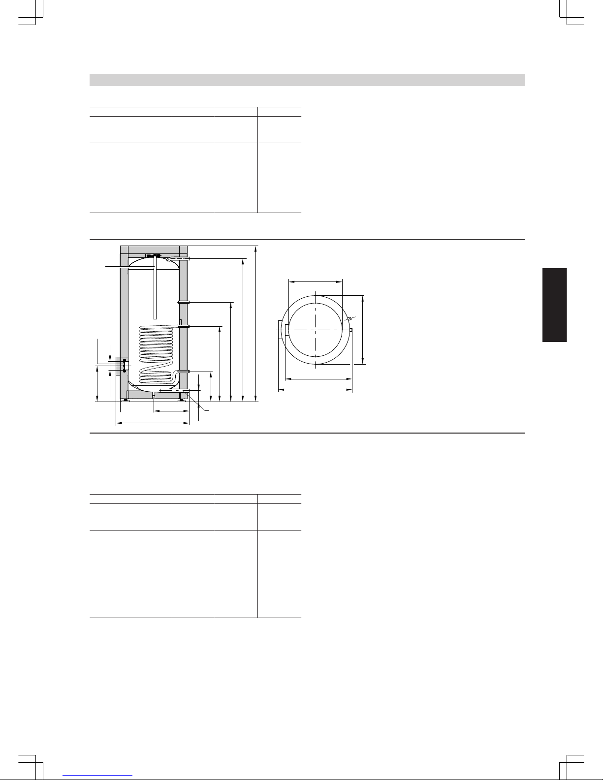
Capacity l 300
Length (7) a mm 633
Width b mm 705
Height c mm 1746
d mm 1600
e mm 1115
f mm 875
g mm 260
h mm 76
k mm 343
l mm 7 100
m mm 333
500 litre capacity
h
a
b
n
o
SPR
l
k
m
BÖ
VA
WW
Z
HR
KW/E
g
f
e
d
c
HV/SPR
b
BÖ Inspection and cleaning aperture
E Drain
HR Heating water return
HV Heating water flow
KW Cold water
SPR Cylinder temperature sensor of the cylinder temperature control
or the control thermostat
VA Protective magnesium anode
WW DHW
Z DHW circulation
Capacity l 500
Length (7) a mm 850
Width b mm 898
Height c mm 1955
d mm 1784
e mm 1230
f mm 924
g mm 349
h mm 107
k mm 455
l mm 7 100
m mm 422
n mm 837
excl. thermal insulation o mm 7 650
DHW cylinder
(cont.)
VITOGAS
VIESMANN
19
5822 428 GB
3
Page 20
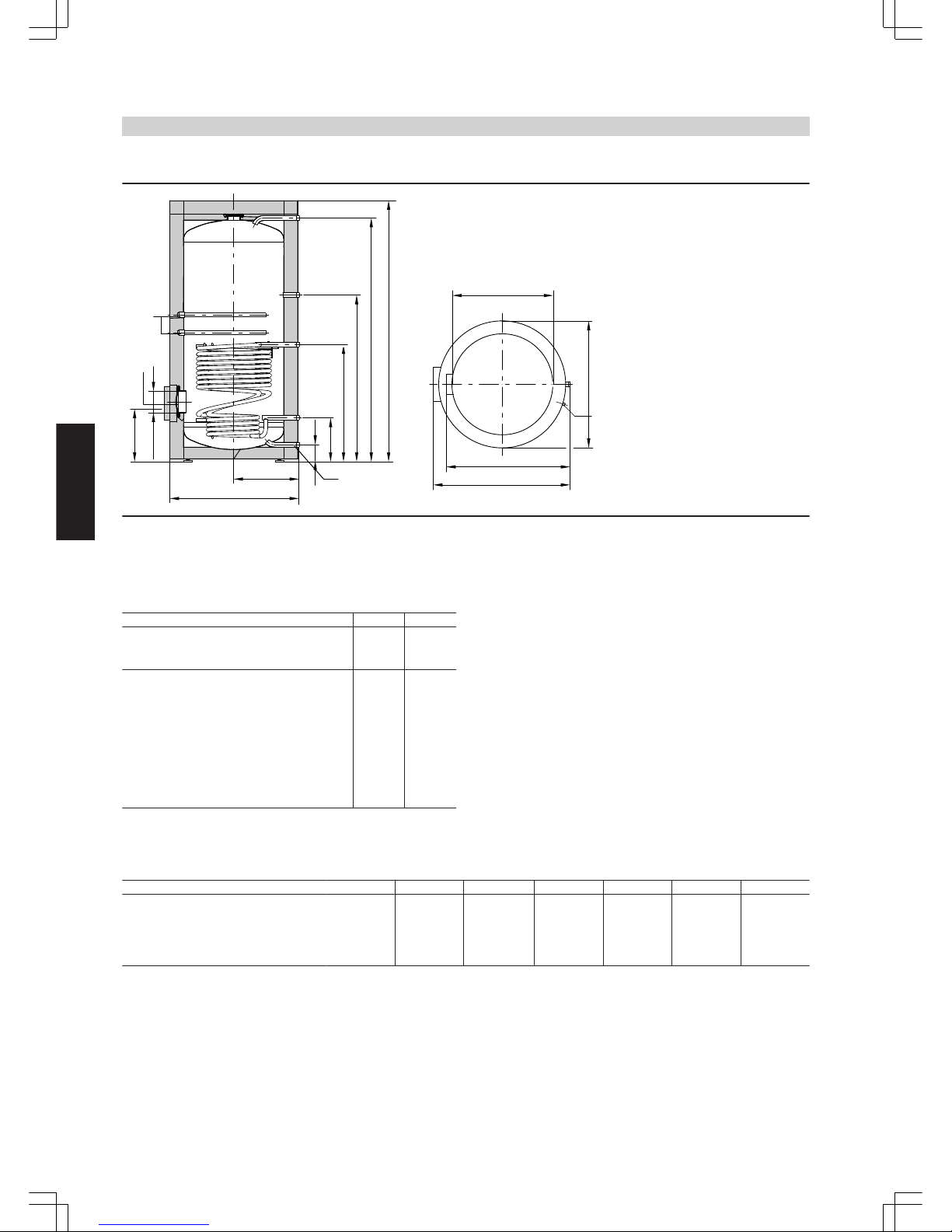
750 and 1000 litre capacity
HR
a
b
n
o
c
d
e
f
g
h
k
l
m
BÖ
WW
Z
SPR
KW/E
VA
HV/SPR
b
BÖ Inspection and cleaning aperture
E Drain
HR Heating water return
HV Heating water flow
KW Cold water
SPR Cylinder temperature sensor of the cylinder temperature control
or the control thermostat
VA Protective magnesium anode
WW DHW
Z DHW circulation
Capacity l 750 1000
Length (7) a mm 960 1060
Width b mm 1046 1144
Height c mm 2100 2160
d mm 1923 2025
e mm 1327 1373
f mm 901 952
g mm 321 332
h mm 104 104
k mm 505 555
l mm 7 180 7 180
m mm 457 468
n mm 947 1047
excl. thermal insulation o mm 7 750 7 850
Performance factor N
L
To DIN 4708.
Cylinder storage temperature T
cyl
= cold water inlet temperature + 50 K
+5 K/-0 K
Capacity l 160 200 300 500 750 1000
Performance factor NL at a heating water flow temperature of
90 °C 2.5 4.0 9.7 21.0 40.0 45.0
80 °C 2.4 3.7 9.3 19.0 34.0 43.0
70 °C 2.2 3.5 8.7 16.5 26.5 40.0
Performance factor N
L
The performance factor NL varies according to the cylinder storage
temperature T
cyl
.
Standard values for
■
T
cyl
= 60 °C → 1.0 × N
L
■
T
cyl
= 55 °C→ 0.75 × N
L
■
T
cyl
= 50 °C → 0.55 × N
L
■
T
cyl
= 45 °C→ 0.3 × N
L
DHW cylinder
(cont.)
20
VIESMANN
VITOGAS
3
5822 428 GB
Page 21

Peak output (during 10 minutes)
Relative to the performance factor NL.
DHW heating from 10 to 45 °C.
Capacity l 160 200 300 500 750 1000
Peak output (l/10 min) at a heating water flow temperature of
90 °C 210 262 407 618 898 962
80 °C 207 252 399 583 814 939
70 °C 199 246 385 540 704 898
Max. draw-off rate (over 10 minutes)
Relative to the performance factor NL.
With booster heating.
DHW heating from 10 to 45 °C.
Capacity l 160 200 300 500 750 1000
Max. draw-off rate (l/min) at a heating water flow temperature of
90 °C 21 26 41 62 90 96
80 °C 21 25 40 58 81 94
70 °C 20 25 39 54 70 90
Available water volume
Cylinder content heated to 60 °C.
Without booster heating.
Capacity l 160 200 300 500 750 1000
Draw-off rate l/min 10 10 15 15 20 20
Available water volume
water at t = 60 °C (continuous)
l 120 145 240 420 615 835
Heat-up time
The heat-up times will be achieved, if the max. continuous output of
the DHW cylinder is made available at the respective heating water
flow temperature and when heating DHW from 10 to 60 °C.
Capacity l 160 200 300 500 750 1000
Heat-up time (min.) at a heating water flow temperature of
90 °C 19 19 23 28 24 36
80 °C 24 24 31 36 33 46
70 °C 34 37 45 50 47 71
DHW cylinder
(cont.)
VITOGAS
VIESMANN
21
5822 428 GB
3
Page 22

Pressure drop
D
E
ACB
Pressure drop in mbar
4
5
6
8
10
20
30
40
50
60
80
100
200
300
400
500
500
600
800
1000
2000
3000
4000
5000
6000
7000
Heating water throughput in litres/h
of one cylinder cell.
Pressure drop on the heating water side
A
Cylinder capacity 160 and 200 l
B
Capacity 300 l
C
Capacity 500 l
D
Capacity 750 l
E
Capacity 1000 l
1
2
3
4
5
6
8
10
20
30
40
50
60
80
100
500
600
800
1000
2000
3000
4000
5000
6000
Pressure drop in mbar
DHW throughput in l/h
C
D
E
A
B
Pressure drop on the DHW side
A
Cylinder capacity 160 and 200 l
B
Capacity 300 l
C
Capacity 500 l
D
Capacity 750 l
E
Capacity 1000 l
Delivered condition
Vitocell 100-V, type CVA
160, 200 and 300 litre capacity
DHW cylinder made from steel with Ceraprotect enamel coating for
DHW heating.
■ Welded-in sensor well for cylinder temperature sensor or thermostat
■ Adjustable feet
■ Protective magnesium anode
■ Fitted thermal insulation made from rigid PU foam
Colour of the epoxy-coated sheet steel casing: Vitosilver.
DHW cylinders with 160, 200 and 300 litre capacity are also available
in white.
Vitocell 100-V, type CVA
500 litre capacity
DHW cylinder made from steel with Ceraprotect enamel coating for
DHW heating.
■ Welded-in sensor well for cylinder temperature sensor or thermostat
■ Adjustable feet
■ Protective magnesium anode
Packed separately:
■ Flexible PUR foam thermal insulation; colour of the plastic-coated
thermal insulation: Vitosilver
Vitocell 100-V, type CVA
750 and 1000 litre capacity
DHW cylinder made from steel with Ceraprotect enamel coating for
DHW heating.
■ Thermometer
■ Welded-in sensor well for cylinder temperature sensor or thermostat
■ Adjustable feet
■ 2 protective magnesium anodes
Packed separately:
■ Flexible PUR foam thermal insulation; colour of the plastic-coated
thermal insulation: Vitosilver
DHW cylinder
(cont.)
22
VIESMANN
VITOGAS
3
5822 428 GB
Page 23

3.2 Specification Vitocell 300-V, type EVA
For DHW heating in conjunction with boilers, peripheral indirect
coils
Suitable for systems with
■ heating water flow temperature up to 110 °C
■ operating pressure on the heating water side up to 3 bar
■ operating pressure on the DHW side up to 10 bar
Cylinder capacity l 130 160 200
DIN reg. no. 0166/04–10MC
Continuous output
for DHW heating from 10 to 45 °C and a heating water flow temperature of ... at the heating
water flow rate stated below
90 °C kW 37 40 62
l/h 909 982 1523
80 °C kW 30 32 49
l/h 737 786 1024
70 °C kW 22 24 38
l/h 540 589 933
60 °C kW 13 15 25
l/h 319 368 614
50 °C kW 9 10 12
l/h 221 245 294
Continuous output
for DHW heating from 10 to 60 °C and a heat-
ing water flow temperature of ... at the heating
water flow rate stated below
90 °C kW 32 36 57
l/h 550 619 980
80 °C kW 25 28 43
l/h 430 481 739
70 °C kW 16 19 25
l/h 275 326 430
Heating water flow rate
m3/h
3.0 3.0 3.0
for the stated continuous outputs
Standby heat loss qBS at 45 K temperature dif-
ferential (actual values to DIN 4753-8)
kWh/24 h 1.30 1.40 1.60
Dimensions
Length (7) a mm 633 633 633
Width b mm 667 667 667
Height c mm 1111 1203 1423
Height when tilted mm 1217 1297 1493
Weight kg 77 84 98
DHW cylinder with thermal insulation
Heating water content l 25 28 35
Heating surface
m
2
1.1 1.3 1.6
Connections
Heating water flow and return R 1" 1" 1"
Cold water, DHW R ¾" ¾" ¾"
DHW circulation R ½" ½" ½"
Information on continuous output
When designing the system for continuous output as stated or calculated, allow for the corresponding circulation pump. The stated continuous output is only achieved when the rated boiler output ≥ continuous output.
DHW cylinder
(cont.)
VITOGAS
VIESMANN
23
5822 428 GB
3
Page 24
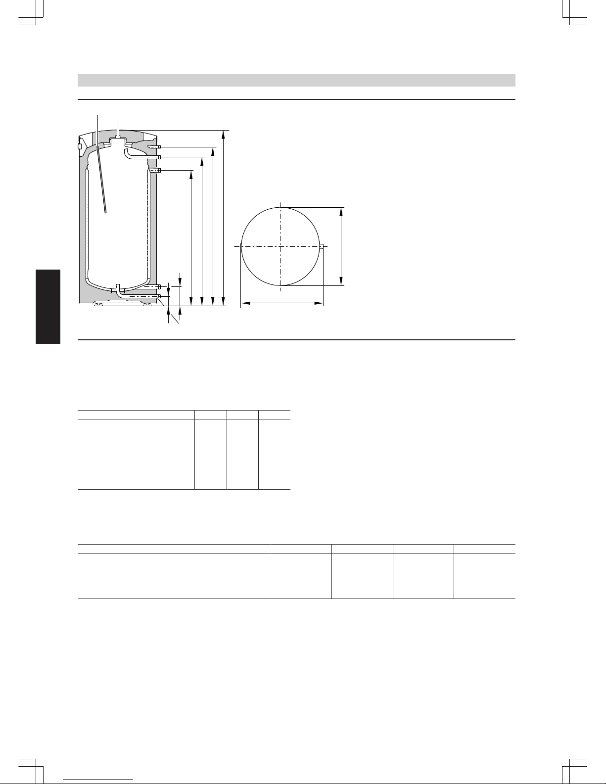
h
g
a
b
BÖ
HR
Z
WW
HV
KW/E
c
d
e
f
SPR
BÖ Inspection and cleaning aperture
E Drain
HR Heating water return
HV Heating water flow
KW Cold water
SPR Sensor well for cylinder temperature sensor or control thermo-
stat
WW DHW
Z DHW circulation
Dimensions
Cylinder capacity l 130 160 200
a mm 633 633 633
b mm 667 667 667
c mm 1111 1203 1423
d mm 975 1067 1287
e mm 892 984 1204
f mm 785 877 1097
g mm 155 155 155
h mm 77 77 77
Performance factor N
L
to DIN 4708
Cylinder storage temperature T
cyl
= cold water inlet temperature +
50 K
+5 K/-0 K
Cylinder capacity l 130 160 200
Performance factor N
L
at heating water flow temperature
90 °C 2.4 3.3 6.8
80 °C 1.9 2.9 5.2
70 °C 1.4 2.0 3.2
Performance factor N
L
The performance factor NL varies according to the cylinder storage
temperature T
cyl
.
Standard values for
■
T
cyl
= 60 °C → 1.0 × N
L
■
T
cyl
= 55 °C → 0.75 × N
L
■
T
cyl
= 50 °C → 0.55 × N
L
■
T
cyl
= 45 °C → 0.3 × N
L
DHW cylinder
(cont.)
24
VIESMANN
VITOGAS
3
5822 428 GB
Page 25

Peak output (over 10 minutes)
Based on performance factor N
L
DHW heating from 10 to 45 °C
Cylinder capacity l 130 160 200
Peak output (l/10 min)
at heating water flow temperature
90 °C 207 240 340
80 °C 186 226 298
70 °C 164 190 236
Max. draw-off rate (over 10 minutes)
Based on performance factor N
L
With booster
DHW heating from 10 to 45 °C
Cylinder capacity l 130 160 200
Max. draw-off rate (l/min)
at heating water flow temperature
90 °C 21 24 34
80 °C 19 23 30
70 °C 16 19 24
Available water volume
Cylinder volume heated to 60 °C
Without booster
Cylinder capacity l 130 160 200
Draw-off rate l/min 10 10 10
Available water volume
Water with t = 60 °C (constant)
l 103 120 150
Heat-up time
The quoted heat-up times will be achieved, if the max. constant output
of the DHW cylinder is made available at the respective flow temperature and when heating the DHW from 10 to 60 °C.
Cylinder capacity l 130 160 200
Heat-up time (min)
at heating water flow temperature
90 °C 15 15 12
80 °C 19 19 26
70 °C 29 29 24
DHW cylinder
(cont.)
VITOGAS
VIESMANN
25
5822 428 GB
3
Page 26

Pressure drop
90
100
10
2000
3000
4000
5000
1000
20
30
40
50
60
70
80
Heating water volume in l/h
of one cylinder cell.
Pressure drop in mbar
Pressure drop on the heating water side
1
0.9
0.8
10
9
8
7
6
5
4
3
2
100
90
80
70
60
50
40
30
20
200
300
400 600 800 1000
2000 4000
120
DHW throughput in l/h
900500 700
3000
Pressure drop in mbar
Pressure drop on the DHW side
Delivered condition
Vitocell 300-V, type EVA, peripheral indirect coil
130 to 200 litre capacity
The DHW side of the DHW cylinder is made from high-alloy stainless
steel with fitted rigid polyurethane foam thermal insulation.
■ Integral welded sensor well for cylinder temperature sensor or control thermostat
■ Integral thermometer
■ Threaded adjustable feet
Colour of the epoxy-coated sheet steel casing: Vitosilver.
DHW cylinders with 160 and 200 litre capacity are also available in
white.
DHW cylinder
(cont.)
26
VIESMANN
VITOGAS
3
5822 428 GB
Page 27
3.3 Specification Vitocell 100-H, type CHA
For DHW heating in conjunction with boilers
Suitable for systems with
■ Heating water flow temperature up to 110 °C
■ DHW temperature up to 95 °C
■ operating pressure on the heating water side up to 10 bar
■ operating pressure on the DHW side up to 10 bar
Cylinder capacity l 130 160 200
DIN register number 0243/06–13 MC/E
Continuous output
for DHW heating from 10 to 45 °C and a
heating water flow temperature of ... at
the heating water throughput stated
below
90 °C
kW 28 33 42
l/h 688 810 1032
80 °C
kW 23 28 32
l/h 565 688 786
70 °C
kW 19 22 26
l/h 466 540 638
60 °C
kW 14 16 18
l/h 344 393 442
Continuous output
for DHW heating from 10 to 60 °C and a
heating water flow temperature of ... at
the heating water throughput stated
below
90 °C
kW 27 32 38
l/h 464 550 653
80 °C
kW 20 24 29
l/h 344 412 498
70 °C
kW 14 17 19
l/h 241 292 326
Heating water throughput
for the stated continuous outputs
m3/h
3.0 3.0 3.0
Standby heat loss qBS at 45 K temperature differential
(actual values to DIN 4753-8)
kWh/24 h 1.20 1.30 1.50
Overall dimensions
Total length d mm 907 1052 1216
Total width e mm 640 640 640
Total height f mm 654 654 654
Weight
DHW cylinder with thermal insulation
kg 90 103 116
Heating water content l 5.5 7 8
Heating surface
m
2
0.8 1 1.2
Connections
Heating water flow and return R 1 1 1
Cold water, hot water R ¾ ¾ ¾
DHW circulation R 1 1 1
Information regarding continuous output
When designing the system for the continuous output as stated or calculated, allow for the corresponding circulation pump. The stated continuous output is only achieved when the rated boiler output ≥ continuous output.
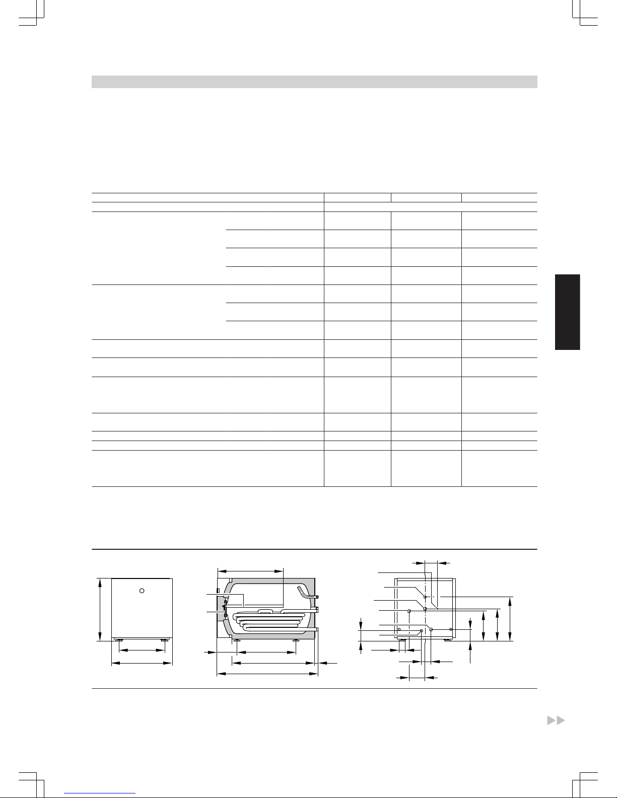
119
Ø 64
203
a
e
f
VA
BÖ
36
d
TH
WW
Z
HV
HR
KW
106
37
167
63
311
336
459
130
479
b
c
BÖ Inspection and cleaning aperture
HR Heating water return
HV Heating water flow
KW Cold water
TH Sensor well for cylinder temperature sensor or control thermo-
stat
VA Protective magnesium anode
DHW cylinder
(cont.)
VITOGAS
VIESMANN
27
5822 428 GB
3
Page 28

WW DHW
Z DHW circulation
Cylinder capacity l 130 160 200
a mm 200 250 300
b mm 471 616 780
c mm 721 866 1030
d mm 907 1052 1216
e mm 640 640 640
f mm 654 654 654
Dim. a: Minimum wall clearance to enable the installation/removal of
the protective magnesium anode.
Performance factor N
L
to DIN 4708
Cylinder storage temperature T
cyl
= cold water inlet temperature +50 K
+5 K/–0 K
Cylinder capacity l 130 160 200
Performance factor N
L
at heating water flow temperature
90 °C 1.3 2.2 3.5
80 °C 1.3 2.2 3.5
70 °C 1.1 1.6 2.5
Performance factor N
L
The performance factor NL varies according to the cylinder storage
temperature T
cyl
.
Standard values
■
T
cyl
= 60 °C → 1.0 × N
L
■
T
cyl
= 55 °C → 0.75 × N
L
■
T
cyl
= 50 °C → 0.55 × N
L
■
T
cyl
= 45 °C → 0.3 × N
L
Peak output (over 10 minutes)
Relative to the performance factor NL and DHW heating from 10 to
45 °C
Cylinder capacity l 130 160 200
Peak output (l/10 min)
at heating water flow temperature
90 °C 159 199 246
80 °C 159 199 246
70 °C 148 173 210
Max. draw-off rate (over 10 minutes)
Based on performance factor N
L
With booster
DHW heating from 10 to 45 °C
Cylinder capacity l 130 160 200
Max. draw-off rate (l/min)
at heating water flow temperature
90 °C 16 20 24
80 °C 16 20 24
70 °C 15 17 21
Available water volume
Cylinder volume heated to 60 °C
Without booster
Cylinder capacity l 130 160 200
Draw-off rate l/min 10 10 10
Available water volume l 100 145 180
Water with t = 60 °C (constant)
DHW cylinder
(cont.)
28
VIESMANN
VITOGAS
3
5822 428 GB
Page 29
Heat-up time
The heat-up times specified will be achieved subject to the maximum
continuous output of the DHW cylinder being made available at the
relevant flow temperature and when DHW is heated from 10 to
60 °C.
Cylinder capacity l 130 160 200
Heat-up time (min)
at heating water flow temperature
90 °C 20 19 18
80 °C 25 26 25
70 °C 34 34 32
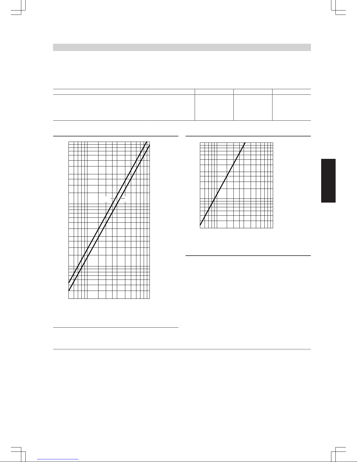
Pressure drop (primary circuit)
3
4
5
6
8
10
20
30
40
50
60
80
100
200
300
400
500
600
800
1000
600
800
1000
2000
3000
4000
5000
6000
8000
10000
Heating water throughput in l/h
Pressure drop in mbar
AB
A
130 litre cylinder capacity
B
160 and 200 litre cylinder capacity
Pressure drop on the DHW side
3
4
5
6
8
10
20
30
40
50
60
80
100
500
600
800
1000
2000
3000
4000
5000
6000
8000
10000
DHW throughput in l/h
Pressure drop in mbar
Delivered condition
Vitocell 100-H, type CHA
130, 160 and 200 litre capacity
DHW cylinder made from steel with Ceraprotect enamel coating.
■ integral protective magnesium anode
■ fitted thermal insulation made from rigid polyurethane foam
■ integral welded sensor well for cylinder temperature sensor or control thermostat and
■ threaded adjustable feet
Colour of the epoxy-coated sheet steel casing: Vitosilver.
DHW cylinder
(cont.)
VITOGAS
VIESMANN
29
5822 428 GB
3
Page 30

3.4 Specification Vitocell 300-H, type EHA
For DHW heating in conjunction with boilers, district heating systems
and low temperature heating systems
Suitable for systems with
■ Heating water flow temperature up to 200 °C
■ operating pressure on the heating water side up to 25 bar or satu-
rated steam with 1 bar positive pressure
■ operating pressure on the DHW side up to 10 bar
Cylinder capacity litres 160 200 350 500
DIN register number 0081/08-10 MC
Continuous output
for DHW heating from 10 to
45 °C and a heating water flow
temperature of ... at the heating
water throughput stated below
90 °C
kW 32 41 80 97
l/h 786 1007 1966 2383
80 °C
kW 28 30 64 76
l/h 688 737 1573 1867
70 °C
kW 20 23 47 55
l/h 490 565 1155 1351
65 °C
kW 17 19 40 46
l/h 417 467 983 1130
60 °C
kW 14 16 33 38
l/h 344 393 811 934
Continuous output
for DHW heating from 10 to
60 °C and a heating water flow
temperature of ... at the heating
water throughput stated below
90 °C
kW 28 33 70 82
l/h 482 568 1204 1410
80 °C
kW 23 25 51 62
l/h 396 430 877 1066
70 °C
kW 15 17 34 39
l/h 258 292 585 671
Heating water throughput
for the stated continuous outputs
m3/h
3.0 5.0 5.0 5.0
Continuous output
for DHW heating from 10 to
45 °C and saturated steam
from ... with a max. steam velocity of 50 m/s
0.5 bar
kW – – 83 83
l/h 2039 2039
1.0 bar
kW – – 105 105
l/h 2580 2580
Standby heat loss qBS at 45 K tempera-
ture differential (actual values to
DIN 4753-8)
kWh/24 h 1.20 1.30 1.90 2.30
Overall dimensions
Total length mm 1072 1236 1590 1654
Total width mm 640 640 830 910
Width without casing mm – – 768 810
Total height mm 654 654 786 886
Weight
DHW cylinder with thermal insulation
kg 76 84 172 191
Heating water content litres 7 8 13 16
Heating surface
m
2
0.87 0.9 1.7 2.1
Connections
Heating water flow and return R 1 1 1¼ 1¼
Cold water, hot water R ¾ ¾ 1¼ 1¼
DHW circulation R 1 1 1 1¼
Information on width without casing (350 and 500 litres)
350 litre: Where access into the boiler room is difficult, the front panel
with thermometer and the side panels can be removed, the
adjustable feet can be unscrewed and the DHW cylinder can
be turned to one side.
500 litre: Where access to the boiler room is difficult, removal of the
casing leaves the DHW cylinder with only the dimensions
given in the table.
Information regarding continuous output
When designing the system for the continuous output as stated or calculated, allow for the corresponding circulation pump. The stated continuous output is only achieved when the rated boiler output ≥ continuous output.
DHW cylinder
(cont.)
30
VIESMANN
VITOGAS
3
5822 428 GB
Page 31
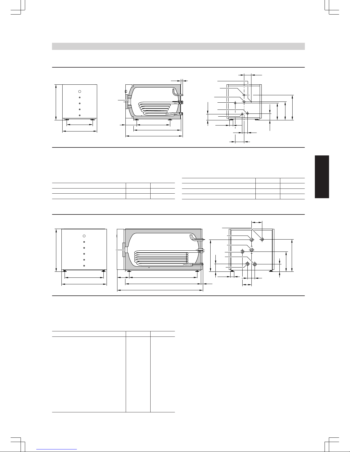
Vitocell 300-H with 160 and 200 litre capacity
Ø 64
336
119
130
37
167
105
d
a
e
36
63
311
459
b
c
479
203
TH
WW
Z
HV
HR
KW
BÖ
BÖ Inspection and cleaning aperture
HR Heating water return
HV Heating water flow
KW Cold water
TH Sensor well for cylinder temperature sensor or control thermo-
stat
WW DHW
Z DHW circulation
Dimensions
Cylinder capacity litres 160 200
a mm 654 654
b mm 640 640
Cylinder capacity litres 160 200
c mm 616 780
d mm 866 1030
e mm 1072 1236
Vitocell 300-H with 350 and 500 litre capacity
Ø 64
221
c
b
35
o
m
n
g
WW
SPR
HV
HR
h
i
k
l
f
e
a
BÖ
p
KW
Z
d
BÖ Inspection and cleaning aperture
HR Heating water return
HV Heating water flow
KW Cold water
SPR Connector R 1" with fem. reducer to R ½" for cylinder tempera-
ture sensor or control thermostat
WW DHW
Z DHW circulation
Dimensions
Cylinder capacity litres 350 500
a mm 786 886
b mm 716 795
c mm 830 910
d mm 1256 1320
e mm 1397 1461
f mm 1590 1654
g mm 586 636
h mm 367 409
i mm 78 78
k mm 57 72
l mm 170 203
m mm 133 137
n mm 139 138
o mm 594 677
p mm 193 226
Note
When installing the sensor well and cylinder temperature sensor,
maintain a minimum distance of 450 mm behind the DHW cylinder.
DHW cylinder
(cont.)
VITOGAS
VIESMANN
31
5822 428 GB
3
Page 32

Performance factor N
L
to DIN 4708
Cylinder storage temperature T
cyl
= cold water inlet temperature +50 K
+5 K/-0 K
Cylinder capacity litres 160 200 350 500
Performance factor N
L
at heating water flow temperature
90 °C 2.3 6.6 12.0 23.5
80 °C 2.2 5.0 12.0 21.5
70 °C 1.8 3.4 10.5 19.0
Performance factor N
L
The performance factor NL varies according to the cylinder storage
temperature T
cyl
.
Standard values
■
T
cyl
= 60 °C → 1.0 × N
L
■
T
cyl
= 55 °C → 0.75 × N
L
■
T
cyl
= 50 °C → 0.55 × N
L
■
T
cyl
= 45 °C → 0.3 × N
L
Peak output (over 10 minutes)
Based on performance factor N
L
DHW heating from 10 to 45 °C
Cylinder capacity litres 160 200 350 500
Peak output (litres/10 minutes)
at heating water flow temperature
90 °C 203 335 455 660
80 °C 199 290 445 627
70 °C 182 240 424 583
Max. draw-off rate (over 10 minutes)
Based on performance factor N
L
With booster
DHW heating from 10 to 45 °C
Cylinder capacity litres 160 200 350 500
Max. draw-off rate (litres/minute)
at heating water flow temperature
90 °C 20 33 45 66
80 °C 20 29 45 62
70 °C 18 24 42 58
Available water volume
Cylinder volume heated to 60 °C
Without booster
Cylinder capacity litres 160 200 350 500
Draw-off rate l/min 10 10 15 15
Available water volume
Water with t = 60 °C (constant)
litres 150 185 315 440
Heat-up time
The heat-up times specified will be achieved subject to the maximum
continuous output of the DHW cylinder being made available at the
relevant flow temperature and when DHW is heated from 10 to
60 °C.
Cylinder capacity litres 160 200 350 500
Heat-up time (minutes)
at heating water flow temperature
90 °C 19 18 15 20
80 °C 26 25 20 26
70 °C 34 32 31 40
DHW cylinder
(cont.)
32
VIESMANN
VITOGAS
3
5822 428 GB
Page 33

Pressure drop (primary circuit)
A
D
4
3
5
6
8
10
20
30
40
50
60
80
100
200
300
400
500
600
800
1000
500
600
800
1000
2000
3000
4000
5000
6000
8000
10 000
Pressure drop in mbar
Heating water throughput in litres/h
of one cylinder cell.
C
B
A
160 litre cylinder capacity
B
200 litre cylinder capacity
C
350 litre cylinder capacity
D
500 litre cylinder capacity
Pressure drop on the DHW side
A
B
1
10
9
8
7
6
5
4
3
2
20
500
700 900
1000
2000
3000
4000
5000600 800
DHW throughput in l/h
of one cylinder cell.
Pressure drop in mbar
A
160 and 200 litre cylinder capacity
B
350 and 500 litre cylinder capacity
Delivered condition
Vitocell 300-H, type EHA, 160 and 200 litre capacity Vitocell 300-H, type EHA, 350 and 500 litre capacity
DHW cylinders made from high-alloy stainless steel.
– fitted thermal insulation made from rigid polyurethane foam
– integral welded sensor well for cylinder temperature sensor or control
thermostat
– integral thermometer and
– threaded adjustable feet
Colour of the epoxy-coated sheet steel casing: Vitosilver.
DHW cylinders made from high-alloy stainless steel.
– with fitted thermal insulation made from rigid polyurethane foam
– Connectors for cylinder temperature sensor or control thermostat
– integral thermometer and
– threaded adjustable feet.
Packed separately and fitted to the crate:
– Female reducer R 1 × ½"
– sensor well and
– thermal insulation piece for the sensor well
Colour of the epoxy-coated sheet steel casing: Vitosilver.
DHW cylinder
(cont.)
VITOGAS
VIESMANN
33
5822 428 GB
3
Page 34
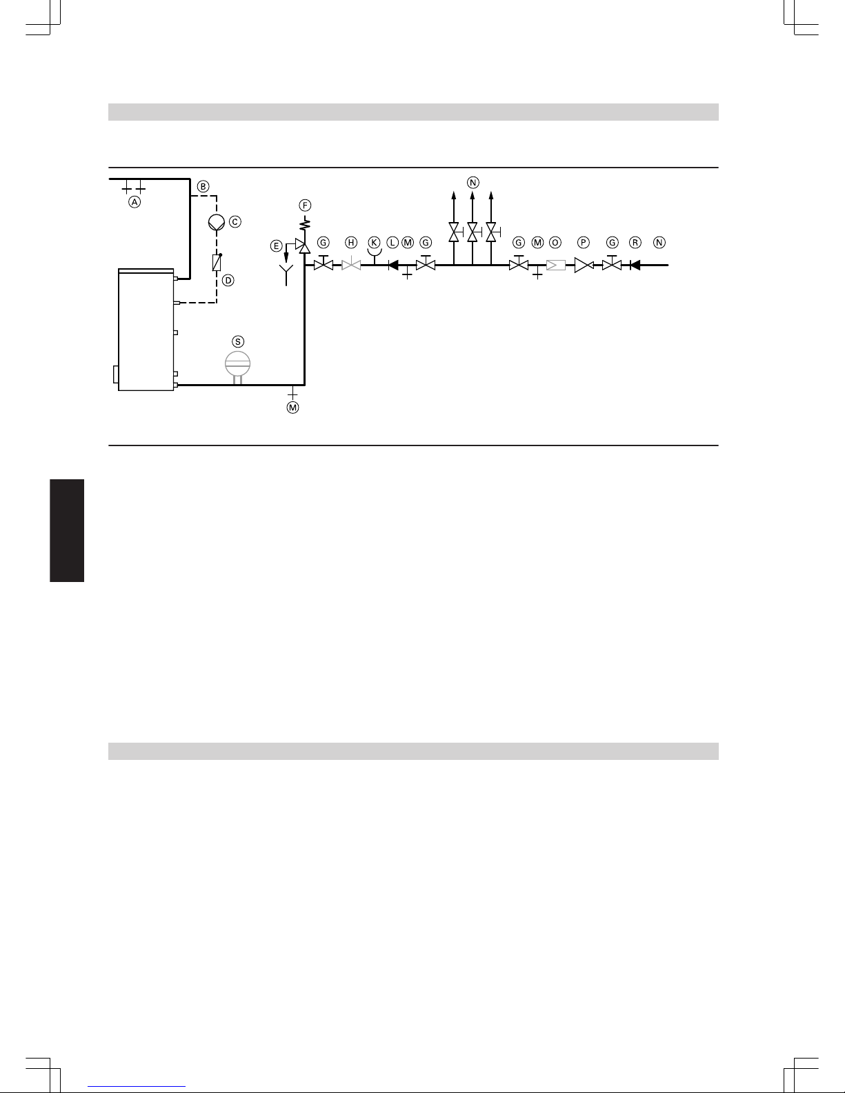
3.5 DHW cylinder connection on the DHW side
Connection to DIN 1988, example: Vitocell 100-V
A
DHW
B
DHW circulation line
C
DHW circulation pump
D
Spring-loaded check valve
E
Blow-off line with a visible outlet
F
Safety valve
G
Shut-off valve
H
Flow regulating valve
(Recommendation: we recommend installing this valve and
adjusting the max. water flow rate in accordance with the 10
minute peak output of the DHW cylinder.)
K
Pressure gauge connector
L
Non-return valve
M
Drain
N
Cold water
O
Drinking water filter
P
Pressure reducer to DIN 1988-2, issue Dec, 1988
R
Non-return valve/pipe separator
S
Diaphragm expansion vessel, suitable for drinking water
Information on drinking water filter
According to DIN 1988-2, a drinking water filter should be installed in
systems with metal pipework. Viessmann and DIN 1988 also recommend the installation of a drinking water filter when using plastic pipes,
to prevent contamination entering the DHW system.
The safety valve must be installed. Recommendation: Install the safety valve higher than the top edge of
the cylinder. This protects the valve against contamination, scaling and
high temperatures. The DHW cylinder must not be drained when working on the safety valve.
Installation accessories
4.1 Accessories for connecting DHW cylinder to boiler
System connections with Vitocell
Complete with:
■ Connecting pipes
■ Circulation pump, fully wired
■ Check valve
For part numbers for the relevant cylinder types, see pricelist.
DHW cylinder
(cont.)
34
VIESMANN
VITOGAS
4
5822 428 GB
Page 35

Safety assembly to DIN 1988
Safety assembly, comprising:
■ Shut-off valve
■ Non-return valve and test connector
■ Pressure gauge connector
■ Diaphragm safety valve
For DHW cylinder:
■ Up to 200 litre capacity: DN 15/R ¾
Maximum heat input 75 kW
10 bar: Part no. 7219 722
■ From 300 to 1000 litre capacity: DN 20/R 1
Maximum heat input 150 kW
10 bar: Part no. 7180 662
4.2 Accessories for heating circuits
Divicon heating circuit distributor
Construction and function
■ Available with R ¾ , R 1 and R 1¼ connections.
■ With heating circuit pump, check valve, ball valves with integral thermometers and 3-way mixer or without mixer.
■ Quick and simple installation through pre-assembled unit and compact design.
■ Low radiation losses through all-round thermal insulation shells.
■ Low electricity costs and precise control characteristics through the
use of high efficiency pumps and optimised mixer curve.
■ Also available with staged pumps.
■ The bypass valve for hydraulic balancing of the heating system is
available as an accessory as a threaded component for inserting into
the prepared hole in the cast body.
■ The overflow valve may be required when using staged pumps to
prevent the heating system running noisily. It is mounted onto the
Divicon.
■ For direct connection on the boiler by means of a pipe assembly
(single installation) or for wall mounting as single as well as double
or triple manifold.
■ Also available as kit. For further details, see the Viessmann pricelist.
Installation accessories
(cont.)
VITOGAS
VIESMANN
35
5822 428 GB
4
Page 36
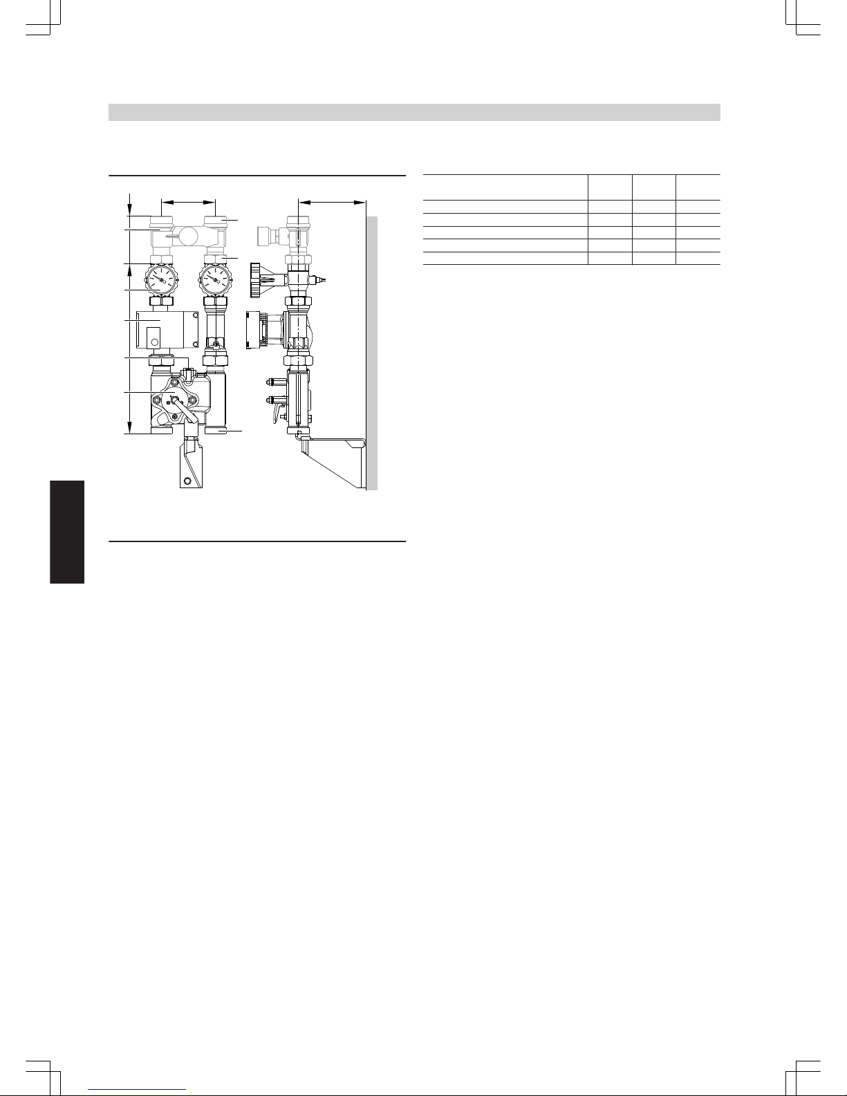
For part no. in conjunction with the different circulation pumps, see Viessmann pricelist.
The dimensions of the heating circuit distributor are the same, with or without mixer.
E
151
398
A
B
C
D
G 1½
98
120
HV HR
a
b
HV HRHV HR
Divicon with mixer (wall mounting without thermal insulation and without mixer drive extension set)
HR Heating return
HV Heating flow
A
Overflow valve (accessory for multi-stage circulation pump)
B
Ball valves with thermometer (as programming unit)
C
Circulation pump
D
Bypass valve (accessory)
E
Three-way mixer
Heating circuit connection
R ¾ 1 1¼
Flow rate (max.)
m3/h
1.0 1.5 2.5
a (female) Rp ¾ 1 1¼
a (male) G 1¼ 1½ 2
b (female) Rp ¼ 1 1¼
b (male) G 1¼ 1¼ 2
Installation accessories
(cont.)
36
VIESMANN
VITOGAS
4
5822 428 GB
Page 37
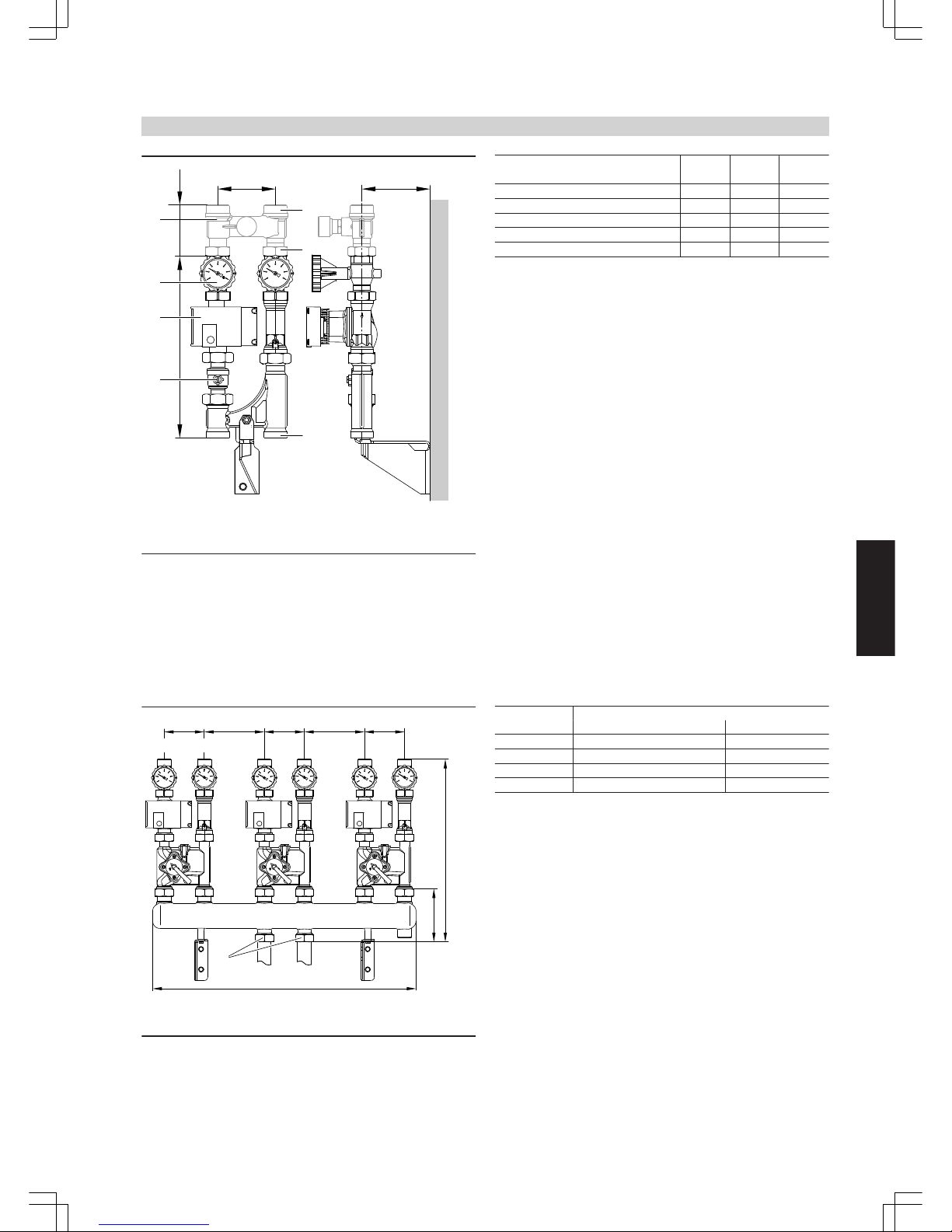
142
398
A
B
C
HV HR
98
120
D
G 1½
a
b
HV HR
Divicon without mixer (wall mounting, shown without thermal insulation)
HR Heating return
HV Heating flow
A
Overflow valve (accessory for multi-stage circulation pump)
B
Ball valves with thermometer (as programming unit)
C
Circulation pump
D
Ball valve
Heating circuit connection
R ¾ 1 1¼
Flow rate (max.)
m3/h
1.0 1.5 2.5
a (female) Rp ¾ 1 1¼
a (male) G 1¼ 1½ 2
b (female) Rp ¼ 1 1¼
b (male) G 1¼ 1¼ 2
Installation example: Divicon with triple manifold
HV HR
120 120 120
b
a
d
c
180 180
HV HR
(shown without thermal insulation)
HR Heating return
HV Heating flow
Dimensions Manifold with heating circuit connection
R ¾ and R 1 R 1¼
a 135 183
b 535 583
c 784 784
d G 1¼ G 2
Installation accessories
(cont.)
VITOGAS
VIESMANN
37
5822 428 GB
4
Page 38

Determining the required internal diameter
A
ΔT= 15K
ΔT= 20K
ΔT= 30K
ΔT= 5K
ΔT= 10K
C
B
D
2.5
2.5
Mixer control characteristics
2.0
0.1
0.2
0.5
1.0
1.5
5.0
Flow rate in m³/h
10 20 30 40531
0.1
0.2
0.5
1.0
1.5
2.0
5.0
Heating circuit output
in kW
A
Divicon with three-way mixer
The identified operating ranges B to D provide optimum control
characteristics with the Divicon mixer:
B
Divicon with three-way mixer (R ¾)
Application range: 0 to 1.0 m 3/h
C
Divicon with three-way mixer (R 1)
Application range: 0 to 1.5 m 3/h
D
Divicon with three-way mixer (R 1¼)
Application range: 0 to 2.5 m 3/h
Example:
Heating circuit for radiators with an output of ² = 11.6 kW
Heating system temperature 75/60 °C (ΔT = 15 K)
c Specific heat capacity
µ
Mass flow rate
²
Output
´
Flow rate
² = µ · c · ΔT c = 1.163
Wh
kg · K
µ
²
c · ΔT
=
kg
h
´ =
11600 W · kg · K
1.163 Wh · (75-60) K
= 665
m³
h
0.665
´ (1 kg ≈ 1 dm³)
Select the smallest possible mixer within the application range with
value ´.
Result of this example: Divicon with three-way mixer (R ¾)
Circulation pump curves and pressure drop on the heating water side
The residual pump head results from the difference between the selected pump curve and the pressure drop curve of the respective heating
circuit distributor or further components (pipe assembly, distributor
etc.).
The following pump diagrams show the pressure drop curves of the
different Dicivon heating circuit distributors.
Maximum flow rate for Divicon:
■
with R ¾ = 1.0 m3/h
■
with R 1 = 1.5 m3/h
■
with R 1¼ = 2.5 m3/h
Example:
Flow rate ´ = 0.665 m3/h
Selected:
Divicon with mixer R ¾ and circulation pump Wilo VIRS 25/4-3, pump
curve 2, pump rate 0.7 m 3/h
Head of the relevant pump
curve: 28 kPa
Divicon pressure drop: 3.5 kPa
Residual head: 28 kPa – 3.5 kPa = 24.5 kPa.
Note
For further components (pipe assembly, distributor, etc.) determine the
pressure drop and deduct it from the residual head.
Installation accessories
(cont.)
38
VIESMANN
VITOGAS
4
5822 428 GB
Page 39

Manually controlled heating circuit pumps
Wilo VIRS 25/4-3
min.1
Max. head 3
40
0
10
20
30
0
100
200
300
400
0 0.5 1.0 1.5 2.0 2.5
Pump rate in m³/h
Pressure drop/head
mbar
kPa
50500
2
A
B
C
D
A
Divicon R ¾ with mixer
B
Divicon R 1 with mixer
C
Divicon R 1¼ with mixer
D
Divicon R ¾, R 1 and R 1¼ without mixer
Wilo VIRS 25/6-3
Head min.1
Head max.3
40
0
10
20
30
0
100
200
300
400
0 0.5 1.0 1.5 2.0 2.5
Pump rate in m³/h
Pressure drop/head
mbar
kPa
50
500
60
600
2
A
B
C
D
A
Divicon R ¾ with mixer
B
Divicon R 1 with mixer
C
Divicon R 1¼ with mixer
D
Divicon R ¾, R 1 and R 1¼ without mixer
Grundfos VIUPS 25-40
Head min.
Head max.
A
B
C
D
0
10
20
30
0
100
200
300
40400
0 0.5 1.0 1.5 2.0 2.5
Pump rate in m³/h
Pressure drop/head
mbar
kPa
A
Divicon R ¾ with mixer
B
Divicon R 1 with mixer
C
Divicon R 1¼ with mixer
D
Divicon R ¾, R 1 and R 1¼ without mixer
Grundfos VIUPS 25-60
Max. head
Min. head
60600
40
0
10
20
30
0
100
200
300
400
0 0.5 1.0 1.5 2.0 2.5
Pump rate in m³/h
Pressure drop/head
mbar
kPa
50500
A
B
C
D
A
Divicon R ¾ with mixer
B
Divicon R 1 with mixer
C
Divicon R 1¼ with mixer
D
Divicon R ¾, R 1 and R 1¼ without mixer
Installation accessories
(cont.)
VITOGAS
VIESMANN
39
5822 428 GB
4
Page 40
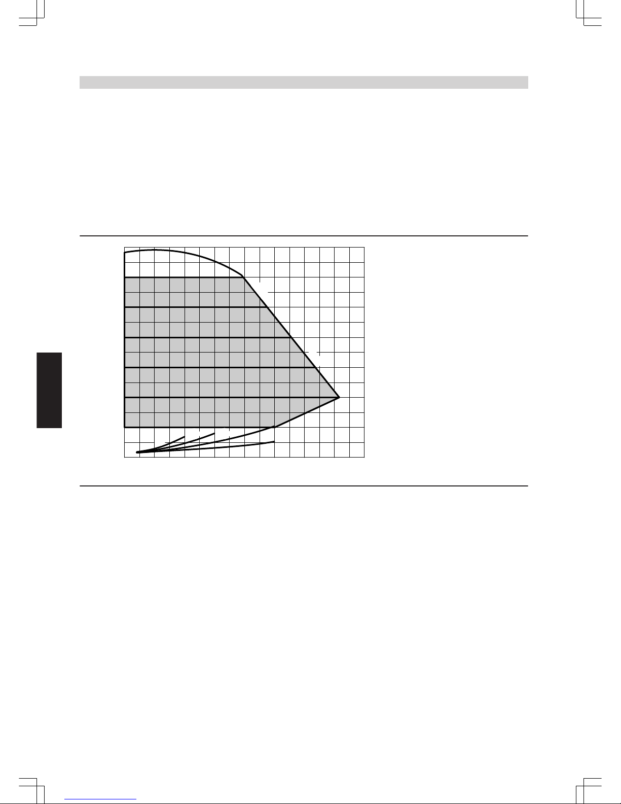
Heating circuit pumps regulated by differential pressure
According to the [German] Energy Savings Order (EnEV), circulation
pumps in central heating systems must be sized in accordance with
current technical rules. Circulation pumps in central heating systems
with rated output higher than 25 kW should be equipped and designed
in such a way that the power consumption will be automatically
matched to the operational (capacity) requirements in at least 3 stages,
if no safety concerns relating to the boiler make demands to the contrary.
In addition to the EnEV regulations, the use of regulated pumps is also
recommended for smaller capacities.
Design information
The use of differential pressure regulated heating circuit pumps
requires heating circuits with variable flow rate, e.g. single line and
twin-line systems with thermostatic valves, underfloor heating with
thermostatic or zone valves.
Wilo Stratos Para 25/1-7
■ Very economical HE pump (in accordance with Energy Label A)
Operating mode: Constant differential pressure
D
A
40
0
10
20
30
0
100
200
300
400
0 0.5 1.0 1.5 2.0 2.5
Pump rate in m³/h
Pressure drop/head
mbar
kPa
50500
60600
3.0 3.5 4.0
70700
B
C
Δp-C
max.
A
Divicon R ¾ with mixer
B
Divicon R 1 with mixer
C
Divicon R 1¼ with mixer
D
Divicon R ¾, R 1 and R 1¼ without mixer
Installation accessories
(cont.)
40
VIESMANN
VITOGAS
4
5822 428 GB
Page 41
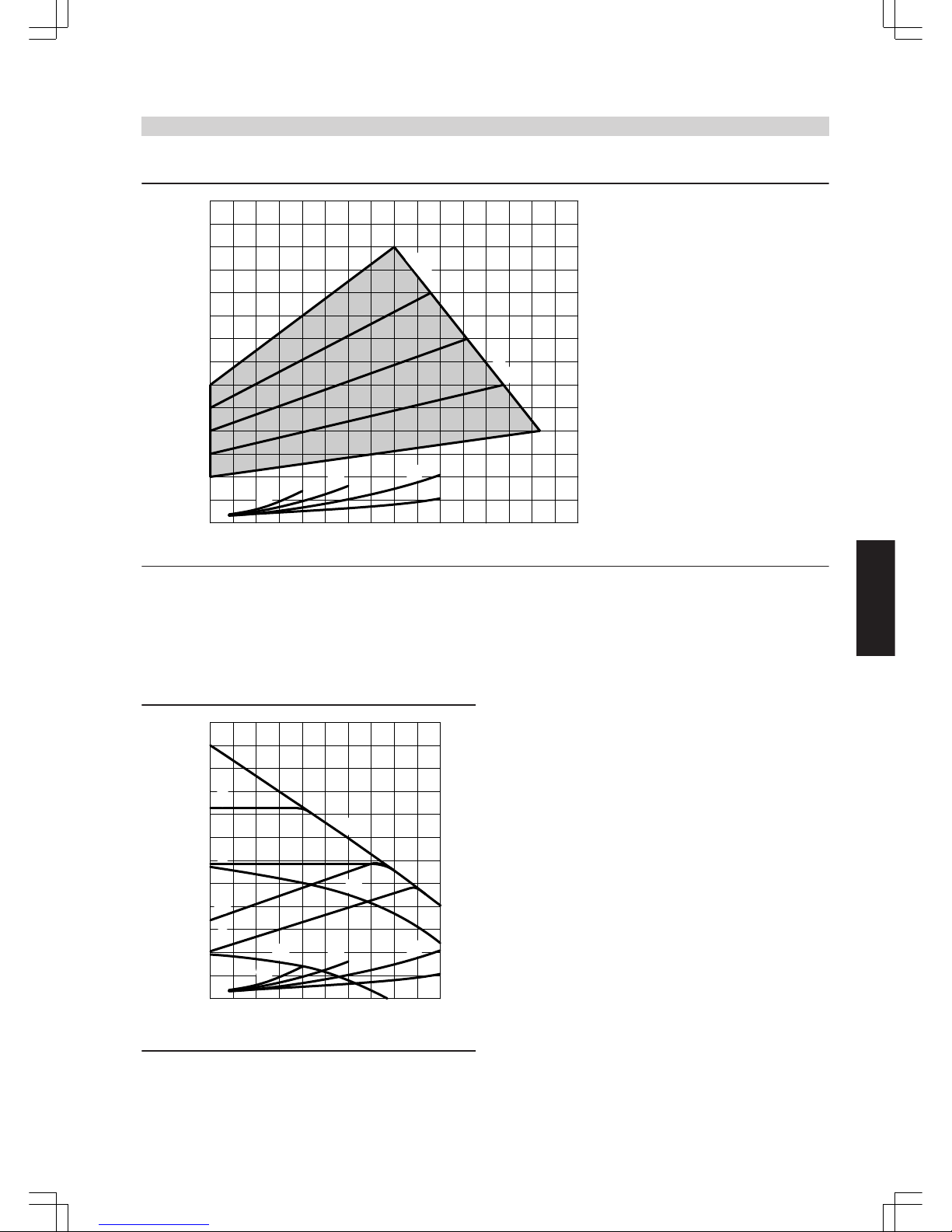
Operating mode: Variable differential pressure
D
A
40
0
10
20
30
0
100
200
300
400
0 0.5 1.0 1.5 2.0 2.5
Pump rate in m³/h
Pressure drop/head
mbar
kPa
50500
60600
3.0 3.5 4.0
70700
Δp-V
max.
B
C
A
Divicon R ¾ with mixer
B
Divicon R 1 with mixer
C
Divicon R 1¼ with mixer
D
Divicon R ¾, R 1 and R 1¼ without mixer
Grundfos Alpha 2-60
■ Very economical HE pump (in accordance with Energy Label A)
■ with power consumption indication
■ with Autoadapt function (automatic matching to the pipework)
■ with night setback function
D
A
B
C
E
F
G
H
K
L
M
40
0
10
20
30
0
100
200
300
400
0 0.5 1.0 1.5 2.0 2.5
Pump rate in m³/h
Pressure drop/head
mbar
kPa
50500
60600
A
Divicon R ¾ with mixer
B
Divicon R 1 with mixer
C
Divicon R 1¼ with mixer
D
Divicon R ¾, R 1 and R 1¼ without mixer
E
Stage 1
F
Stage 2
G
Stage 3
H
Min. proportional pressure
K
Max. proportional pressure
L
Min. constant pressure
M
Max. constant pressure
Bypass valve
Part no. 7464 889
To hydraulically balance the heating circuit with mixer. Inserted into
the Divicon.
Overflow valve
Part no. 7429 738: R ¾
Part no. 7429 739: R 1
Part no. 7429 740: R 1¼
Only with manually controlled heating circuit pumps. Fitted onto the
Divicon.
Installation accessories
(cont.)
VITOGAS
VIESMANN
41
5822 428 GB
4
Page 42
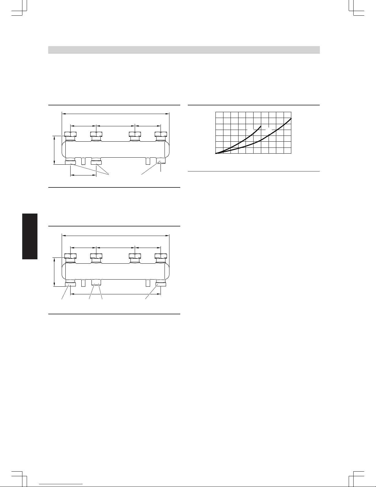
Manifold
incl. thermal insulation
Wall mounted with wall mounting bracket to be ordered separately.
The connection between boiler and manifold must be made on site.
For 2 Divicon
Part no. 7460 638 for Divicon R ¾ and R 1
HV HR HV HR
120
495
HV HR
120
135
120
A
180
G 1½ Rp ¾
A
Connection option for expansion vessel
HV Heating water flow
HR Heating water return
Part no. 7466 337 for Divicon R 1¼
HV HR HV HR
120
495
HV HR
420
183
120
A
180
G 2
Rp ¾
G 2
A
Connection option for expansion vessel
HV Heating water flow
HR Heating water return
Pressure drop
0
0 0.5 1 1.5 2
Flow rate in m³/h
0.5
1
1.5
2
3
2.5
3.5
2.5
Pressure
drop
kPa
A B
A
Manifold for Divicon R ¾ and R 1
B
Manifold for Divicon R 1¼
Installation accessories
(cont.)
42
VIESMANN
VITOGAS
4
5822 428 GB
Page 43
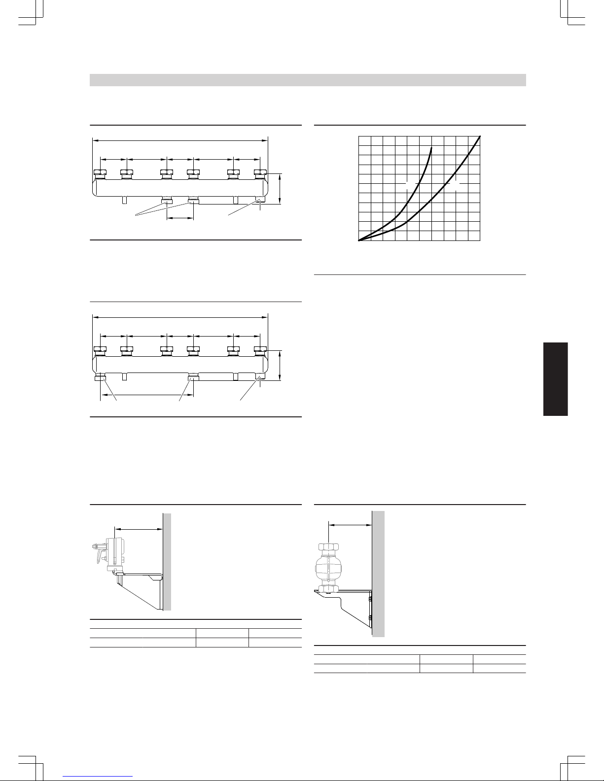
For 3 Divicon
Part no. 7460 643 for Divicon R ¾ and R 1
120
HV HR HV HR HV HR
120 120
784
HV HR
135
A
180 180
120
G 1½
Rp ¾
A
Connection option for expansion vessel
HV Heating water flow
HR Heating water return
Part no. 7466 340 for Divicon R 1¼
120
HV HR HV HR HV HR
120 120
784
HV HR
183
A
180 180
420
G 2
Rp ¾
G 2
A
Connection option for expansion vessel
HV Heating water flow
HR Heating water return
Pressure drop
0
0 0.5 1 1.5 2
Flow rate in m³/h
0.5
1
1.5
2
3
2.5
3.5
2.5
Pressure
drop
kPa
4
4.554.5
5.5
A B
A
Manifold for Divicon R ¾ and R 1
B
Manifold for Divicon R 1¼
Wall mounting bracket
Part no. 7465 894
for individual Divicon
With screws and dowels.
a
for Divicon with mixer without mixer
a mm 151 142
Part no. 7465 439
for manifold
With screws and dowels.
a
for Divicon R ¾ and R 1 R 1¼
a mm 142 167
Installation accessories
(cont.)
VITOGAS
VIESMANN
43
5822 428 GB
4
Page 44
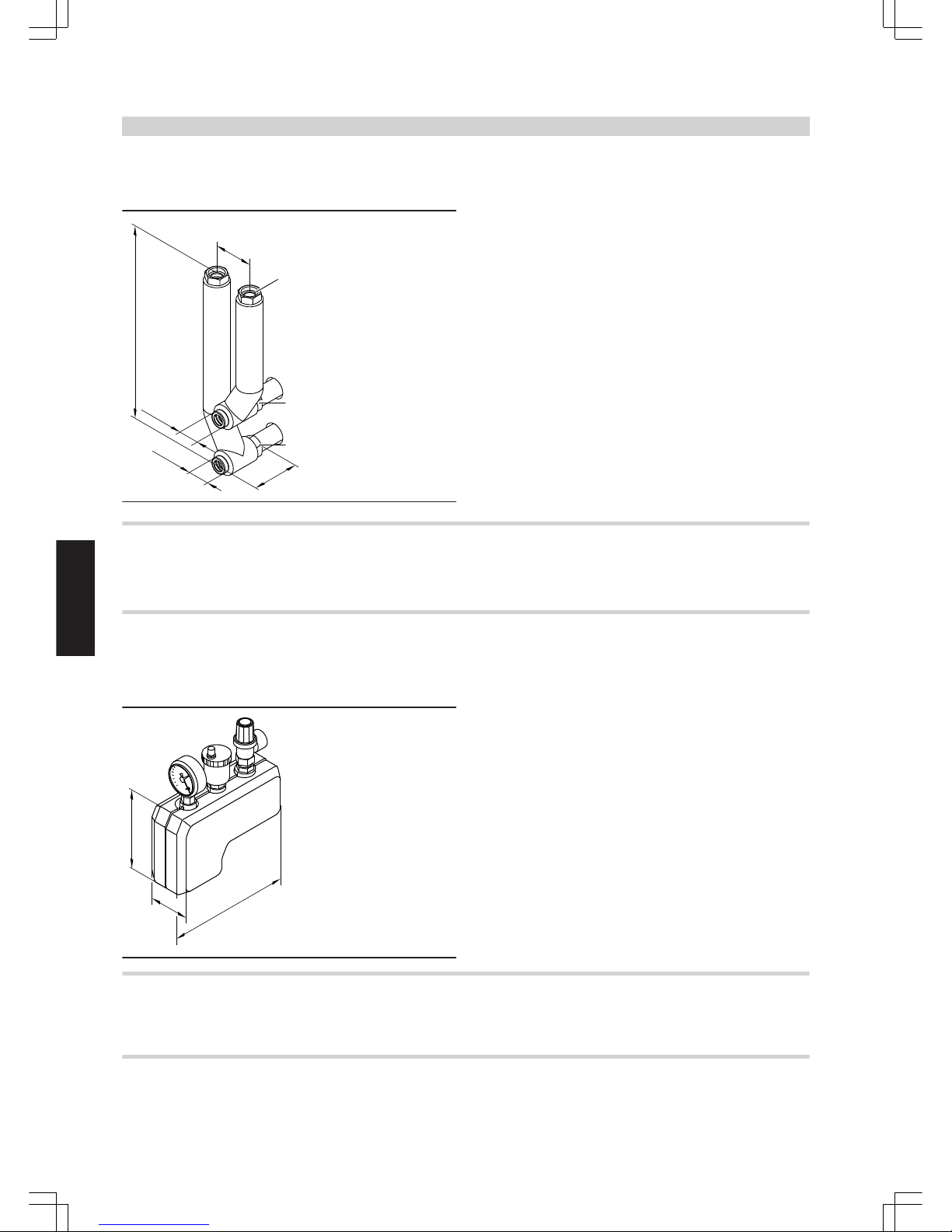
Pipe assembly
Part no. 7439 211
For fitting a Divicon to the boiler flow and return connector.
120
G 1½
575
HV
HR
120
G 1½
G 1½
4.3 Boiler accessories
Four-way mixer
For for-way mixer and matching mixer motors, see Viessmann pricelist.
Safety equipment block
■ with safety assembly
■ incl. thermal insulation
Part no. 7143 779 for 15 to 40 kW
Part no. 7143 780 for 50 and 63 kW
232
80
144
■ with safety valve R ½ or R ¾ (blow-off pressure 3 bar)
■ with pressure gauge
■ with automatic air vent valve with automatic shut-off facility
■ incl. thermal insulation
Plinth for Vitogas 200-F
Height: 250 mm ■ Part no. 7196 461 for 11 to 22 kW
■ Part no. 7196 462 for 29 to 35 kW
■ Part no. 7196 463 for 42 to 60 kW
Plinth for Vitogas 100-F
Height: 250 mm ■ Part no. 7187 612 for 29 to 35 kW
■ Part no. 7187 613 for 42 to 60 kW
Installation accessories
(cont.)
44
VIESMANN
VITOGAS
4
5822 428 GB
Page 45

Flue gas monitoring sensor
Part no. 7266 023
Sensor for installation in draught hood with plug "CN2" for burner control unit.
If flue gas enters the installation room, the flue gas monitoring device
switches the burner off.
Design information
5.1 Selection of rated output
Select a boiler according to the required heat demand including DHW
heating.
The rated output for low temperature boilers, condensing boilers and
multi-boiler systems may be higher than the calculated heat demand
of the building in question.
The level of efficiency of low temperature boilers is consistent across
a wide boiler load range.
5.2 System design
The boiler water temperature is limited to 75 °C.
The boiler water temperature and the flow temperature can be raised
by adjusting the thermostat.
To minimise distribution losses, we recommend that you size the heat
distribution system and the DHW heating system for a max. flow temperature of 70 °C.
5.3 Flue system
With draught in the flue gas system exceeding 10 Pa, we recommend
the installation of a Vitoair combined draught stabiliser (for chimney
installation) near the ceiling (see the separate datasheet in register 9).
5.4 Safety equipment
Equip these boilers with a type-tested safety valve in accordance with
EN 12828 for hot water heating systems with a safety temperature of
up to 110 °C.
This must be identified in accordance with TRD 721 as follows:
■ "H" up to 3.0 bar permissible operating pressure and max.
2700 kW rated output
■ "D/G/H" for all other operating conditions.
5.5 Thermal safety shut-off valve
According to paragraph 4, section 5 of the FeuVo '96 [or local regulations], thermally activated shut-off equipment must be installed in combustion equipment or in gas lines immediately upstream of the combustion equipment, which will shut off the gas supply, if the external
temperature exceeds 100 °C.
These valves must isolate the gas supply for at least 30 minutes up to
a temperature of 650 °C. This should prevent the formation of explosive gas mixtures in the event of a fire.
5.6 Heating circuits
For heating systems with plastic pipes, we recommend the use of
impermeable pipes to prevent the diffusion of oxygen through the pipe
walls. Provide system separation in heating systems with plastic pipes
to DIN 4726 that are permeable to oxygen. We supply a separate heat
exchanger for this.
We recommend a return temperature raising facility for systems with
a water content > 15 l/kW.
Underfloor heating systems and heating circuits with very large water
content should be connected to the boiler via a three-way mixer; see
the technical guide on "Control of underfloor heating systems".
Install a temperature limiter into the flow of the underfloor heating circuit to limit the maximum temperature.
Observe the requirements of DIN 18560-2 [or local regulations].
5.7 Plastic pipework for radiators
We also recommend the installation of a temperature limiter to limit the
maximum temperature of plastic pipes in heating circuits with radiators.
Installation accessories
(cont.)
VITOGAS
VIESMANN
45
5822 428 GB
5
Page 46
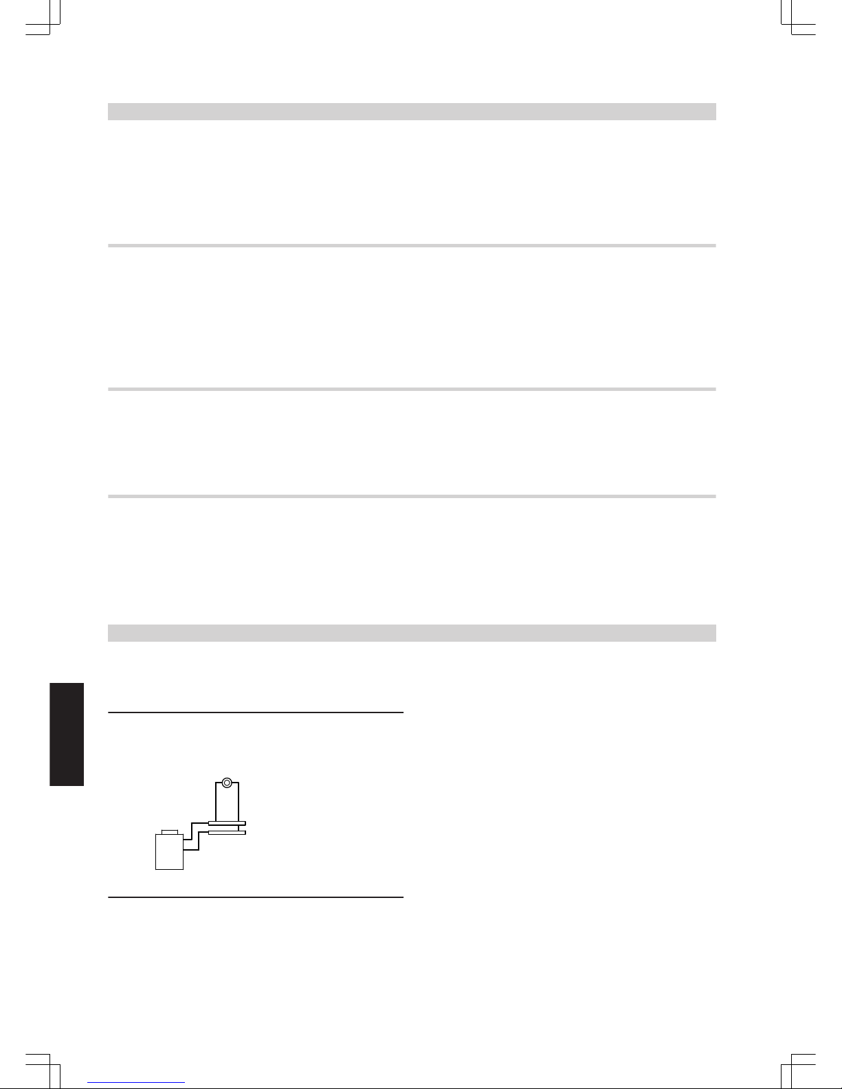
5.8 Additional requirements when installing boilers for LPG operation in rooms below
ground level
According to TRF 1996 Vol. 2 – valid as of 1 September 1997 – an
external safety solenoid valve is no longer required when installing the
boiler below ground level.
However, the high safety standard derived from the use of an external
safety solenoid valve has proved to be valuable. We therefore recommend the continued installation of an external safety solenoid valve
when installing the boiler below ground level.
5.9 Flue gas monitoring device
The EC Gas Appliances Directive specifies the installation of a flue gas
monitoring device for gas boilers up to 50 kW, if the installation room
is not sealed against other rooms of the accommodation or utility area
and is not provided with adequate ventilation.
This does not apply if the installation room is separated from other
rooms through thick walls and tightly fitting, self-closing doors or if it is
adequately ventilated according to the "ventilation requirements"
specified by the TRGI [Germany or by local ventilation regulations].
The flue gas monitoring device can also, e.g. on request of the building
owner, be retrofitted in non-living spaces after the installation of the
boiler.
5.10 Low water indicator
According to the EN 12828, special low water level protection can be
omitted for boilers up to 300 kW, as long as heating can be reliably
prevented when the water level is too low.
Viessmann Vitogas are equipped with type-tested thermostats and
high limit safety cut-outs. Tests have verified that the burner will be
automatically switched OFF in the event of water shortage due to a
leak in the heating system and simultaneous burner operation, before
the boiler or the flue system reach unacceptably high temperatures.
5.11 System water quality
For boilers with a rated output in excess of 50 kW, soften the water in
accordance with VDI 2035-1 under the following circumstances:
■ If the total amount of alkaline earths is in excess of 2.0 mol/m³.
■ If the volume of fill and top-up water exceeds three times the water
content of the heat system during its service life.
■ If the specific system volume is in excess of 20 l/kW.
For further details regarding the water quality requirements, see the
technical guide Vitogas from 72 kW.
Control units
6.1 Overview of control unit types
Vitotronic 100, type KC3
Electro-mechanical boiler control unit:
■ For one heating circuit without mixer
■ For a single stage burner
According to the EnEV [Germany], a weather-compensated or room
temperature-dependent control unit with time program for reduced
mode must be installed downstream.
Design information
(cont.)
46
VIESMANN
VITOGAS
6
5822 428 GB
Page 47
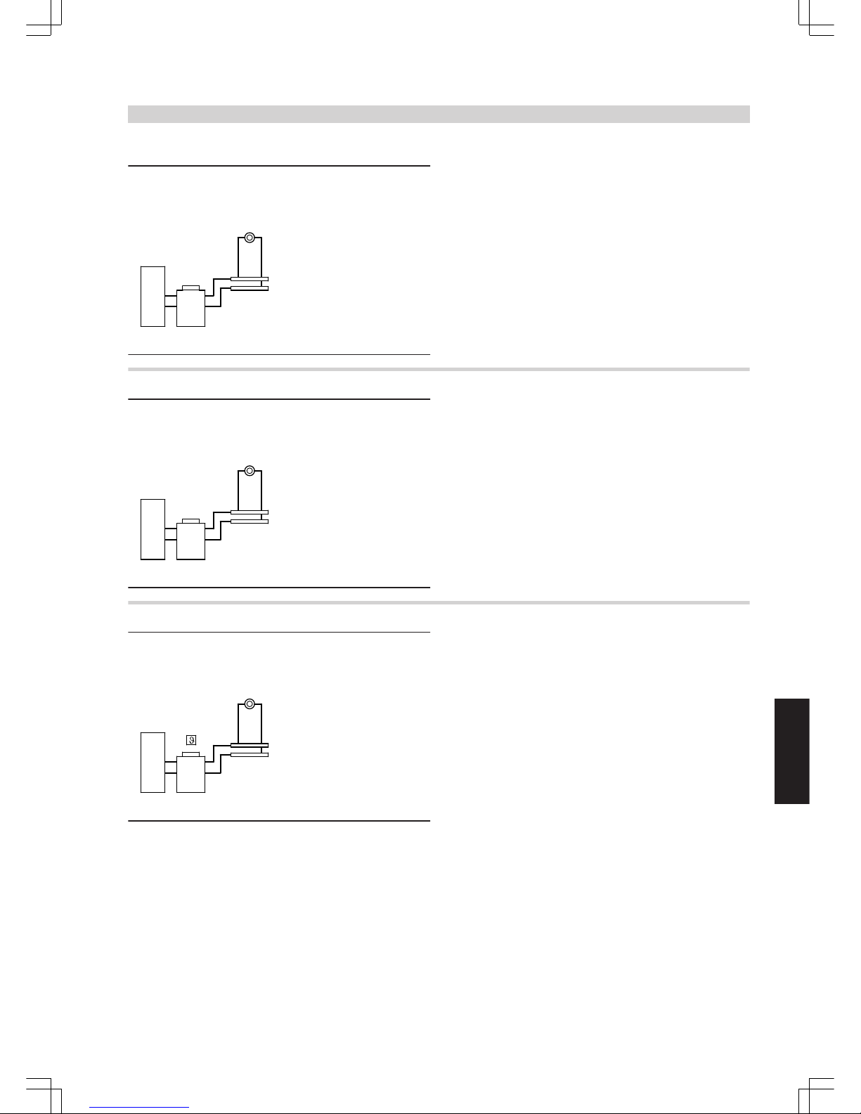
Vitotronic 100, type KC4
Electronic boiler control unit:
■ For constant boiler water temperature
■ For single or two-stage burner
■ For one heating circuit without mixer
■ With digital display
■ With cylinder thermostat
■ With integral diagnostic system
According to the EnEV [Germany], a weather-compensated or room
temperature-dependent control unit with time program for reduced
mode must be installed downstream.
Vitotronic 150, type KB2
Heat demand-dependent, digital boiler control unit:
■ For modulating boiler water temperature
■ With fuzzy logic
■ For one heating circuit without mixer
■ With digital multi-channel time switch with individual and seven-day
programs
■ With cylinder thermostat
■ With integral diagnostic system
Vitotronic 200, type KW4
Weather-compensated, digital boiler control unit:
■ For single boiler systems
■ For one heating circuit without mixer
■ With cylinder thermostat
■ With digital time switch with individual and seven-day programs
■ With separate switching times for central heating, DHW heating and
the DHW circulation pump
■ With integral diagnostic system
■ Function extension (accessories):
To default an additional set boiler water temperature via 0 – 10 V
input
■ Via control module V (accessory):
– External heating program changeover
– Demand with set default value
– Blocking the boiler
– Short term operation of DHW circulation pump
– Fault message input and fault message output
Control units
(cont.)
VITOGAS
VIESMANN
47
5822 428 GB
6
Page 48
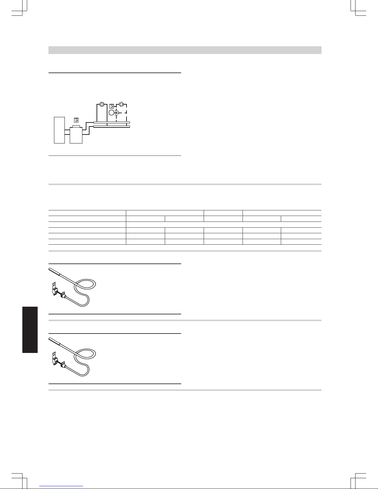
Vitotronic 200, type KW5
M
Weather-compensated, digital boiler and heating circuit control unit:
■ For single boiler systems
■ For a heating circuit without mixer and a heating circuit with mixer
■ With cylinder thermostat
■ With digital time switch with individual and seven-day programs
■ With separate adjustable switching times, set values and heating
curves for the heating circuits
■ With separate switching times for central heating, DHW heating and
the DHW circulation pump
■ With integral diagnostic system
■ Function extension (accessories):
To default an additional set boiler water temperature via 0 – 10 V
input
■ Via control module V (accessory):
– External heating program changeover
– Demand with set default value
– Blocking the boiler
– Short term operation of DHW circulation pump
– Fault message input and fault message output
6.2 Components in the delivered condition
Allocation to control unit types
Vitotronic 100 150 200
Type KC3 KC4 KB2 KW4 KW5
Components
Boiler water temperature sensor x x x x x
Cylinder temperature sensor x x x x
Outside temperature sensor x x
Boiler water temperature sensor
Specification
Lead length 1.6 m, fully wired
IP rating IP 32 to EN 60529; ensure
through appropriate design
and installation
Sensor type Viessmann Pt500
Permissible ambient temperature
– during operation 0 to +130 °C
– during storage and transport -20 to +70 °C
Cylinder temperature sensor
Specification
Lead length 5.8 m, fully wired
IP rating IP 32 to EN 60529; ensure
through appropriate design
and installation
Sensor type Viessmann Pt500
Permissible ambient temperature
– during operation 0 to +90 °C
– during storage and transport –20 to +70 °C
Outside temperature sensor
Installation location:
■ North or north-western wall of the building
■ 2 to 2.5 m above the ground, for multi-storey buildings in the upper
half of the second floor
Connection:
■
2-core lead, length up to 35 m with a cross-section of 1.5 mm2 (copper).
■ Never route this lead immediately next to 230/400 V cables
Control units
(cont.)
48
VIESMANN
VITOGAS
6
5822 428 GB
Page 49
41
66
80
Specification
IP rating IP 43 to EN 60529;
ensure through appropri-
ate design/installation
Sensor type Viessmann Ni500
Permissible ambient temperature during
operation, storage and transport -40 to +70 °C
6.3 Vitotronic 100, type KC3, part no. 7186 582
Specification
Construction
The control unit comprises:
■ ON/OFF switch
■ Temperature controller
DIN TR 116807
or
DIN TR 96808
■ High limit safety cut-out
DIN STB 106005
or
DIN STB 116907
or
DIN STB 98108
■ Wiring chamber
Connection of the burner via a system plug
Connection of external equipment (heating circuit pump, clock thermostat) via terminals
Connection of three-phase consumers via additional contactors
Function
■ Constant control of the boiler water temperature
According to the [German] Energy Savings Order, a weather-compensated or room temperature-dependent control unit with time programming for reduced operation must be installed downstream of the
boiler (see Viessmann pricelist register 18 "Heating circuit control
units").
Control characteristics
■ Two-point control
■ Thermostat with setting range 40 to 75 °C
■ Maximum boiler water temperature limit:
75 °C, adjustable to 87 °C or 95 °C
■ Adjusting the high limit safety cut-out:
110 °C, adjustable to 100 °C
Specification
Rated voltage 230 V~
Rated frequency 50 Hz
Rated current 6 A
Protection class I
IP rating IP 20 D to EN 60529, ensure
through design/installation
Function Type 1B to EN 60730-1
Permissible ambient temperature
– during operation 0 to +40 °C, use in the living
space or boiler room (standard
ambient conditions)
– during storage and transport
−20 to +65 °C
Rated breaking capacity
– Heating circuit pump 4(2) A, 230 V~
–
Burner plug fA
4(2) A, 230 V~
– Total max. 6 A, 230 V~
Delivered condition
■ Boiler water temperature sensor
■ Bag with technical documentation
6.4 Vitotronic 100, type KC4, part no. 7186 569
Specification
Composition
The control unit comprises a standard unit, electronic modules and a
programming unit.
Standard unit:
■ ON/OFF switch
■ Terminals for high limit safety cut-out test
■ Keys for emissions test function
■ Optolink laptop interface
■ Temperature controller
DIN TR 116807
or
DIN TR 96808
■ High limit safety cut-out
DIN STB 106005
or
DIN STB 116907
or
DIN STB 98108
■ Operation and fault displays
■ Plug connection chamber:
– Connection of external equipment via a system plug
– Connection of three-phase consumers via additional contactors
Control units
(cont.)
VITOGAS
VIESMANN
49
5822 428 GB
6
Page 50

Programming unit:
■ Display
■ Keys:
– Program selection
– Boiler water temperature
– DHW temperature
Functions
■ Constant control of the boiler water temperature
■ Electronic maximum and minimum temperature limit
■ Integral diagnostic system
■ Cylinder temperature control unit with priority control (heating circuit
pump OFF).
According to the [German] Energy Savings Order, a weather-compensated or room temperature-dependent control unit with time programming for reduced operation must be installed downstream of the
boiler (see Viessmann pricelist register 18 "Heating circuit control
units").
Control characteristics
■ P-characteristics with two-point output
■ Thermostat for limiting the max. boiler water temperature:
75 °C, adjustable to 87 °C or 95 °C
■ Adjusting the high limit safety cut-out:
110 °C, adjustable to 100 °C
Boiler coding card
For matching to the boiler (supplied with the boiler).
Specification
Rated voltage 230 V~
Rated frequency 50 Hz
Rated current 6 A
Power consumption 5 W
Protection class I
IP rating IP 20 D to EN 60529;
ensure through appropriate design and installation
Function Type 1B to
EN 60 730-1
Permissible ambient temperature
– during operation 0 to +40 °C
Installation in living
spaces or boiler rooms
(standard ambient con-
ditions)
– during storage and transport -20 to +65 °C
Rated capacity of the relay outputs
sÖ
Heating circuit pump
4(2) A 230 V~
sA
Circulation pump for cylinder heating
4(2) A 230 V~
Total sÖ, sA
max. 4 A, 230 V~
fA
Burner 4(2) A 230 V~
lÖ
Burner, two-stage
Only with auxiliary module (part of the
standard delivery for Viessmann boilers)
1(0.5) A 230 V~
Total 6 A 230 V~
Delivered condition
■ Boiler water temperature sensor
■ Cylinder temperature sensor
■ Bag with technical documentation
Heating system with DHW cylinder
Order the circulation pump with check valve for cylinder temperature
control separately.
6.5 Vitotronic 150, type KB2, part no. 7186 570
Specification
Construction
The control unit comprises a standard unit, electronic modules and a
programming unit.
Standard unit:
■ ON/OFF switch
■ Terminals for high limit safety cut-out test
■ Keys for emissions test function
■ Optolink laptop interface
■ Temperature controller
DIN TR 77708
or
DIN TR 116807
■ High limit safety cut-out
DIN STB 106005
or
DIN STB 116907
■ Operation and fault displays
■ Plug connection chamber:
– Connection of external equipment via a system plug
– Connection of three-phase consumers via additional contactors
Programming unit:
■ With digital multi-channel time switch
■ Adjustment and display of temperatures and codes
■ Fault message display
■ Rotary selector for the temperature in standard mode
■ Keys:
– Temperature for reduced mode
– Program selection
– Boiler water temperature
– DHW temperature
■ Time / Date
Functions
■ Heat demand-dependent control of the boiler water temperature
■ Electronic maximum and minimum temperature limit
■ Anti-seizing pump protection
■ Integral diagnostic system
■ Adaptive cylinder temperature control unit with priority control (heating circuit pumps OFF)
According to the Energy Savings Order [Germany], the temperature in
each room must be individually controlled, e.g. through thermostatic
radiator valves.
Control units
(cont.)
50
VIESMANN
VITOGAS
6
5822 428 GB
Page 51

For heating systems with several heating circuits we recommend the
use of other boiler and heating circuit control units (e.g. Vitotronic 200
or Vitotronic 300).
Control characteristics
■ P-characteristics with two-point output
■ Thermostat for limiting the max. boiler water temperature:
75 °C, adjustable to 87 °C or 95 °C
■ Adjusting the high limit safety cut-out:
110 °C, adjustable to 100 °C
Time switch
Digital multi-channel time switch
■ Day and week program, annual calendar
■ Automatic summer/winter time changeover
■ Time, day and standard switching times for central heating and DHW
heating are factory-set
■ Switching times are individually programmable, i.e. up to four switching periods per day
Shortest switching interval: 10 minutes
Power backup: 5 years
Boiler coding card
For matching to the boiler (supplied with the boiler).
Setting heating programs
The heating system frost protection (see frost protection function)
applies to all heating programs.
You can select the following operating programs with the program
keys:
■ Heating and DHW
■ Only DHW
■ Standby mode
Standby mode
No DHW heating takes place in "Standby mode".
In summer, the burner is switched ON if the boiler water temperature
reaches 5 °C and is switched OFF again when the boiler water temperature reaches 42 °C.
The heating circuit pump will be switched OFF from 16 March to
15 October.
From 16 October to 15 March it will then be switched ON on
demand.
Summer mode
("DHW only")
The burner starts only when the DHW cylinder needs reheating (controlled by the cylinder thermostat).
The respective lower boiler water temperature of each boiler is maintained.
Specification
Rated voltage 230 V~
Rated frequency 50 Hz
Rated current 6 A
Power consumption 5 W
Protection class I
IP rating IP 20 D to EN 60529;
ensure through appropriate design/installation
Function Type 1B to
EN 60 730-1
Permissible ambient temperature
– during operation 0 to +40 °C
Installation in living
spaces or boiler rooms
(standard ambient con-
ditions)
– during storage and transport
−20 to +65 °C
Rated capacity of the relay outputs
sÖ
Heating circuit pump
4(2) A 230 V~
sA
Circulation pump for cylinder heating
4(2) A 230 V~
Total sÖ, sA
max. 4 A, 230 V~
fA
Burner 4(2) A 230 V~
Total 6 A 230 V~
Delivered condition
■ Boiler water temperature sensor
■ Cylinder temperature sensor
■ Bag with technical documentation
Heating system with DHW cylinder
Order the circulation pump with check valve for cylinder temperature
control separately.
6.6 Vitotronic 200, type KW4, part no. 7186 571
Specification
Construction
The control unit comprises a standard unit, electronic modules and a
programming unit.
Standard unit:
■ ON/OFF switch
■ Terminals for high limit safety cut-out test
■ Keys for emissions test function
■ Optolink laptop interface
■ Temperature controller
DIN TR 96808
or
DIN TR 116807
■ High limit safety cut-out
DIN STB 106005
or
DIN STB 98108
or
DIN STB 116907
■ Operation and fault displays
■ Plug connection chamber
– Connection of external equipment via a system plug
– Connection of three-phase consumers via additional contactors
Programming unit:
■ With digital time switch
■ Backlit display with plain text support
■ Adjustment and display of temperatures and codes
■ Fault message display
■ Rotary selector for the temperature in standard mode
■ Keys:
– Temperature for reduced mode
– Program selection
– Holiday program
– Party and economy mode
– DHW temperature
– Heating curves for boiler water temperature and flow temperature
– Time / Date
Control units
(cont.)
VITOGAS
VIESMANN
51
5822 428 GB
6
Page 52

Functions
■ Weather-compensated control of the boiler water and/or flow temperature
■ Electronic maximum and minimum temperature limit
■ Demand-dependent heating circuit pump and burner stop (not for
burners on boilers with a low-end boiler water temperature limit)
■ Adjustment of a variable heating limit
■ Anti-seizing pump protection
■ Integral diagnostic system
■ Flue gas temperature monitoring with flue gas temperature sensor
■ Maintenance display
■ Adaptive cylinder temperature control unit with priority control (heating circuit pumps OFF)
■ Auxiliary function for DHW heating (short-term heating to a higher
temperature)
The requirements of DIN EN 12831 for heat load calculation are met.
To reduce the heat-up load, the reduced room temperature will be
raised in case of low outside temperatures. The flow temperature will
be raised for a limited time to reduce the heat-up time after a setback
period.
According to the Energy Savings Order [Germany], the temperature in
each room must be individually controlled, e.g. through thermostatic
radiator valves.
Control characteristics
■ Boiler control unit:
P-characteristics with two-point output when using a burner with
multiple stages
■ Heating circuit control unit:
PI characteristics with three-point output
■ Thermostat for limiting the max. boiler water temperature:
75 °C, adjustable to 87 °C
■ Adjusting the high limit safety cut-out:
110 °C, adjustable to 100 °C
■ Heating curve setting range:
– Slope: 0.2 to 3.5
– Level: -13 to 40 K
– Max. limit: 20 to 130 °C
– Min. limit: 1 to 127 °C
■ Range of the set DHW temperature
10 to 60 °C, may be changed to 10 - 95 °C
Boiler coding card
For matching to the boiler (supplied with the boiler).
Time switch
Digital time switch
■ Day and week program, annual calendar
■ Automatic summer/winter time changeover
■ Automatic function for DHW heating and DHW circulation pump
■ Time, day and standard switching times for central heating, DHW
heating and the DHW circulation pump are factory-set
■ Switching times are individually programmable, i.e. up to four switching periods per day
Shortest switching interval: 10 minutes
Power backup: 5 years
Setting heating programs
The heating system frost protection (see frost protection function)
applies to all heating programs.
You can select the following operating programs with the program
keys:
■ Heating and DHW
■ Only DHW
■ Standby mode
External heating program changeover via control module V.
Summer mode
("DHW only")
The burner starts only when the DHW cylinder needs reheating (controlled by the cylinder thermostat).
The respective low-end boiler water temperature of each boiler is
maintained if necessary.
Frost protection
■ The frost protection function starts when the outside temperature
drops below approx. +1 °C.
With active frost protection, the heating circuit pumps are switched
ON and the boiler water is maintained at the set value for reduced
mode, i.e. at a low-end temperature of approximately. 20 °C. The
allocated temperature is maintained for boilers with a low-end temperature limit.
■ The frost protection function stops when the outside temperature
rises above approx. +3 °C, i.e. the heating circuit pump and burner
will be switched off.
Adjusting the heating curves (slope and level)
The Vitotronic 200 regulates the boiler water temperature in weathercompensated mode (= flow temperature of the heating circuit without
mixer). The boiler water temperature is automatically boosted by
between 0 and 40 K higher than the currently required set flow temperature (delivered condition 8 K).
The flow temperature required to reach a specific room temperature
depends on the heating system and the thermal insulation of the building to be heated.
Adjusting both heating curves matches the boiler water temperature
and the flow temperature to these operating conditions.
The upper boiler water temperature is limited by the thermostat and
the electronic maximum temperature limiter.
0,2
Outside temperature in °C
Boiler water or
flow temperature in °C
Slope
2,4
2,6
2,8
3,0
3,2
3,4
90
80
70
60
50
40
30
0 -5 -10 -15 -20510
2,0
2,2
0,4
0,6
0,8
1,0
1,2
1,4
-30-25
100
110
1,6
1,8
1520
Specification
Rated voltage 230 V~
Rated frequency 50 Hz
Rated current 6 A
Power consumption 5 W
Protection class I
IP rating IP 20 D to EN 60529;
ensure through appropriate design/installation
Function Type 1B to
EN 60 730-1
Control units
(cont.)
52
VIESMANN
VITOGAS
6
5822 428 GB
Page 53

Permissible ambient temperature
– during operation 0 to +40 °C
Installation in living
spaces or boiler rooms
(standard ambient conditions)
– during storage and transport
−20 to +65 °C
Rated capacity of the relay outputs
sÖ
Heating circuit pumps
4(2) A, 230 V~
sA
Circulation pump for cylinder heating
4(2) A, 230 V~
sK
DHW circulation pump 4(2) A, 230 V~
Total sÖ, sA, sK, gS
max. 4 A, 230 V~
fA Burner 4(2) A, 230 V~
lÖ
Burner, two-stage
Only with auxiliary module (part of the
standard delivery for Viessmann boilers) 1(0.5) A,230 V~
Total max. 6 A, 230 V~
Delivered condition
■ Programming unit
■ Outside temperature sensor
■ Boiler water temperature sensor
■ Cylinder temperature sensor
■ Bag with technical documentation
Heating system with DHW cylinder
Order the circulation pump with check valve for cylinder temperature
control separately.
Heating system with heating circuit with mixer
An extension kit (accessories) is required for each heating circuit with
mixer.
6.7 Vitotronic 200, type KW5, part no. 7186 317
Specification
Composition
The control unit comprises a standard unit, electronic modules and a
programming unit.
Standard unit:
■ ON/OFF switch
■ Terminals for high limit safety cut-out test
■ Keys for emissions test function
■ Optolink laptop interface
■ Temperature controller
DIN TR 96808
or
DIN TR 116807
■ High limit safety cut-out
DIN STB 106005
or
DIN STB 98108
or
DIN STB 116907
■ Operation and fault displays
■ Plug connection chamber
– Connection of external equipment via a system plug
– Connection of three-phase consumers via additional contactors
Programming unit:
■ With digital time switch
■ Backlit display with plain text user prompts
■ Adjustment and display of temperatures and codes
■ Fault message display
■ Rotary selector for the temperature in standard mode
■ Keys:
– Temperature for reduced mode
– Program selection
– Holiday program
– Party and economy mode
– DHW temperature
– Heating curves for boiler water temperature and flow temperature
– Heating circuit selection
– Time / Date
Functions
■ Weather-compensated control of the boiler water and/or flow temperature
■ Electronic maximum and minimum temperature limit
■ Demand-dependent heating circuit pump and burner stop (not for
burners on boilers with a low-end boiler water temperature limit)
■ Adjustment of a variable heating limit
■ Anti-seizing pump protection
■ Integral diagnostic system
■ Flue gas temperature monitoring with flue gas temperature sensor
■ Maintenance display
■ Adaptive cylinder temperature control with priority control (heating
circuit pumps off, mixer closed)
■ Auxiliary function for DHW heating (short-term heating to a higher
temperature)
■ Optimised control of a heating circuit, e.g. underfloor heating circuit,
via a flow and return temperature sensor
■ Screed drying, for underfloor heating systems
Control units
(cont.)
VITOGAS
VIESMANN
53
5822 428 GB
6
Page 54

The requirements of DIN EN 12831 for heat load calculation are met.
To reduce the heat-up load, the reduced room temperature will be
raised in case of low outside temperatures. The flow temperature will
be raised for a limited time to reduce the heat-up time after a setback
period.
According to the Energy Savings Order [Germany], the temperature in
each room must be individually controlled, e.g. through thermostatic
radiator valves.
Control characteristics
■ Boiler control unit:
P-characteristics with two-point output when using a burner with
multiple stages
■ Heating circuit control unit:
PI characteristics with three-point output
■ Thermostat for limiting the max. boiler water temperature:
75 °C, adjustable to 87 °C
■ Adjustment of the high limit safety cut-out:
110 °C, adjustable to 100 °C
■ Heating curve setting range:
– Slope: 0.2 to 3.5
–
Level: −13 to 40 K
– Max. limit: 20 to 130 °C
– Min. limit: 1 to 127 °C
– Differential temperature for a heating circuit with mixer: 0 to 40 K
■ Set DHW temperature setting range:
10 to 60 °C; can be changed to 10 to 95 °C
Boiler coding card
For matching to the boiler (supplied with the boiler).
Time switch
Digital time switch
■ Individual day and 7-day program, annual calendar
■ Automatic summer/winter time changeover
■ Automatic function for DHW heating and DHW circulation pump
■ Time, day and standard switching times for central heating, DHW
heating and the DHW circulation pump are factory-set
■ Switching times are individually programmable, i.e. up to four switching periods per day
Shortest switching interval: 10 minutes
Power backup: 5 years
Setting heating programs
The heating system frost protection (see frost protection function)
applies to all heating programs.
You can select the following operating programs with the program
keys:
■ Heating and DHW
■ Only DHW
■ Standby mode
External heating program changeover via control module V.
Summer mode
("DHW only")
The burner starts only when the DHW cylinder needs reheating (controlled by the cylinder thermostat).
The respective low-end boiler water temperature of each boiler is
maintained if necessary.
Frost protection
■ The frost protection function will be started when the outside temperature drops below approx. +1 °C.
With active frost protection, the heating circuit pumps are switched
ON and the boiler water is maintained at the set value for reduced
mode, i.e. at a low-end temperature of approximately. 20 °C. The
allocated temperature is maintained for boilers with a low-end temperature limit.
■ The frost protection function is stopped when the outside temperature rises above approx. +3 °C, i.e. the heating circuit pump and
burner will be switched off.
Adjusting the heating curves (slope and level)
The Vitotronic 200 regulates the boiler water temperature (= flow temperature of the heating circuit without mixer) and the flow temperature
of the heating circuit with mixer, subject to weather conditions. The
boiler water temperature is automatically boosted by between 0 and
40 K higher than the currently required set flow temperature (delivered
condition 8 K).
The flow temperature required to reach a specific room temperature
depends on the heating system and the thermal insulation of the building to be heated.
Adjusting both heating curves matches the boiler water temperature
and the flow temperature to these operating conditions.
The upper boiler water temperature is limited by the thermostat and
the electronic maximum temperature limiter.
0,2
Outside temperature in °C
Boiler water or
flow temperature in °C
Slope
2,4
2,6
2,8
3,0
3,2
3,4
90
80
70
60
50
40
30
0 -5 -10 -15 -20510
2,0
2,2
0,4
0,6
0,8
1,0
1,2
1,4
-30-25
100
110
1,6
1,8
1520
Specification
Rated voltage 230 V~
Rated frequency 50 Hz
Rated current 6 A
Power consumption 5 W
Protection class I
IP rating IP 20 D to EN 60529;
ensure through appropriate design and installation
Function Type 1B to
EN 60 730-1
Permissible ambient temperature
– during operation 0 to +40 °C
Installation in living
spaces or boiler rooms
(standard ambient con-
ditions)
– during storage and transport -20 to +65 °C
Rated capacity of the relay outputs
sÖ
Heating circuit pumps
4(2) A, 230 V~
sA
Circulation pump for cylinder heating
4(2) A, 230 V~
sK
DHW circulation pump 4(2) A, 230 V~
gS Mixer motor 0.2(0.1) A, 230 V~
Total sÖ, sA, sK, gS
max. 4 A, 230 V~
fA Burner 4(2) A, 230 V~
lÖ
Burner, two-stage
Only with auxiliary module (part of the
standard delivery for Viessmann boilers) 1(0.5) A,230 V~
Total max. 6 A, 230 V~
Control units
(cont.)
54
VIESMANN
VITOGAS
6
5822 428 GB
Page 55
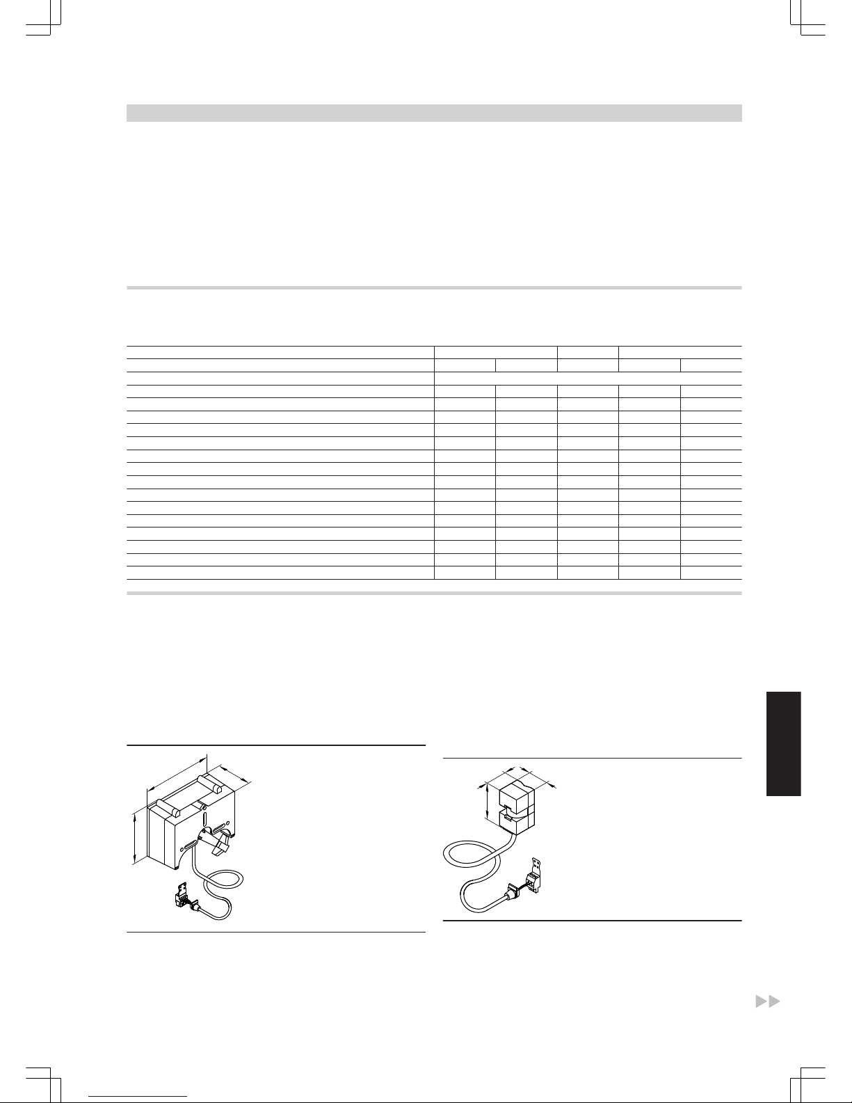
Delivered condition
■ Programming unit
■ Outside temperature sensor
■ Boiler water temperature sensor
■ Cylinder temperature sensor
■ Bag with technical documentation
Heating system with DHW cylinder
Order the circulation pump with check valve for cylinder temperature
control separately.
Heating system with heating circuit with mixer
An extension kit (accessories) is required for each heating circuit with
mixer.
6.8 Control unit accessories
Allocation of accessories according to control unit type
Vitotronic 100 150 200
Type KC3 KC4 KB2 KW4 KW5
Accessories
Extension kit for one heating circuit with mixer x
Contact temperature sensor x
Immersion thermostat x
Contact thermostat x
Vitotrol 100, type UTDB x x
Vitotrol 100, type UTDB-RF x
Vitotrol 300 x x
Room temperature sensor x x
KM BUS distributor x x x
Flue gas temperature sensor x x
Radio clock receiver x x x
Function extension 0–10 V x x
Ext. Extension H5 x x x x
Vitocom 100 x x x
Control module V x x
Extension kit for one heating circuit with mixer
Part no. 7450 650
Components:
■ Mixer motor with connecting cable
■ Plug for the heating circuit pump and flow temperature sensor (contact temperature sensor)
The mixer motor is mounted directly onto the Viessmann mixer DN 20
to 50 and R ½ to 1¼.
Mixer motor
180
130
90
Specification
Cable length 4.2 m, fully wired
Rated voltage 230 V~
Rated frequency 50 Hz
Power consumption 4 W
Protection class II
IP rating IP 42 to EN 60529; ensure
through appropriate design
and installation
Permissible ambient temperature
– during operation 0 to +40 °C
– during storage and transport -20 to +65 °C
Torque 3 Nm
Runtime for 90 ° ∢
120 s
Flow temperature sensor (contact temperature sensor)
40
42
76
Specification
Lead length 5.8 m, fully wired
IP rating IP 32 to EN 60529; ensure
through appropriate design
and installation
Sensor type Viessmann Ni500
Control units
(cont.)
VITOGAS
VIESMANN
55
5822 428 GB
6
Page 56
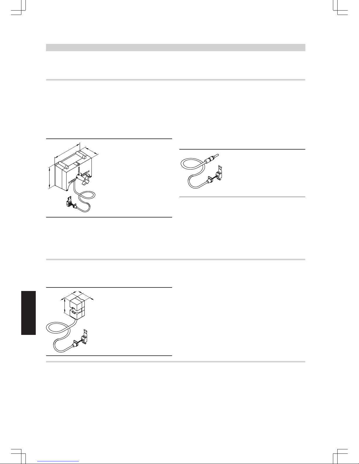
Permissible ambient temperature
– during operation 0 to +120 °C
– during storage and transport -20 to +70 °C
Extension kit for one heating circuit with mixer in conjunction with the Divicon heating circuit distributor
Part no. 7424 959
Components:
■ Mixer motor with connecting cable
■ Plug for heating circuit pump and flow temperature sensor (immersion sensor for installation in the Divicon)
Mixer motor
180
130
90
Specification
Lead length 3.5 m, fully wired
Rated voltage 230 V~
Rated frequency 50 Hz
Power consumption 4 W
Protection class I
IP rating IP 42 to EN 60529; ensure
through appropriate design
and installation
Permissible ambient temperature
– during operation 0 to +40 °C
– during storage and transport -20 to +65 °C
Torque 3 Nm
Runtime for 90 ° ∢
120 s
Flow temperature sensor (immersion sensor)
Specification
Lead length 4.0 m, fully wired
IP rating IP 32 to EN 60529; ensure
through appropriate design
and installation
Sensor type Viessmann Ni500
Permissible ambient temperature
– during operation 0 to +120 °C
– during storage and transport -20 to +70 °C
Contact temperature sensor
Part no. 7183 288
For capturing the flow and return temperature.
40
42
76
Specification
Lead length 5.8 m, fully wired
IP rating IP 32 to EN 60529; ensure
through appropriate design
and installation
Sensor type Viessmann Ni500
Permissible ambient temperature
– during operation 0 to +120 °C
– during storage and transport -20 to +70 °C
Immersion thermostat
Part no. 7151 728
May be used as a maximum temperature limiter for underfloor heating
systems.
The temperature limiter is installed into the heating flow and switches
the heating circuit pump OFF if the flow temperature is too high.
Control units
(cont.)
56
VIESMANN
VITOGAS
6
5822 428 GB
Page 57
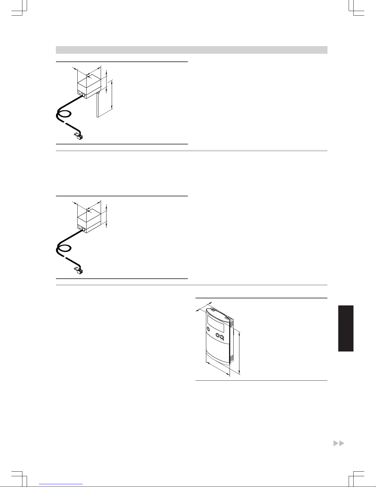
72
130
95
200
Specification
Lead length 4.2 m, fully wired
Setting range 30 to 80 °C
Switching differential max. 11 K
Breaking capacity 6(1.5) A 250 V~
Setting scale inside the casing
Stainless steel sensor well R ½" x 200 mm
DIN reg. no. DIN TR 116807
or
DIN TR 96808
Contact thermostat
Part no. 7151 729
May be used as a maximum temperature limiter for underfloor heating
systems (only in conjunction with metallic pipes).
The temperature limiter is installed into the heating flow and switches
the heating circuit pump OFF if the flow temperature is too high.
72
130
95
Specification
Lead length 4.2 m, fully wired
Setting range 30 to 80 °C
Switching differential max. 14 K
Breaking capacity 6(1.5) A 250V~
Setting scale inside the casing
DIN reg. no. DIN TR 116807
or
DIN TR 96808
Vitotrol 100, type UTDB
Part no. Z007 691
Room temperature controller
■ With switching output (two-point output)
■ With digital time switch
■ With individual and seven-day programs
■ Programming unit with user prompts:
– 3 preselected time programs, individually adjustable
– Constant manual mode with adjustable set room temperature
– Frost protection mode
– Holiday program
■ With selector keys for party and economy mode
Installation in the main living room on an internal wall opposite radiators. Never install inside shelving units, in recesses, or immediately by
a door or heat source (e.g. direct sunlight, fireplace, TV set, etc.).
Operation without power supply (two 1.5 V round alkaline batteries,
type LR6/AA, which run for approx.1.5 years).
Control unit connection:
2-core lead with a cross-section of 0.75 mm2 for 230 V~.
29
130
80
Specification
Rated voltage 3 V–
Battery LR6/AA
Rated breaking capacity of the zero
volt contact
– max. 6(1) A, 230 V~
– min. 1 mA, 5 V–
IP rating IP 20 to EN 60529;
ensure through appropriate
design/installation
Function RS Type 1B to EN 60730-1
Control units
(cont.)
VITOGAS
VIESMANN
57
5822 428 GB
6
Page 58
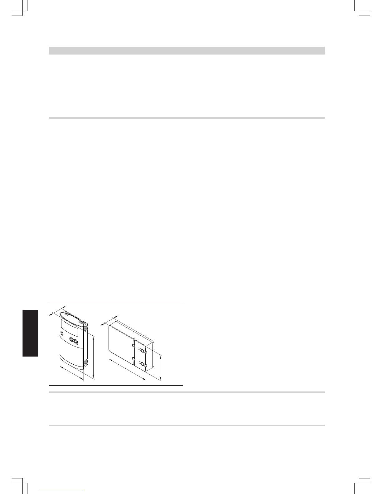
Permissible ambient temperature
– during operation 0 to +40 °C
– during storage and transport –25 to +65 °C
Setting range
– Comfort temperature 10 to 40 °C
– Setback temperature 10 to 40 °C
– Frost protection temperature 5 °C
Power reserve during battery
change 3 min
Vitotrol 100, type UTDB-RF
Part no. Z007 692
Room temperature controller with integral wireless transmitter and one
receiver
■ With digital time switch
■ With individual and seven-day programs
■ Programming unit with user prompts:
– 3 preselected time programs, individually adjustable
– Constant manual mode with adjustable set room temperature
– Frost protection mode
– Holiday program
■ With selector keys for party and economy mode
Installation in the main living room on an internal wall opposite radiators. Never install inside shelving units, in recesses, or immediately by
a door or heat source (e.g. direct sunlight, fireplace, TV set, etc.).
Room temperature controller operation without power supply (two 1.5
V round alkaline batteries, type LR6/AA, which run for approx.
1.5 years).
Receiver with relay state indication.
Connection of the receiver to the control unit (subject to control unit
type):
■
4-core cable with a cross-section of 1.5 mm2 for 230 V~
or
■ 3-core cable without green/yellow core for 230 V~
or
■
2-core lead with a cross section of 0.75 mm2 for LV for the connection
to the control unit, plus an additional 2-core cable for the 230 V~
power supply
130
29
130
30
80
80
Specification, room temperature controller
Rated voltage 3 V–
Transmission frequency 868 MHz
Transmission < 10 mW
Range approx. 25 to 30 m inside
buildings, subject to construction
IP rating IP 20 to EN 60529;
ensure through appropriate
design/installation
Function RS Type 1B to EN 60730-1
Permissible ambient temperature
– during operation 0 to +40 °C
– during storage and transport –25 to +65 °C
Setting range
– Comfort temperature 10 to 40 °C
– Setback temperature 10 to 40 °C
– Frost protection temperature 5 °C
Power reserve during battery
change 3 min
Specification, receiver
Operating voltage 230 V~ ± 10 % 50 Hz
Rated breaking capacity of the zero
volt contact
– max. 6(1) A, 230 V~
– min. 1 mA, 5 V–
IP rating IP 20 to EN 60529;
ensure through appropriate
design/installation
Protection class II to EN 60730-1 subject to cor-
rect installation
Permissible ambient temperature
– during operation 0 to +40 °C
– during storage and transport –25 to +65 °C
Notes regarding room temperature hook-up (RS function) for remote control units
Never activate the RS function for underfloor heating circuits (inertia).
In heating systems with a heating circuit without mixer and heating
circuits with mixer, the RS function must only affect the heating circuit
with mixer.
Information regarding the Vitotrol 200 and 300
For every heating circuit in a heating system, one Vitotrol 200 or one
Vitotrol 300 can be deployed.
Control units
(cont.)
58
VIESMANN
VITOGAS
6
5822 428 GB
Page 59
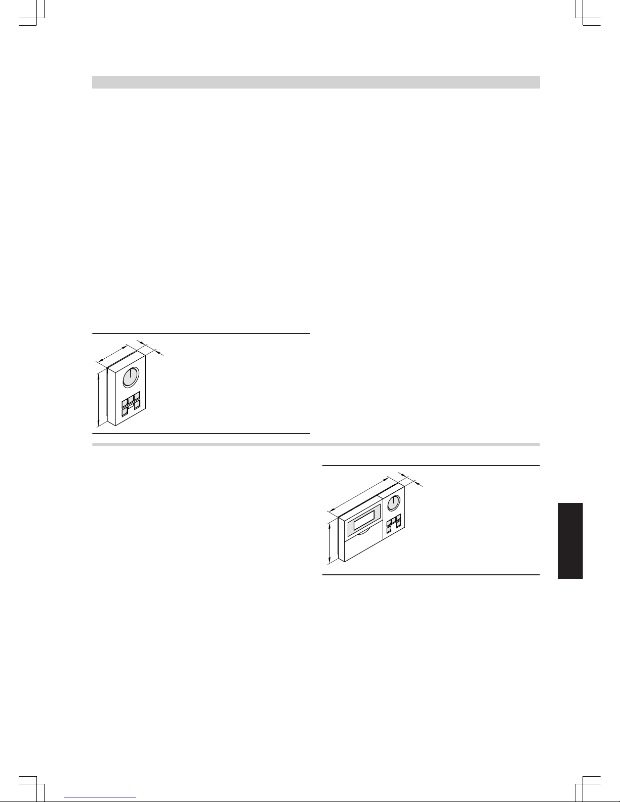
Vitotrol 200
Part no. 7450 017
KM BUS subscriber
The Vitotrol 200 remote control regulates the heating program for one
heating circuit and the required set room temperature in standard
mode, from any room in the house.
The Vitotrol 200 is equipped with backlit heating program selection
keys as well as a party and economy key.
The fault display shows faults on the control unit.
WS function:
Installation anywhere in the building.
RS function:
Installation in the main living room on an internal wall opposite radiators. Never install inside shelf units, recesses, immediately by a door
or heat source (e.g. direct sunlight, fireplace, TV set, etc.).
The integral room temperature sensor captures the actual room temperature and effects any necessary correction of the flow temperature
as well as a rapid heat-up at the start of the heating operation (if
appropriately programmed).
Connection:
■ 2-core lead, length max. 50 m (even if connecting several remote
control units)
■ Never route this lead immediately next to 230/400 V cables
■ LV plug part of the standard delivery
30
75
115
Specification
Power supply via KM BUS
Power consumption 0.2 W
Protection class III
Protection level IP 30 to EN 60529;
safeguard through appropriate design and installa-
tion
Permissible ambient temperature
– during operation 0 to +40 °C
– during storage and transport
−20 to +65 °C
Set room temperature range 10 to 30 °C
adjustable from
3 to 23 °C or
17 to 37 °C
The set room temperature for reduced mode is adjusted at the control
unit.
Vitotrol 300
Part no. 7248 907
KM BUS subscriber
The Vitotrol 300 remote control regulates the required set room temperature for one heating circuit in standard and reduced mode, the
heating program and the switching times for central heating, DHW
heating and the DHW circulation pump.
The Vitotrol 300 provides a backlit display as well as backlit heating
program keys, a party and economy key, automatic summer/winter
time changeover, keys for holiday program, day and time.
WS function:
Installation at any point in the building.
RS function:
Installation in the main living room on an internal wall opposite radiators. Never install inside shelf units, niches, immediately by a door or
heat source (e.g. direct sunlight, fireplace, TV set, etc.).
The integral room temperature sensor captures the actual room temperature and effects any necessary correction of the flow temperature
as well as a rapid heat-up at the start of the heating operation (if suitably encoded).
Connection:
■ 2-core lead, length max. 50 m (even if connecting several remote
control units)
■ Never route this lead immediately next to 230/400 V cables
■ LV plug as standard delivery
30
194
115
Specification
Power supply via KM BUS
Power consumption 0.5 W
Protection class III
Protection IP 30 to EN 60529;
safeguard through appropriate design and installa-
tion
Permissible ambient temperature
– during operation 0 to +40 °C
– during storage and transport -20 to +65 °C
Set room temperature range
– for standard mode 10 to 30 °C
adjustable to
3 to 23 °C or
17 to 37 °C
– for reduced mode 3 to 37 °C
Control units
(cont.)
VITOGAS
VIESMANN
59
5822 428 GB
6
Page 60
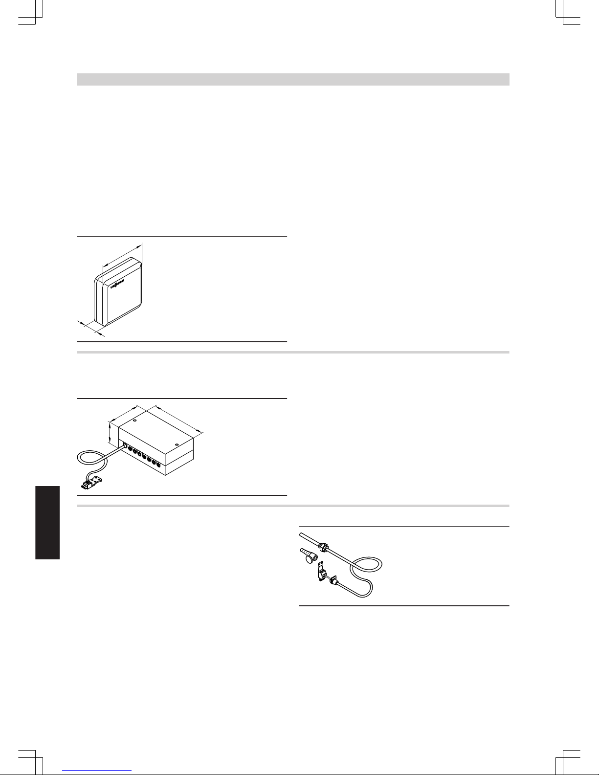
Room temperature sensor
Part no. 7408 012
Separate room temperature sensor as supplement to the Vitotrol 200
and 300; to be used if the Vitotrol 200 or 300 cannot be installed inside
the main living room or in a suitable position where the unit can capture
and adjust the temperature.
Installation in the main living room on an internal wall opposite radiators. Never install inside shelving units, in recesses, or immediately by
a door or heat source (e.g. direct sunlight, fireplace, TV set, etc.).
Connect the room temperature sensor to the Vitotrol 200 or 300.
Connection:
■
2-core lead with a cross-section of 1.5 mm2 (copper)
■ Lead length from the remote control up to 30 m
■ Never route this lead immediately next to 230/400 V cables
20
80
□
Specification
Protection class III
IP rating IP 30 to EN 60529;
ensure through appropri-
ate design/installation
Sensor type Viessmann Ni500
Permissible ambient temperature
– during operation 0 to +40 °C
– during storage and transport
−20 to +65 °C
KM BUS distributor
Part no. 7415 028
For the connection of 2 to 9 devices to the Vitotronic KM BUS.
217
130
84
Specification
Lead length 3.0 m, fully wired
Protection IP 32 to EN 60529;
safeguard through appro-
priate design and installa-
tion
Permissible ambient temperature
– during operation 0 to +40 °C
– during storage and transport
-20 to +65 °C
Flue gas temperature sensor
Part no. 7450 630
For scanning the flue gas temperature, flue gas temperature monitoring and maintenance indication, if the set temperature has been exceeded.
With threaded cone.
Installation on the flue pipe. The distance from the boiler must be
approx. 1.5 times the flue pipe diameter, measured from the boiler
edge (back) to the chimney stack.
■ Condensing boilers with Viessmann balanced flue system:
Order the balanced flue pipe with connector for the flue gas temperature sensor separately.
■ For condensing boilers with on-site flue pipe:
The aperture required for the flue pipe installation must be designed
and approved by the supplier. Install the flue gas temperature sensor
into a stainless steel sensor well (on-site provision).
Specification
Lead length 3.8 m, fully wired
IP rating IP 60 to EN 60529; ensure
through appropriate design
and installation
Sensor type Viessmann Pt500
Permissible ambient temperature
– during operation 0 to +600 °C
– during storage and transport -20 to +70 °C
Control units
(cont.)
60
VIESMANN
VITOGAS
6
5822 428 GB
Page 61
Radio clock receiver
Part no. 7450 563
For receiving the DCF 77 time signal (location: Mainflingen near Frankfurt/Main).
Radio controlled setting of time and date.
Install on an outside wall, facing the transmitter. The reception may be
reduced by metallic elements in the building structure, e.g. steel reinforced concrete, neighbouring buildings and sources of electro-magnetic interference, e.g. HV and public transport lines.
Connection:
■
2-core lead, length up to 35 m with a cross-section of 1.5 mm2(copper)
■ Never route this lead immediately next to 230/400 V cables.
41
66
80
Function extension 0–10 V
Part no. 7174 718
KM BUS subscriber
Including cables equipped with plug fÖ and
aVG
.
217
130
84
Specification
Rated voltage 230 V ~
Rated frequency 50 Hz
Power consumption 1 W
Rated breaking capacity of the relay output
4(2) A 230 V~
Protection IP 30 to EN 60529
safeguard through appropriate design and installa-
tion
Permissible ambient temperature
– during operation 0 to +40 °C
– during storage and transport -20 to +65 °C
Functions in connection with the function extension 0 – 10 V (accessory)
■
0 – 10 V input aVF:
Defaulting an additional set boiler water temperature
■
Switching output aBJ (zero volt contact)
Night contact (to signal reduced mode and to regulate the heating
circuit pump to a lower speed)
External extension H5
Part no. 7199 249
Function extension inside the casing.
With plug
aBÖ
for the following functions:
■ External demand and blocking
or
Connection of a flue gas damper
■ Connection of additional safety equipment
Cable 2.0 m long with plugs "X12" and fA for connection to the control
unit.
217
130
84
Specification
Rated voltage 230 V–
Rated frequency 50 Hz
Rated current 6 A
Protection class I
Protection IP 20 to EN 60529;
safeguard through appropriate
design and installation
Permissible ambient temperature
– during operation 0 to +40 °C
– during storage and transport -20 to +65 °C
Control units
(cont.)
VITOGAS
VIESMANN
61
5822 428 GB
6
Page 62
Vitocom 100, type GSM
■ Without SIM card
Part no. Z004594
■ With contract SIM card for the operation of the Vitocom 100 via
mobile phone
Part no. Z004615
Note
For further information regarding the conditions of contract, see the
Viessmann pricelist.
Functions:
■ Remote switching via GSM mobile phone networks
■ Remote scanning via GSM mobile phone networks
■ Remote monitoring via SMS to 1 or 2 mobile phones
■ Remote monitoring of additional systems via digital input (230 V)
Configuration:
Mobile phones via SMS
Standard delivery:
■ Vitocom 100 (subject to order with or without SIM card)
■ Power supply cable with Euro plug (2.0 m long)
■ GSM aerial (3.0 m long), magnetic foot and adhesive pad
■ KM BUS cable (3.0 m long)
On-site requirements:
Good reception for GSM communication of the selected mobile phone
operator.
Total length of all KM BUS subscriber cables up to 50 m.
72
130
50
Specification
Rated voltage 230 V ~
Rated frequency 50 Hz
Rated current 15 mA
Power consumption 4 W
Protection class II
Protection IP 41 to EN 60529; safeguard
through appropriate design
and installation
Function Type 1B to EN 60 730-1
Permissible ambient temperature
– during operation 0 to +55 °C
Installation in living spaces or
boiler rooms (standard ambi-
ent conditions)
– during storage and transport -20 to +85 °C
On-site connection
Fault input DE 1 230 V~
Control module V
Part no. 7143 513
KM BUS user; may only be used as an alternative to the function
extension 0—10 V.
The following function extensions of the control unit may be used using
the control module V:
■ External burner start for a minimum boiler water temperature (affects
the burner and possibly pumps and mixers), for example swimming
pool or ventilation demand
■ External burner blocking
■ Changeover of heating/operating program via external contacts for
each heating circuit separately
■ External fault messaging
■ Central fault message output (zero volt switching contact)
■ Connection for the short-term operation of the DHW circulation pump
(e.g. through a push button).
217
130
84
Specification
Lead length: 3.0 m, ready-to-plug-in
Protection IP 32 to EN 60529; safe-
guard through appropriate
design and installation
Permissible ambient temperature
– during operation 0 to +40 °C
– during storage and transport -20 to +65 °C
Control units
(cont.)
62
VIESMANN
VITOGAS
6
5822 428 GB
Page 63

C
Contact thermostat...........................................................................57
E
EnEV..........................................................................................52, 54
F
Function extension...........................................................................61
H
Heating circuit distributor
■ Modular-Divicon............................................................................35
I
Immersion thermostat......................................................................56
K
KM BUS distributor...........................................................................60
O
Operating conditions....................................................................5, 11
Outside temperature sensor.............................................................48
P
Plastic pipework...............................................................................45
R
Room temperature controller.....................................................57, 58
Room temperature sensor...............................................................60
Room thermostat........................................................................57, 58
S
Safety assembly to DIN 1988...........................................................35
T
Temperature sensor
■ Outside temperature.....................................................................48
■ Room temperature........................................................................60
Thermostat
■ Contact temperature.....................................................................57
■ Immersion temperature.................................................................56
Time switch................................................................................52, 54
U
Underfloor heating systems.............................................................45
V
Vitocom
■ 100, type GSM..............................................................................62
Vitotrol
■ 200................................................................................................59
■ 300................................................................................................59
■ UTDB............................................................................................57
■ UTDB-RF......................................................................................58
Keyword index
VITOGAS
VIESMANN
63
5822 428 GB
Page 64

64
VIESMANN
VITOGAS
5822 428 GB
Printed on environmentally friendly,
chlorine-free bleached paper
Subject to technical modifications.
Viessmann Limited
Hortonwood 30, Telford
Shropshire, TF1 7YP, GB
Telephone: +44 1952 675000
Fax: +44 1952 675040
E-mail: [email protected]
Viessmann Werke GmbH&Co KG
D-35107 Allendorf
Telephone: +49 6452 70-0
Fax: +49 6452 70-2780
www.viessmann.com
 Loading...