

Page 1
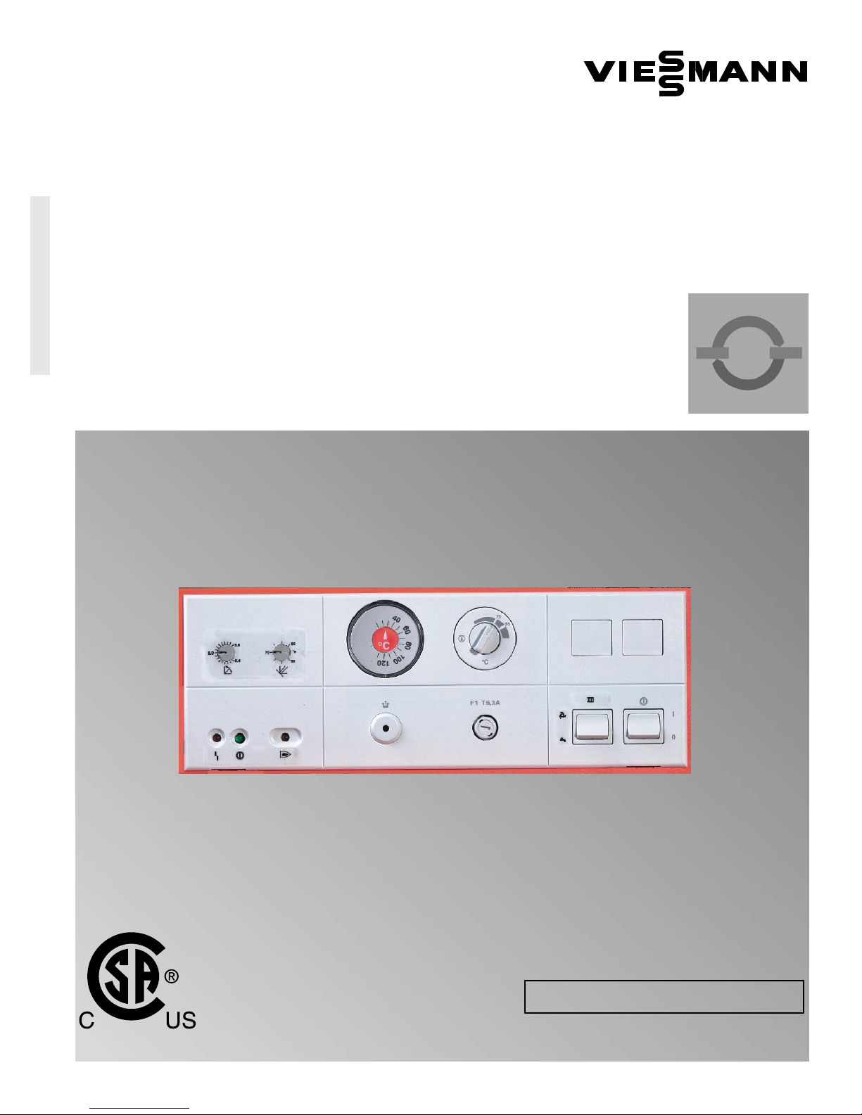
Installation, Start-up
and Service Instructions
Vitotronic 100
Model KW10
Boiler control unit
for modulating temperature heating systems
Part No. 7133 375
Please file in Service Binder
VITOTRONIC 100
Certified as a component part
of Viessmann boilers only
5167 483 v1.4 08/2010
IMPORTANT
Read and save these instructions
for future reference.
Page 2
Safety, Installation and Warranty Requirements
Safety, Installation and Warranty Requirements
Please ensure that this manual is read and understood before commencing installation. Failure to comply with the issues listed
below and details printed in this manual can cause product/property damage, severe personal injury, and/or loss of life. Ensure all
requirements below are understood and fulfilled (including detailed information found in manual subsections).
H Licensed professional heating
contractor
The installation, adjustment, service,
and maintenance of this equipment
must be performed by a licensed
professional heating contractor.
"
Please see sections
entitled “Safety” and
“Important Regulatory and
Installation Requirements”.
H Product documentation
Read all applicable documentation
before commencing installation. Store
documentation near boiler in a readily
accessible location for reference in the
future by service personnel.
"
For a listing of applicable
literature, please see
section entitled “Important
Regulatory and Installation
Requirements”.
H Advice to owner
Once the installation work is complete,
the heating contractor must familiarize
the system operator/ultimate owner
with all equipment, as well as safety
precautions/requirements, shut-down
procedure, and the need for
professional service annually before the
heating season begins.
H Warranty
Information contained in this and
related product documentation must be
read and followed. Failure to do so
renders warranty null and void.
2
5167 483 v1.4
Page 3

Page
Contents
Important Precautions
General Information
Heating System
Electrical Connections
Altering Settings
Safety 4
Important Regulatory and Installation Requirements 5
About these Installation Instructions 5
Valid for ... 5
. . . . . . . . . . . . . . . . . . . . . . . . . . . . . . . .. . . . . . . . . .. . . . . . . . .. . . . .. . . . . . . . . .. . . . . . . . . .. . . . . . . . . .. . . . . . . . ..
. . . .
. . . . . . . . . . . . . . . . . . . . . . . . . . . . . . . .. . .
. . . . . . . . . . . . . . . . . . . . . . . . . . . . . . . .. . . . . . . . . .. . . . . . . . .. . . . .. . . . . . . . . .. . . . . . . . . .. . . . . . . . . .
System Configuration
One direct-connected heating circuit
without mixing valve 6
Opening the Control 7
Overview 8
. . . . . . . . . . . . . . . . . . . . . . . . . . . . . . . .. . . . . . . . . .. . . . . . . . .. . . . .. . . . . . . . . .. . . . . . . . . .. . . . . . . . . .. . . .
Routing Cabling 9
Power Supply 9
. . . . . . . . . . . . . . . . . . . . . . . . . . . . . . . .. . . . . . . . . .. . . . . . . . .. . . . .. . . . . . . . . .. . . . . . . . . .. . . . .
Burner Connection 10
Room Thermostat Connection 10
Pump Connection 11
Installation of Outdoor Temperature Sensor 12
Fixed High Limit 13
Testing the FHL 13
Adjustable High Limit 14
. . . . . . . . . . . . . . . . . . . . . . . . . . . . . . . .. . . . . . . . . .. . . . . . . . .. . . . .. . . . . . . . . .
. . . . . . . . . . . . . . . . . . . . . . . . . . . . . . . .. . . . . . . . . .. . . . . . . . .. . . . .. . . . . . . . . .. .
. . . . . . . . . . . . . . . . . . . . . . . . . . . . . . . .. . . . . . . . . .. . . . . . . . .. . . . .. . . . . . . . . .. . . . . . . . . ..
. . . . . . . . . . . . . . . . . . . . . . . . . . . . . . . .. . . . . . . . . .. . . . . . . . .. . . . .. . . . . . . . . .. . . . .
. . . . . . . . . . . . . . . . . . . . . . . . . . . . . . . .. . . . . . . . . .. . . . . .
. . . . . . . . . . . . . . . . . . . . . . . . . . . . . . . .. . . . . . . . . .. . . . . . . . .. . . . .. . . . . . . . . .. . . . . . .
. . . . . . . . . . . . . . . . . . . .
. . . . . . . . . . . . . . . . . . . . . . . . . . . . . . . .. . . . . . . . . .. . . . . . . . .. . . . .. . . . . . . . . .. . . . . . . . . .
. . . . . . . . . . . . . . . . . . . . . . . . . . . . . . . .. . . . . . . . . .. . . . . . . . .. . . . .. . . . . . . . . .. . . . . . . . . .
. . . . . . . . . . . . . . . . . . . . . . . . . . . . . . . .. . . . . . . . . .. . . . . . . . .. . . . .. . . . . . . . .
Appendix
Start-up
Troubleshooting
Additional Information
Dip Switch Settings 15
Altering the Indoor/Outdoor Control Settings 16
Slope adjustment 16
Warm weather shut-down adjustment 17
After Installation ... 18
Checklist 18
. . . . . . . . . . . . . . . . . . . . . . . . . . . . . . . .. . . . . . . . . .. . . . . . . . .. . . . .. . . . . . . . . .. . . . . . . . . .. . . . . . . . . .. . . .
Service Binder 18
Start-up Instructions 18
Check all connections 18
Set fixed high limit and adjustable high limit 18
Set correct operational settings on control 18
Diagnostics 19
. . . . . . . . . . . . . . . . . . . . . . . . . . . . . . . .. . . . . . . . . .. . . . . . . . .. . . . .. . . . . . . . . .. . . . . . . . . .. . . . . . . . . .
. . . . . . . . . . . . . . . . . . . . . . . . . . . . . . . .. . . . . . . . . .. . . . . . . . .. . . . .. . . . . . . . . .. .
. . . . . . . . . . . . . . . . . . .
. . . . . . . . . . . . . . . . . . . . . . . . . . . . . . . .. . . . . . . . . .. . . . . . . . .. . . . .. . . . . . . . . .. . . . . . . . .
. . . . . . . . . . . . . . . . . . . . . . . . . . . . . . . .
. . . . . . . . . . . . . . . . . . . . . . . . . . . . . . . .. . . . . . . . . .. . . . . . . . .. . . . .. . . . . . . . . .. . . .
. . . . . . . . . . . . . . . . . . . . . . . . . . . . . . . .. . . . . . . . . .. . . . . . . . .. . . . .. . . . . . . . . .. . . . . . . . . .. . . .
. . . . . . . . . . . . . . . . . . . . . . . . . . . . . . . .. . . . . . . . . .. . . . . . . . .. . . . .. . . . . . . . . ..
. . . . . . . . . . . . . . . . . . . . . . . . . . . . . . . .. . . . . . . . . .. . . . . . . . .. . . . .. . . . . . . .
. . . . . . . . . . . . . . . . . . .
. . . . . . . . . . . . . . . . . . . . . . . .
(for qualified service personnel only)
Failure, Cause, Correction 19
Electrical connections and sequence of operation 20
. . . . . . . . . . . . . . . . . . . . . . . . . . . . . . . .. . . . . . . . . .. . . . . . . . .. . . . .
. . . . . . . . .
Replacement Components
(for qualified service personnel only) 22
Boiler Protection 24
Parts List 28
Wiring Diagram 29
Technical Data 30
Protocol 30
. . . . . . . . . . . . . . . . . . . . . . . . . . . . . . . .. . . . . . . . . .. . . . . . . . .. . . . .. . . . . . . . . .. . . . . . . . . .. . . . . . . . . .. . . . . . .
. . . . . . . . . . . . . . . . . . . . . . . . . . . . . . . .. . . . . . . . . .. . . . . . . . .. . . . .. . . . . . . . . .. . . . . . . . . ..
. . . . . . . . . . . . . . . . . . . . . . . . . . . . . . . .. . . . . . . . . .. . . . . . . . .. . . . .. . . . . . . . . .. . . . . . . . . .. . . . . . . . . .. . . . .
. . . . . . . . . . . . . . . . . . . . . . . . . . . . . . . .. . . . . . . . . .. . . . . . . . .. . . . .. . . . . . . . . .. . . . . . . . . .. . .
. . . . . . . . . . . . . . . . . . . . . . . . . . . . . . . .. . . . . . . . . .. . . . . . . . .. . . . .. . . . . . . . . .. . . . . . . . . .. . . .
. . . . . . . . . . . . . . . . . . . . . . . . . . . . . . . .. . .
5167 483 v1.4
3
Page 4
Important Precautions
Safety
Take note of all symbols and notations intended to draw attention to potential hazards or important product information.
These include ”WARNING,” ”CAUTION,” and ”IMPORTANT.” See page 5 for details.
Approvals
Viessmann boilers, burners and
controls are approved for sale in North
America by CSA International.
Codes
The installation of this unit shall be in
accordance with local codes. In the
absence of local codes, use:
H CSA C22.1 Part 1 and/or local codes
in Canada
H National Electrical Code ANSI/NFPA
70 in the U.S.
Always use latest editions of codes.
Working on the equipment
The installation, adjustment, service,
and maintenance of this product must
be done by a licensed professional
heating contractor who is qualified and
experienced in the installation, service,
and maintenance of hot water boilers.
There are no user serviceable parts on
the boiler, burner, or control.
Please carefully read this manual prior
to attempting installation. Any
warranty is null and void if these
instructions are not followed.
For information regarding other
Viessmann System Technology
componentry, please reference
documentation of the respective
product.
We offer frequent installation and
service seminars to familiarize our
partners with our products. Please
inquire.
The completeness and functionality of
field supplied electrical controls and
components must be verified by the
heating contractor. These include low
water cut-offs, flow switches (if used),
staging controls, pumps, motorized
valves, air vents, thermostats, etc.
Ensure main power supply to
equipment, the heating system, and all
external controls has been deactivated.
Close main oil or gas supply valve.
Take precautions in both instances to
avoid accidental activation of power
during service work.
Technical literature
Literature applicable to all aspects of
the Vitotronic 100:
- Technical Data Manual
- Installation, Start-up
and Service Instructions
- Operating Instructions
and User’s Information Manual
- Instructions of other Viessmann
products utilized and installed
- Installation codes mentioned
in this manual
WARNING
Turn off electric power
supply before
servicing. Contact with
live electric
components can cause
shock or loss of life.
Leave all literature at the installation
site and advise the system
operator/ultimate owner where the
literature can be found. Contact
Viessmann for additional copies.
4
5167 483 v1.4
Page 5
Important Precautions / General Information
Important Regulatory and Installation Requirements
Power supply
Install power supply in accordance with
the regulations of the authorities
having jurisdiction or, in the absence of
such requirements, in accordance with
National Codes. Viessmann
recommends the installation of a
disconnect switch to the 120 VAC
power supply outside of the boiler
room. The installer must provide
maximum 15 A overcurrent protection
for the 120 VAC power supply (fuse or
circuit breaker).
Note on connecting external
“potential-free” contacts to the
Vitotronic 100 control’s 24 VAC
thermostat connections
Ensure that all contacts have sufficient
insulation clearance to live parts and
are certified for these applications.
A room thermostat or other
potential-free contact (i.e. end switch
of a zone valve) must be connected to
the Vitotronic 100 thermostat
connections.
Working with an open control
No static discharge to the internal
componentry must ever occur when
working with opened control
equipment.
About these Installation Instructions
Take note of all symbols and notations intended to draw attention to potential hazards or important product information.
These include ”WARNING”, ”CAUTION”, and ”IMPORTANT”. See below.
Warnings draw your attention to the
WARNING
Indicates an imminently hazardous
situation which, if not avoided, could
result in death, serious injury or
substantial product/property damage.
presence of potential hazards or
important product information.
Valid for ...
Cautions draw your attention to the
CAUTION
Indicates an imminently hazardous
situation which, if not avoided, may
result in minor injury or
product/property damage.
IMPORTANT
Applies to Vitotronic 100, Model KW10:
Order No. 7133 375, starting with serial no. V00101
This control shall only be installed with the Vitola 200, Vitorond 200,
Vitogas 050, RS Series, or with a Vitogas 100 hot water heating boiler.
presence of potential hazards or
important product information.
Helpful hints for installation,
operation or maintenance which
pertain to the product.
This symbol indicates that additional,
pertinent information is to be found in
column three.
This symbol indicates that other
instructions must be referenced.
5167 483 v1.45167 483 v1.4
5
Page 6
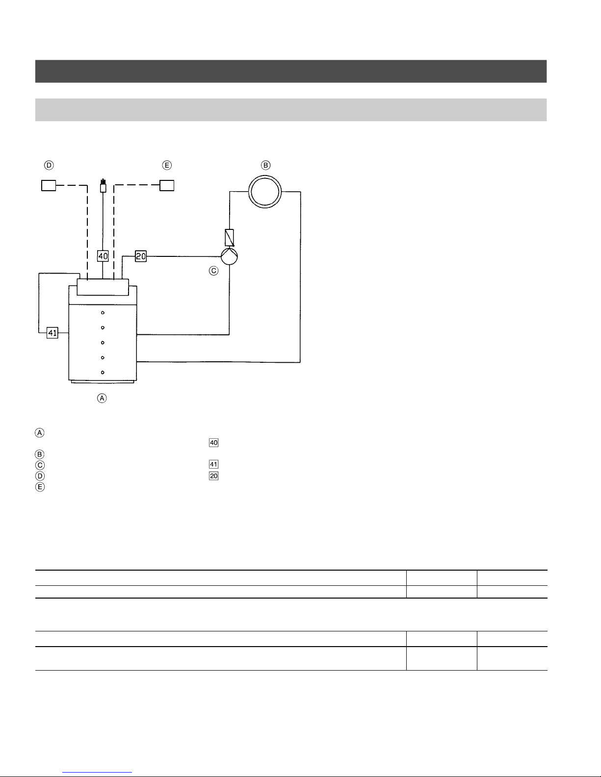
Heating System
System Configuration
One direct-connected heating circuit without mixing valve
TH OTS
Boiler with
Vitotronic 100, Model KW10
Heating circuit
System pump
Room thermostat
Outdoor temperature sensor
Required equipment
Description Quantity Order No.
Vitotronic 100, Model KW10 1 7133 375
Optional equipment
Description Quantity Order No.
DHW Pump Module for domestic hot water production using a
Viessmann Vitocell indirect-fired domestic hot water storage tank
120 VAC connections
Power supply cord,
120 VAC, 60 Hz
Burner connection
Pump connection
(used with:
Vitorond 200,
Vitogas 050, RS Series, and
Vitogas 100 boilers only)
1 9543 431
6
5167 483 v1.4
Page 7
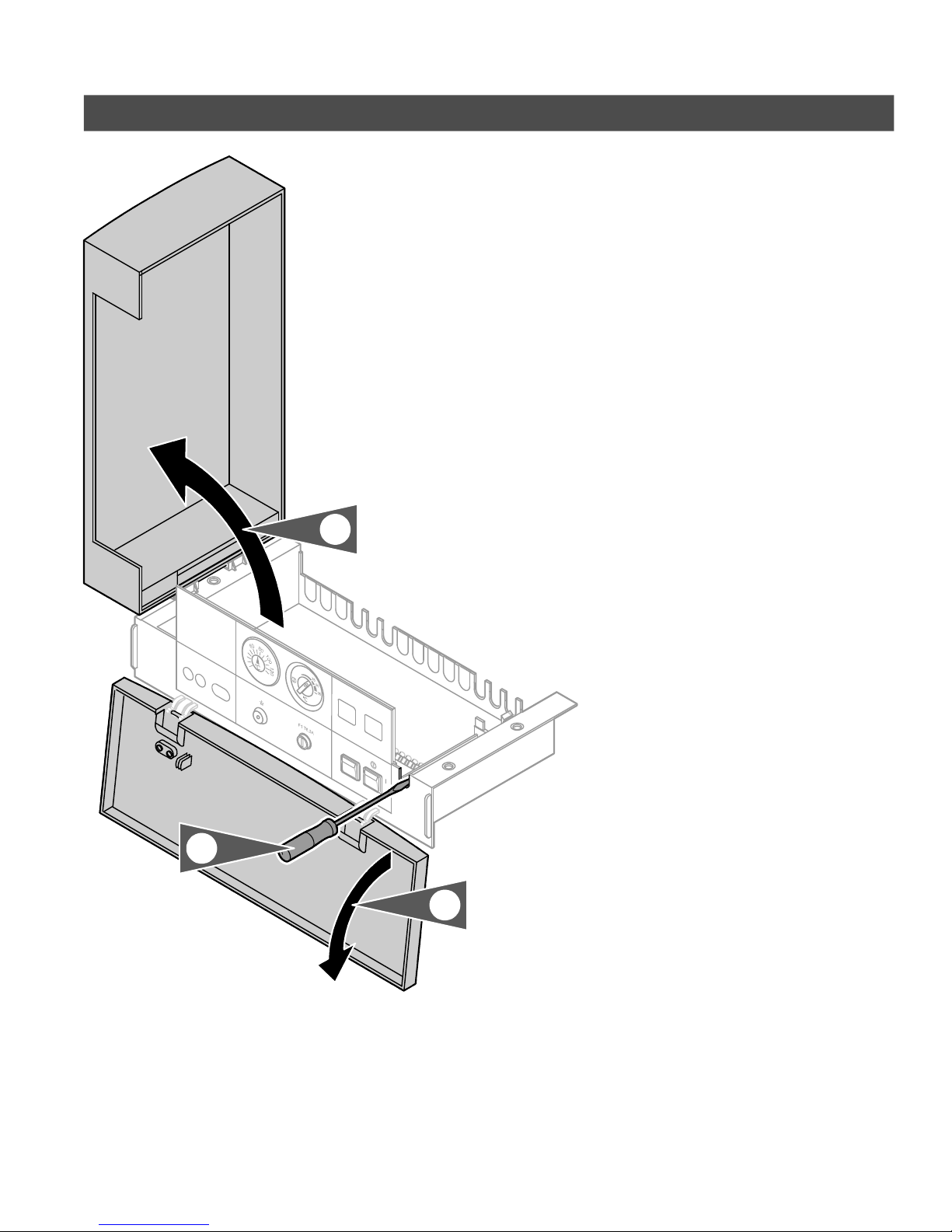
Opening the Control
Electrical Connections
1. Open front cover.
2. Carefully unlock control top cover
using a screw driver and flip open
top cover.
2.
2.
1.
5167 483 v1.4
7
Page 8
Electrical Connections
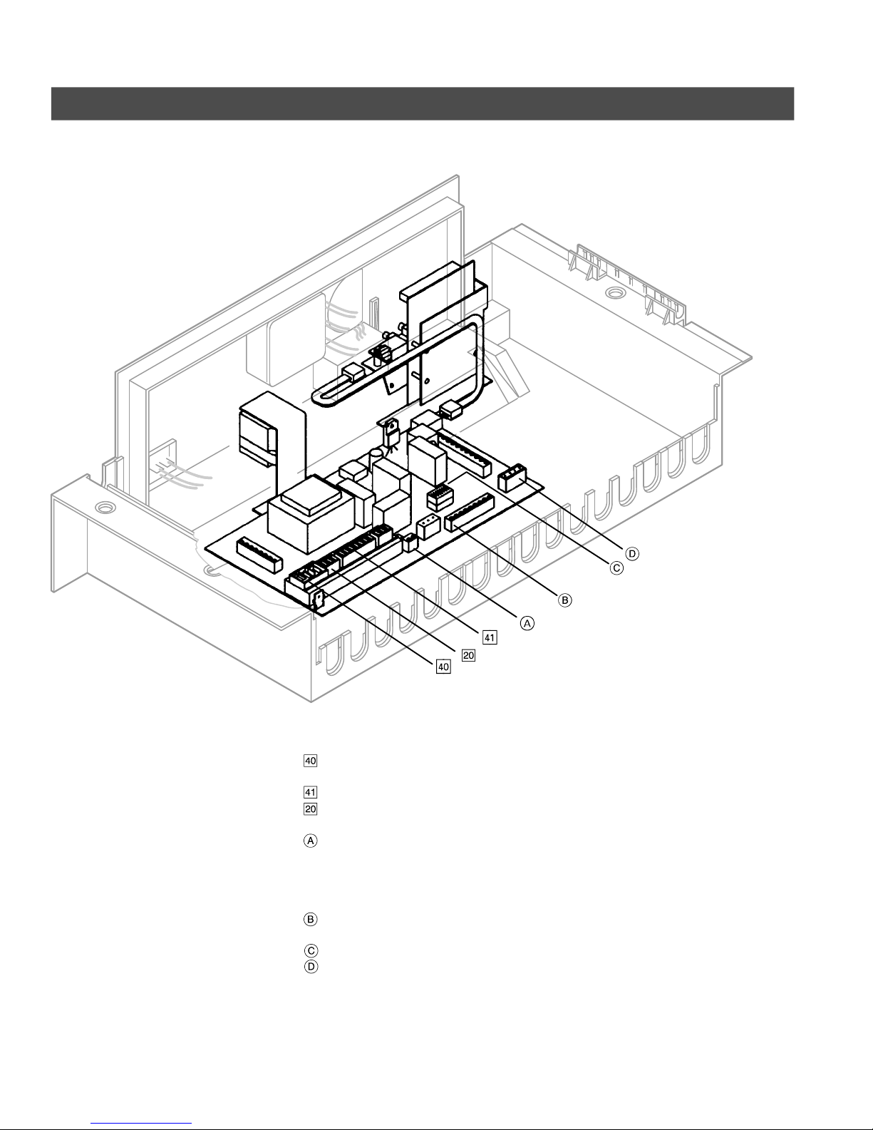
Overview
The control is pictured from the rear.
8
120 VAC connections
for power supply cord
120 VAC, 60 Hz
for burner connection
Pump connection
FHL test connection
A B Test
24 VAC connections
Room thermostat connection
X2.1, X2.2
Dip switches
Outdoor temperature sensor
(field wired) and
boiler sensor connection
1 / 3
5167 483 v1.4
Page 9
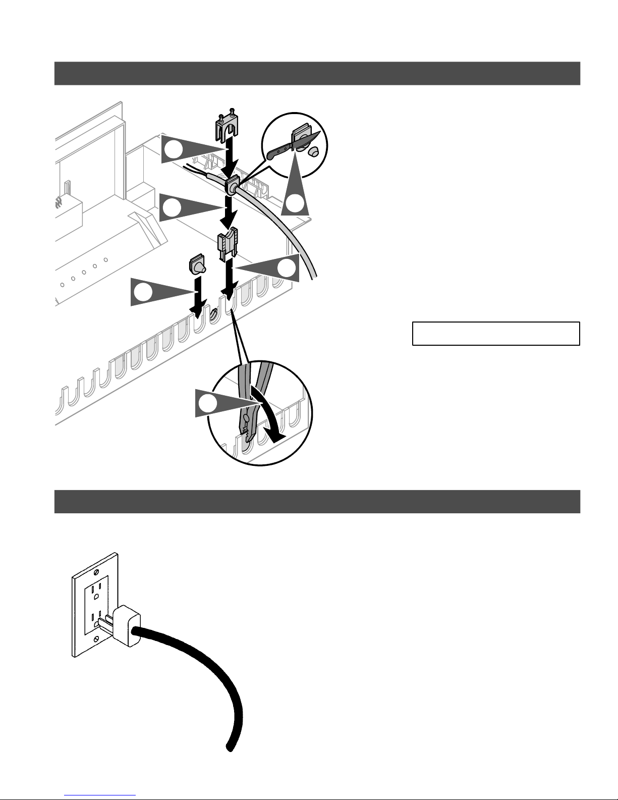
Routing Cabling
Electrical Connections
Strain relief clamps are located in the
fittings package supplied with the
control.
6.
5.
4.
1.
2.
3.
1. Remove breakouts as necessary.
2. Mount lower portion of strain relief
clamp.
3. Cut rubber grommet (if applicable).
4. Insert rubber grommet in strain
relief and mount strain relief.
5. Fasten top portion of strain relief.
6. Close off openings in the control
which are not being used.
IMPORTANT
Rubber grommets may already be
mounted on cabling.
Power Supply
5167 483 v1.4
Follow instructions under Important
Regulatory and Installation
Requirements.
1. Feed the power supply cord with
3-prong molded plug through rear
top panel wiring gate of the boiler.
2. Slide cable into the strain relief and
secure with strain relief set screw.
3. Plug power supply cord into
receptacle. Ensure receptacle is
designated for the heating system
only.
9
Page 10
Electrical Connections
ventsystem.
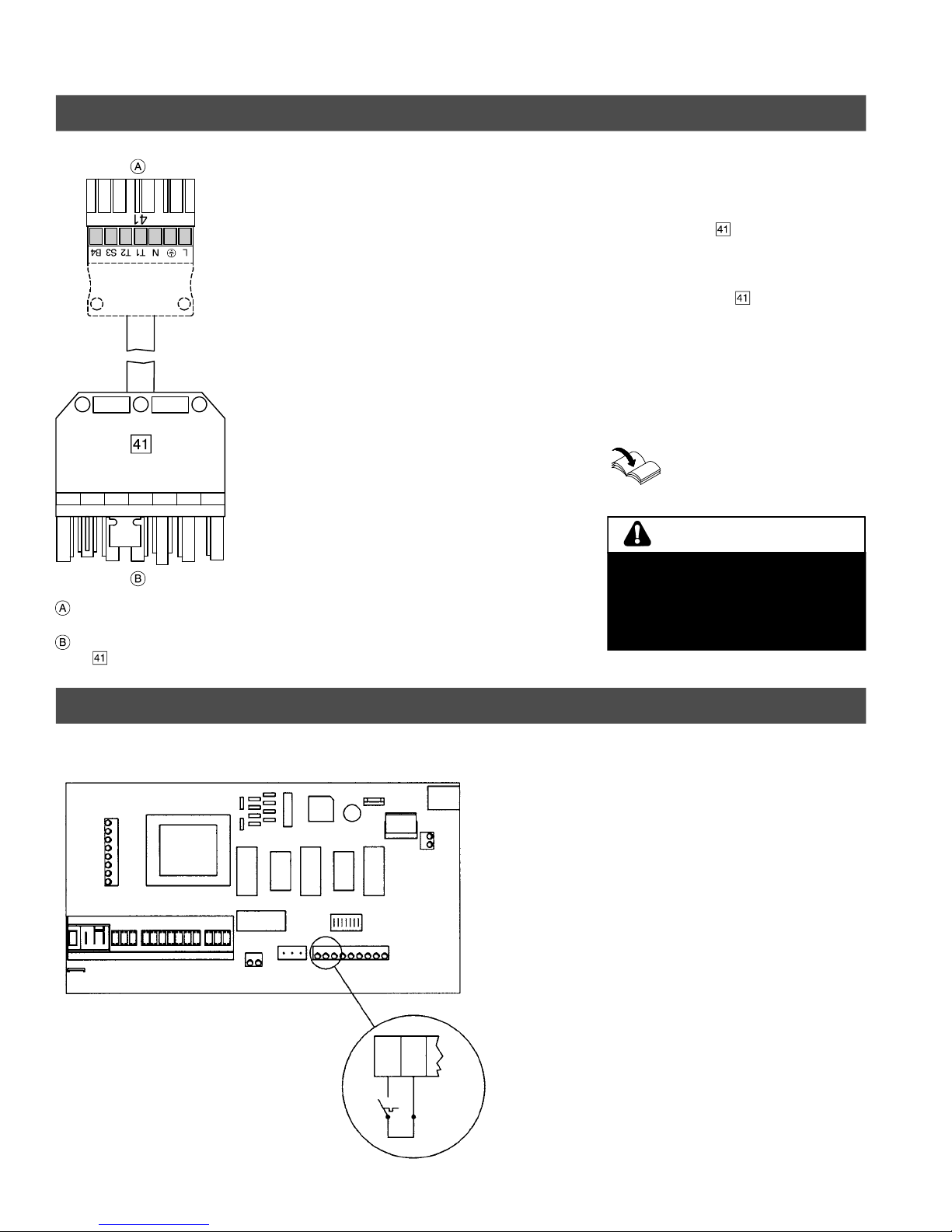
Burner Connection
The Vitotronic 100 is prewired with the
Viessmann quick-connect plug-in
system.
to control
(RAST-5 plug)
to burner or wall vent system
plug)
(
1. Connect the
main circuit board of the control
(see page 8)
2. Connect 7-pole
counter plug of the burner
or
if installing a wall vent system
(accessory), connect 7-pole plug to
counter plug of wall vent system.
Refer to technical instructions
of the burner and/or wall vent
system
RAST-5 plug to the
plug to the
WARNING
Do not connect the 41-plug from the
boiler control directly to the burner if
installing a wall vent system.
See technical instructions of the wall
Room Thermostat Connection
The main circuit board is pictured from the top.
A room thermostat or end-switches
from zone valves (in multi-zone
systems) can be connected to the room
thermostat connection. Connection
must be potential-free (”dry contact”).
1. Feed the cabling from the room
thermostat through rear top panel
wiring gate of the boiler. Use 2
conductor AWG 18 copper wire
only.
2. Slide cable into the strain relief and
secure with strain relief set screw.
3. Connect wires to main circuit board
as shown.
4. Set thermostat anticipator to 0.1 A.
10
5167 483 v1.4
Page 11
Pump Connection
Electrical Connections
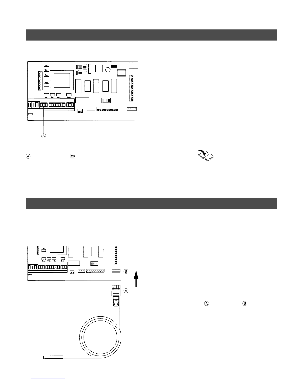
The main circuit board is pictured from the top.
The Vitotronic 100, KW10 incorporates
a 120 VAC pump output. The output is
activated when the boiler water
temperature exceeds the minimum
boiler temperature limit. The Pump
Junction Box (shipped with the boiler)
must be connected to the pump
connection.
The purpose of this output is to
minimize the possibility of flue gas
condensation with the following
boilers:
- Vitorond 200, VR2 Series
- Vitogas 050, RS Series
- Vitogas 100, GS1 Series
Pump connection
Boiler Sensor
See Installation Instructions of
the Pump Junction Box
(shipped with the boiler)
The Vitola 200 boiler has no low limit.
Do not use the pump connection with
the Vitola 200.
The main circuit board is pictured from the top.
Installation of boiler sensor
1. Insert the boiler sensor into the
boiler sensor well.
Do not kink any of the surrounding
capillaries.
2. Route cabling to boiler control
between enclosure panels and
insulation jacket.
Electrical connections
3. A plug is prewired to the boiler
sensor. Plug the “1/3” connector
into the socket of the main
circuit board.
5167 483 v1.4
11
Page 12
Electrical Connections
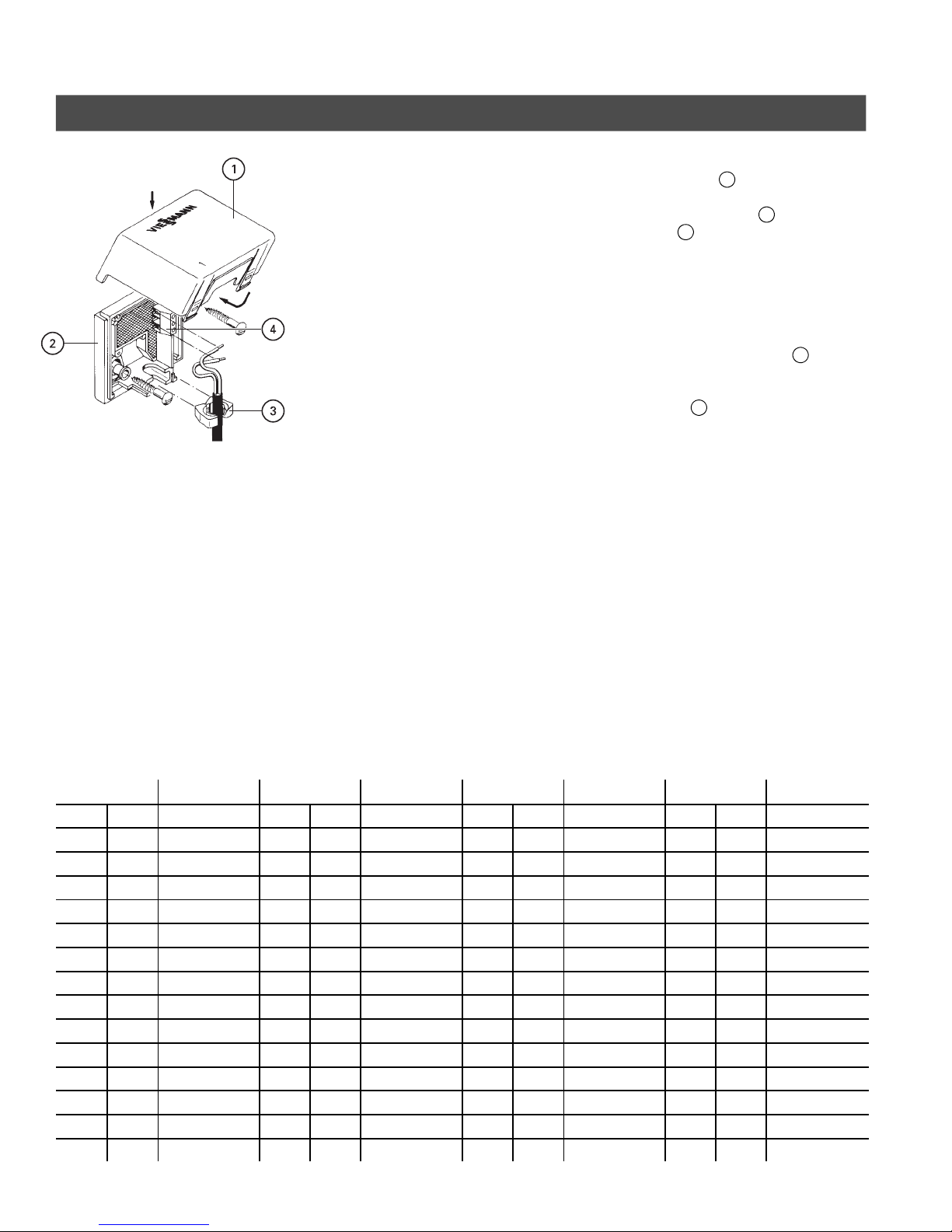
Installation of Outdoor Temperature Sensor
To mount outdoor temperature sensor,
experience has shown that the north or
north-west outside wall of the building
is the best location. If, however, the
boiler is intended to supply heat to the
south side of the building only (split
piping system), the sensor must be
mounted on the south side.
The sensor must be mounted so that
water cannot infiltrate the sensor
housing.
Care must be taken to install the
sensor where it will not be affected by
heat sources such as windows or
ventilation openings. The sensor should
be installed far enough above the
ground to prevent accidental damage
or tampering. Operating temperature
range is -60 to 160 °F / -50 to 70 °C.
Total cable length from boiler to sensor
should not exceed 1000 ft. / 300 m if
18 gage wire is used. This sensor cable
should not be placed in direct contact
with line voltage.
Installation
1.Remove cover1.
2.Mount housing base2(cable inlet
opening3to bottom).
The outdoor temperature sensor
must be surface-mounted on exterior
cladding - not encased in any way by
outside façade.
4
3.Affix wires to connectors
Wires are interchangeable.
4.Slip cover1in place and affix with
a snap.
Do not paint cover.
Electrical connections
5.Connect the other end of the
two-conductor cable to terminals “1”
and “2” of the “1 / 3” plug (boiler
sensor plug). Wires are
interchangeable.
.
In addition, the outdoor sensor must
not be covered with mortar, stucco,
paint or any form of coating or siding.
If the outside wall is finished after the
sensor is installed, the sensor should
be removed and placed on the finished
wall.
Temperature Resistance
ºF ºC Ω ºF ºC Ω ºF ºC Ω ºF ºC Ω
-50 -46 490813 20 -7 46218 90 32 7334 160 71 1689
-45 -43 405710 25 -4 39913 95 35 6532 165 74 1538
-40 -40 336606 30 -1 34558 100 38 5828 170 77 1403
-35 -37 280279 35 2 29996 105 41 5210 175 79 1281
-30 -34 234196 40 4 26099 110 43 4665 180 82 1172
-25 -32 196358 45 7 22763 115 46 4184 185 85 1073
-20 -29 165180 50 10 19900 120 49 3760 190 88 983
-15 -26 139402 55 13 17436 125 52 3383 195 91 903
-10 -23 118018 60 16 15311 130 54 3050 200 93 829
-5 -21 100221 65 18 13474 135 57 2754 205 96 763
0 -18 85362 70 21 11883 140 60 2490 210 99 703
5 -15 72918 75 24 10501 145 63 2255 215 102 648
10 -12 62465 80 27 9299 150 66 2045 220 104 598
15 -9 53658 85 29 8250 155 68 1857 225 107 553
Temperature Resistance Temperature Resistance Temperature Resistance
6.The outdoor sensor can be checked
by measuring resistance in respect to
current outdoor temperature.
Disconnect outdoor sensor from
control. Using an Ohmmeter,
measure resistance between the
sensor cable terminals. The expected
values are as follows:
5167 483 v1.4
12
Page 13
Fixed High Limit
highlimithigherthan167°F/75°C
.
Altering Settings
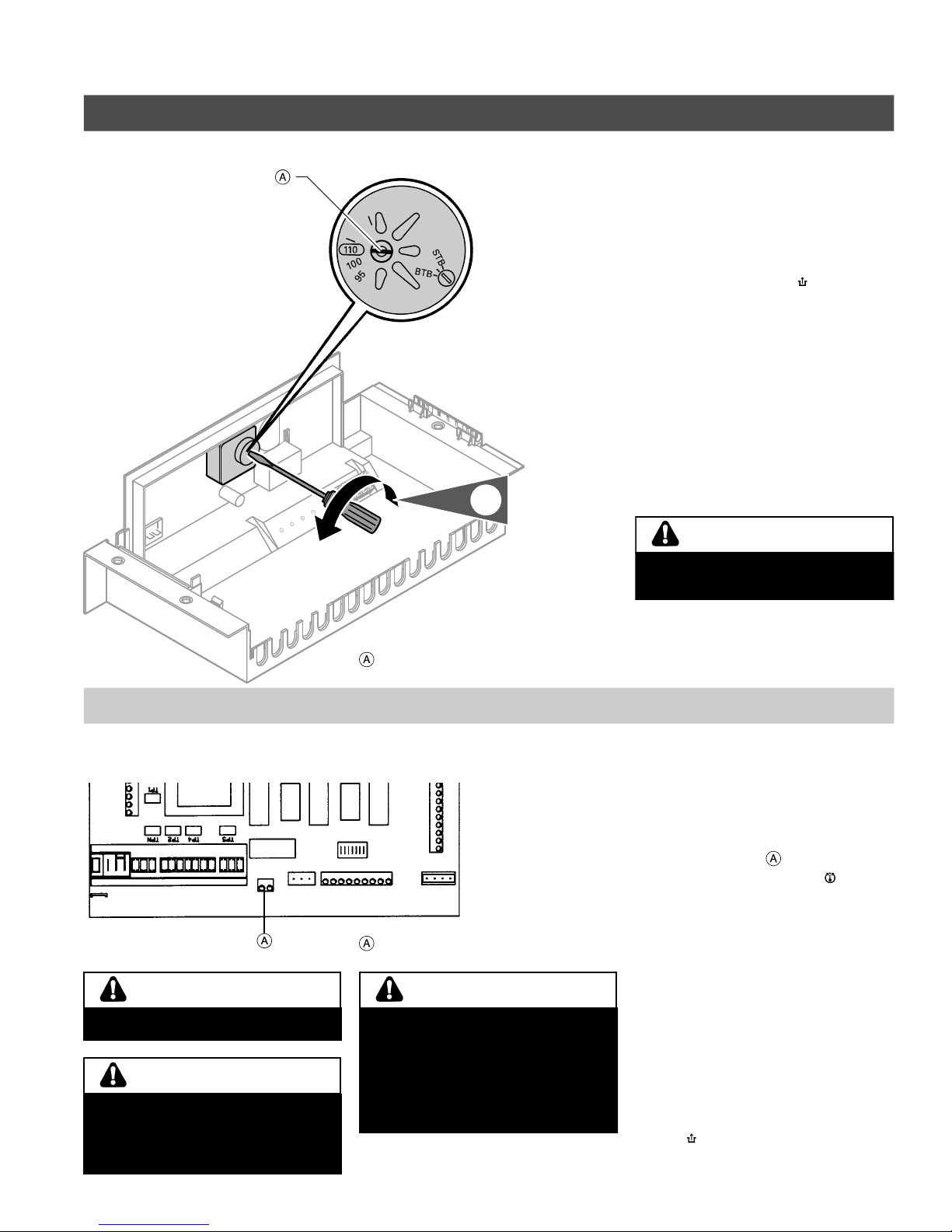
The default setting of the fixed high limit (FHL) is 230°F / 110°C.
The FHL deactivates the burner control
circuit if abnormally high temperatures
occur.
If tripped, it may be reset by pushing in
the pin, labelled with a “
ballpoint pen). If a “click” can be
heard, the limit was tripped.
Adjustment to 212°F / 100°C
1. Turn indicator screw at rear of FHL
to 212°F / 100°C position using a
flat-head screwdriver (readjustment
to previous position is not
possible).
2. Please complete Protocol on page
27.
1.
” (using a
Testing the FHL
CAUTION
A B Test connection is a 120 VAC
circuit!
CAUTION
Boiler and burner must be supervised
during entire procedure. Allow boiler
water temperature to cool down to
140°F / 60°C before activating any
attached heat distribution system.
5167 483 v1.4
If adjusting the fixed high limit to
212°F / 100°C, do not set adjustable
Slot screw
The main circuit board is pictured from the top.
A test can be performed to ensure
proper operation of the FHL:
→ Deactivate power to control.
→ Install a jumper between
→ The adjustable high limit “ ” is
→ Reactivate power to control.
FHL test connection, A B Test
CAUTION
Connected low temperature (floor
heating) systems, whether connected
with or without mixing valves, must be
deactivated during this procedure.
Attached DHW tanks must be isolated
and proper water expansion to the
expansion tank must be guaranteed
before performing this test.
→ The burner is activated until the
After deactivation of the FHL,
→ Deactivate power to control.
→ Remove jumper between
→ wait until boiler water temperature
→ Reactivate power to control.
CAUTION
terminal A and B .
disabled.
boiler water temperature reaches the
FHL temperature and the FHL
deactivates the burner.
terminals A and B.
has cooled 27 to 36°F / 15 to 20°C
below the FHL temperature and
reinitiate FHL by pushing in
“ ” pin.
the
13
Page 14
Altering Settings
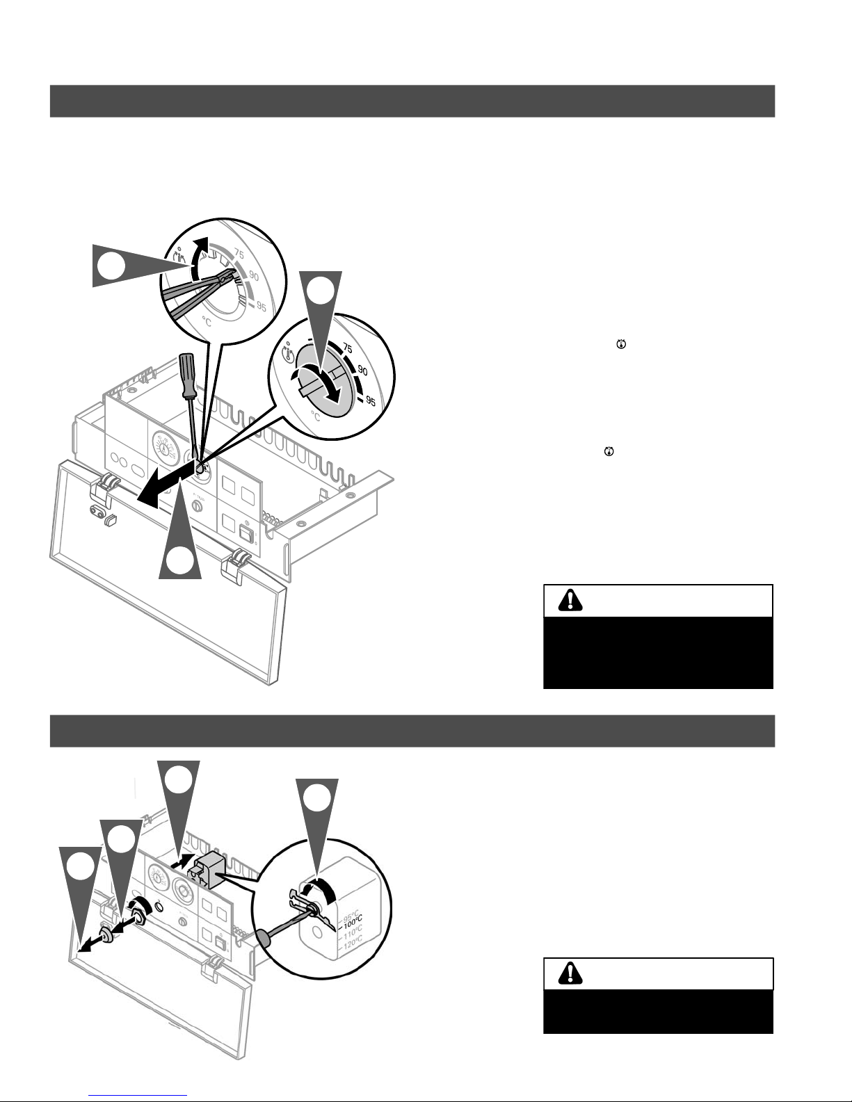
Adjustable High Limit
2.
The default setting of the adjustable high limit (AHL) is 167°F / 75°C.
The AHL must not be set higher than 167°F / 75°C if the FHL is set to
212°F / 100°C.
The AHL sets the maximum boiler
water temperature. It deactivates the
burner control circuit when the desired
temperature is reached. The AHL
3.
resets automatically on a decrease in
boiler temperature.
Adjustment to 189°F / 87°C
1. Remove
screwdriver.
2. Using needle-nose pliers, break off
tabs enabling dial to rotate right to
desired maximum temperature.
3. Install dial in such a way that its
mark is situated in the desired
temperature range.
dial using a flat-head
1.
Changing the setting of the high limit safety cut-out
3.
4.
2.
1.
4. Please complete Protocol on page
27.
WARNING
The allowable temperature of domestic
hot water, as specified by regional
standards, must not be exceeded when
operating an indirect-fired DHW tank.
Install additional safety devices!
Adjustment to 100°C for side scales
1. Remove reset button cover “E”.
2. Remove the nut.
3. Remove the high limit safety
cut-out.
4. Turn the screw until the indicator
points to 100°C.
14
CAUTION
If adjusted to 212° F/100° C do not
set the adjustable high limit above
167°F/75°C.
5167 483 v1.4
Page 15
Dip Switch Settings
alterdipswitchsettings.
CAUTION
Ensure power switch on boiler control
is deactivated before attempting to
Altering Settings
The “sequence of operation” of the Vitotronic 100, Model KW10 can be
customized depending upon the boiler it is installed with, or the characteristics of
the heating system itself.
Dip switch settings are to be altered by a qualified heating contractor only. See
Overview on page 8 for dip switch location.
Default
Setting
S1.1 - OFF Do not change
S1.2 - OFF Staging and thermostat:
S1.3 - ON Do not change
S1.4 - ON For single- and two-stage boilers:
S1.5 - ON For two-stage boilers:
Operation Possible
for two-stage boilers where control of
both stages is needed
with minimum boiler temperature
protection
with minimum boiler temperature
protection and DHW production (where
DHW pump module is used), using first
and second stage
*1
Change
from OFF
setting
ON Staging and thermostat:
from ON
setting
OFF For single- and two-stage boilers:
OFF For two-stage boilers:
Operation
for two-stage boilers where control of
both stages is not needed
Both stages are activated simultaneously
for space heating and for minimum boiler
temperature protection
without minimum boiler temperature
protection
with minimum boiler temperature
protection and DHW production (where
DHW pump module is used), using first
stage only
*1
S1.6 - OFF For domestic hot water production and
S1.7 Not used
*1
See DHW pump module Installation Instructions for jumper J1position.
5167 483 v1.4
space heating with a DHW Pump Module:
space heating pump and DHW pump are
disabled when boiler water temperature is
below the minimum value
ON For domestic hot water production and
space heating with a DHW Pump Module:
space heating pump and DHW pump are
enabled when boiler water temperature is
below the minimum value
15
Page 16
Altering Settings
Altering the Indoor/Outdoor Control Settings
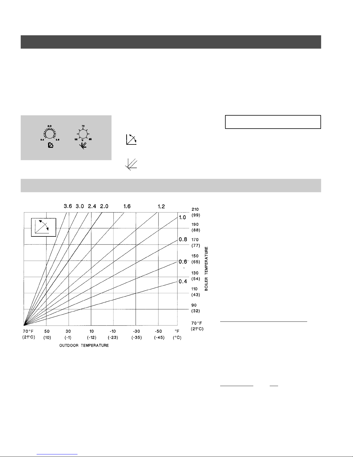
The adjustable high limit determines the maximum available boiler (supply)
temperature. Therefore, it functions as a high limit.
The room thermostat (if used) enables and disables the outdoor reset processor in
order to add indoor control (fine tuning) to the outdoor reset function.
The curve for the outdoor reset function can be adjusted by opening the front
flip-down cover.
Factory settings
Heating curve slope
“ “
selection = 1.2
Warm weather shut-down (WWSD)
“ “
selection = 70 °F / 21 °C
Slope adjustment
IMPORTANT
If there is no call for heat from the room
thermostat, the burner will not be
activated, even if the heating curve
setting calls for a higher temperature.
As outdoor temperatures drop, heat
losses from a space become greater and
the heating system supply water
temperature must be raised to maintain a
constant room temperature. The heating
curve value describes how many degrees
the supply water temperature is raised for
a one degree drop in outdoor
temperature. The supply temperature
starts to increase when the outdoor
temperature falls below the warm
weather shut-down (WWSD) setting.
To calculate the correct setting for the
heating curve, use the following formula:
heating curve slope =
design supply temp. - WWSD temp.
WWSD temp. - design outdoor temp.
Example:
design outdoor temp.: 5 ˚F / -15 ˚C
WWSD temperature: 70 ˚F / 21 ˚C
design supply temp.: 160 ˚F / 71 ˚C
heating curve slope =
16
160 ˚F - 70 ˚F 90 ˚F
= = 1.4
70 ˚F - 5 ˚F 65 ˚F
For further assistance, please see section
entitled “Helpful hints.”
5167 483 v1.4
Page 17
Altering the Indoor/Outdoor Control Settings (Continued)
Warm weather shut-down adjustment
Altering Settings
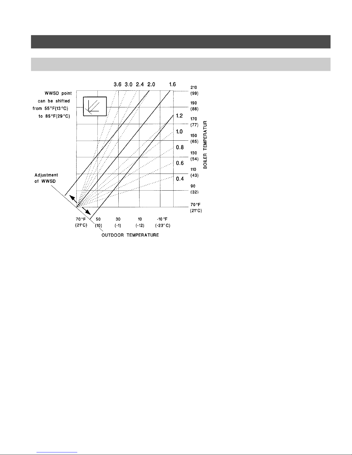
The reset function starts at the warm
weather shut-down (WWSD) point and
supplies increasingly more heat to a
building to make up for the greater heat
loss as outdoor temperatures get colder.
When the outdoor temperature rises
above the setting of the WWSD dial, no
more heat is required by the control, and
the boiler will be shut down. The WWSD
dial setting shifts the heating curve up or
down in parallel, increasing or decreasing
the system supply water temperature
(and consequently, the indoor air
temperature) at all outdoor temperatures.
If the indoor air temperature is too hot or
too cold at all outdoor temperatures, the
WWSD setting is probably incorrect and
should be checked and adjusted to suit
your requirements.
For further assistance, please see section
entitled “Helpful hints” in the Operating
Instructions and User’s Information
Manual.
5167 483 v1.4
17
Page 18

Appendix / Start-up
After Installation ...
Checklist
Please verify the following points
(check with a pen) and take corrective
actions as necessary:
Service Binder
j Have all limit capillaries and sensors
been completely inserted into the
boiler 5-point sensor wells?
j Have all electrical connections been
made as discussed in the previous
section?
j Did all plug-in connectors engage
with a “click” ?
j Have the settings of both the fixed
high limit and the adjustable high
limit been checked and altered as
necessary?
j Has the Pump Junction Box been
wired correctly (if applicable)?
1. File all technical documentation into
the Service Binder.
2. Install a protective service box
(optional equipment) near the boiler
and store the Service Binder in this
location.
Start-up Instructions
1. Check all connections
Based upon the Section entitled “Overview” on page 8, ensure all electrical
connections have been made according to the diagram.
2. Ensure settings on fixed high limit and adjustable high limit are correct
See pages 13 and 14.
3. Ensure correct operational settings on control are set
Read Operating Instructions and User’s Information Manual of Vitotronic.
The installer on the system is also responsible to ensure the system
operator/ultimate owner is made familiar with the system functioning, its
activation, and its shut-down.
5167 483 v1.4
18
Page 19
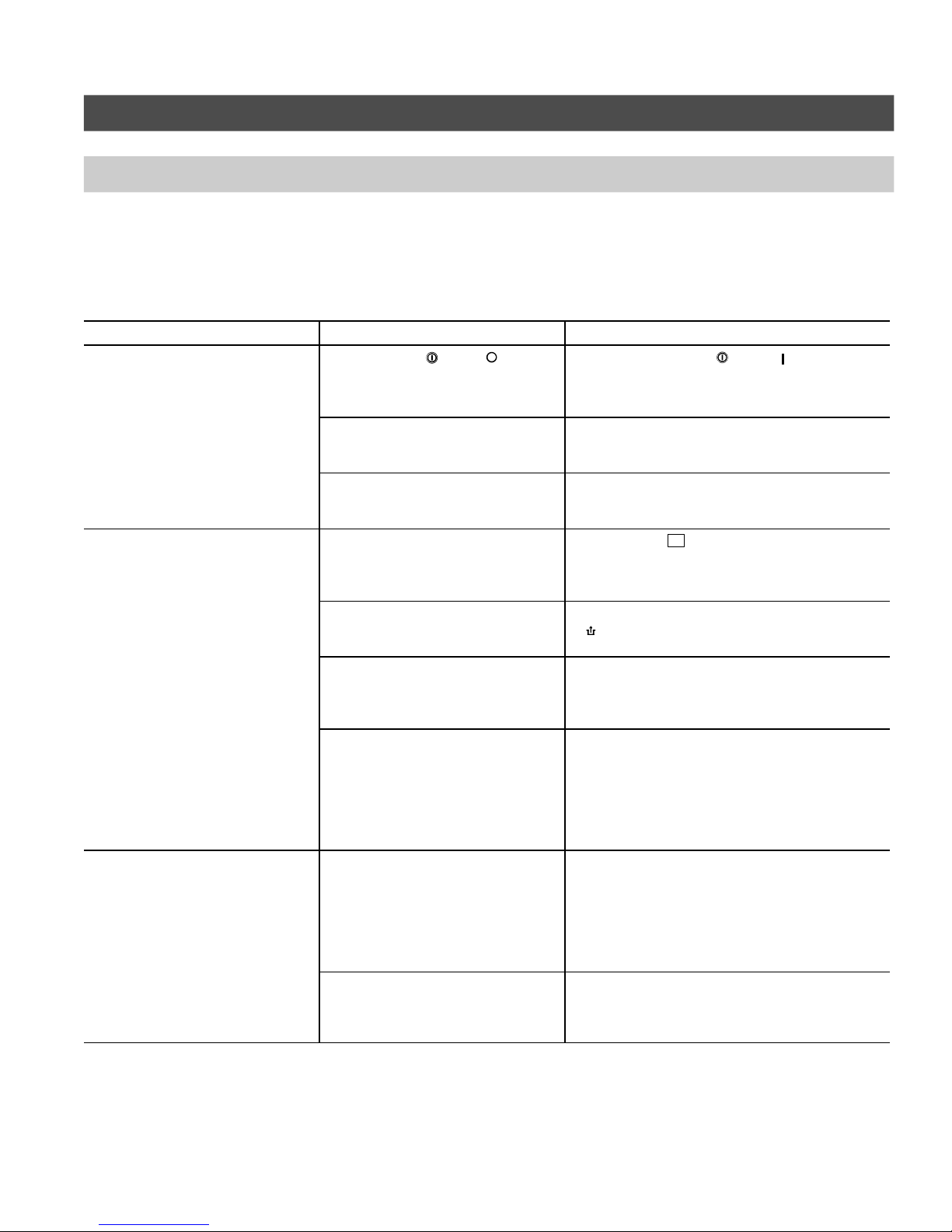
Diagnostics (for qualified service personnel only)
Failure, Cause, Correction
j Are all controls operating properly
(i.e. thermostats, low water
cut-off, etc.)?
j Are all wire connections tight and
secure?
Failure Cause Correction
Heating system does not activate
(GREEN power LED is not
illuminated)
Burner does not activate, or
activates intermittently
(RED fault LED flashes)
Power switch “ “ is in “ “
position
Main power to boiler control and
heating system has not been
activated
Fuse on Vitotronic boiler control
has deactivated heating system
Burner is not electrically connected
Fixed high limit (FHL) tripped
No fuel
Control calls for heat but burner
does not respond
*1
*1
Ensure power switch “ “ is in “ “ position.
Activate main power; ensure 120 VAC is
supplied to control (receptacle).
Replace fuse in control with same type and
rating
(F1: T 6.3 A / 250 V, slow blow).
Ensure 7-pole plug-in connection
to burner and/or power venter is/are
made.
Reset FHL by pushing in the pin, labelled with a
“ “ (using a ballpoint pen).
If a “click” can be heard, the limit was tripped.
with oil: Ensure sufficient supply of oil
with gas: Open main gas supply valve
or
contact your local gas utility
Attempt to reset burner using reset
button on the burner
(underneath burner hood).
Troubleshooting
41
Burner does not activate
*1
Red LED does not flash when Honeywell S8600 ignition control module is used with boiler.
5167 483 v1.4
Control calls for heat but burner
does not respond
Other accessory defect
Service burner if necessary.
Refer to troubleshooting section in
burner manual.
Power venter has to have separate
120 VAC power supply to motor (see
power venter instructions).
Refer to troubleshooting section in
power venter manual. Air proving
switch, blower wheel or timer/relay
inside power vent may be defective.
Ensure proper operation of all accessories;
replace if necessary.
Refer to technical literature supplied with
accessories.
19
Page 20

Troubleshooting
Diagnostics (for qualified service personnel only)
Electrical connections and sequence of operation
The plug of the Vitotronic 100, Model KW10 boiler control supplies power to
the RAST-5 connection on the main circuit board. This plug connector has L1, G
and N markings on its terminals.
If the power switch is closed, power is supplied to the F1 fuse (6.3 A). This fuse
is accessible from the front of the control. The output of the fuse is connected to
the fixed high limit (FHL), the pump aquastat (PA), the primary side of the
transformer (TR), and test point 1 . When the contacts of the FHL are closed,
terminal X1.5 and test point 2 will both have 120 VAC present. Power flow will
continue to the L1 terminal of the
If the burner counter plug is connected, voltage will return back to the control
at terminal T1 on the RAST-5 plug. As the power flow continues in the control,
voltage will be present at test point 3 and X1.6. If the adjustable high limit (AHL)
is closed, and the boiler water temperature is below the AHL setting, 120 VAC
will be present on X1.7 and test point 4.
On a call for heat or for domestic hot water production (with DHW Pump Module,
Accessory), contact 1K1 will be closed and 120 VAC will be present on terminal
T2 of the RAST-5 burner plug. Test point 5 will also have 120 VAC present at
this time. The power flow will continue to the burner. The burner will operate until
the thermostat ends the call for heat.
connection on the RAST-5 terminal rail.
The space heating circuit switch is only operational if a DHW Pump Module
(Accessory) is installed.
20
5167 483 v1.4
Page 21
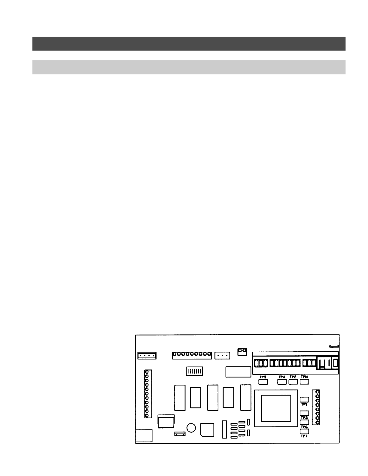
Diagnostics (for qualified service personnel only)
Backofcontrol
Electrical connections and sequence of operation
Using a volt-ohm meter, place one probe onto neutral test point terminal (TPN).
Use the remaining probe to touch the individual test points to diagnose the
problem. Follow the steps below through the individual test points.
Test point 1
Is 120 VAC present?
No Check main 6.3A fuse and replace as necessary. Retest.
Yes Continue with Test point 2.
Test point 2
Is 120 VAC present?
No FHL has tripped. Reset and ensure pump(s) are operating.
Yes Continue with Test point 3.
Test point 3
Is 120 VAC present?
No Power flow is not returning from burner. Check burner plug.
Yes Continue with Test point 4.
Troubleshooting
Test point 4
Is 120 VAC present?
No AHL has tripped. Allow boiler to cool and restart.
Yes Continue with Test point 5.
Test point 5
Is 120 VAC present?
No Contact 1K1 possible not closed.
Test burner operation using FHL test.
Check room thermostat circuit.
Yes Burner operation is required at this point.
Service burner.
Top view of main circuit board
5167 483 v1.4
Front of control
21
Page 22
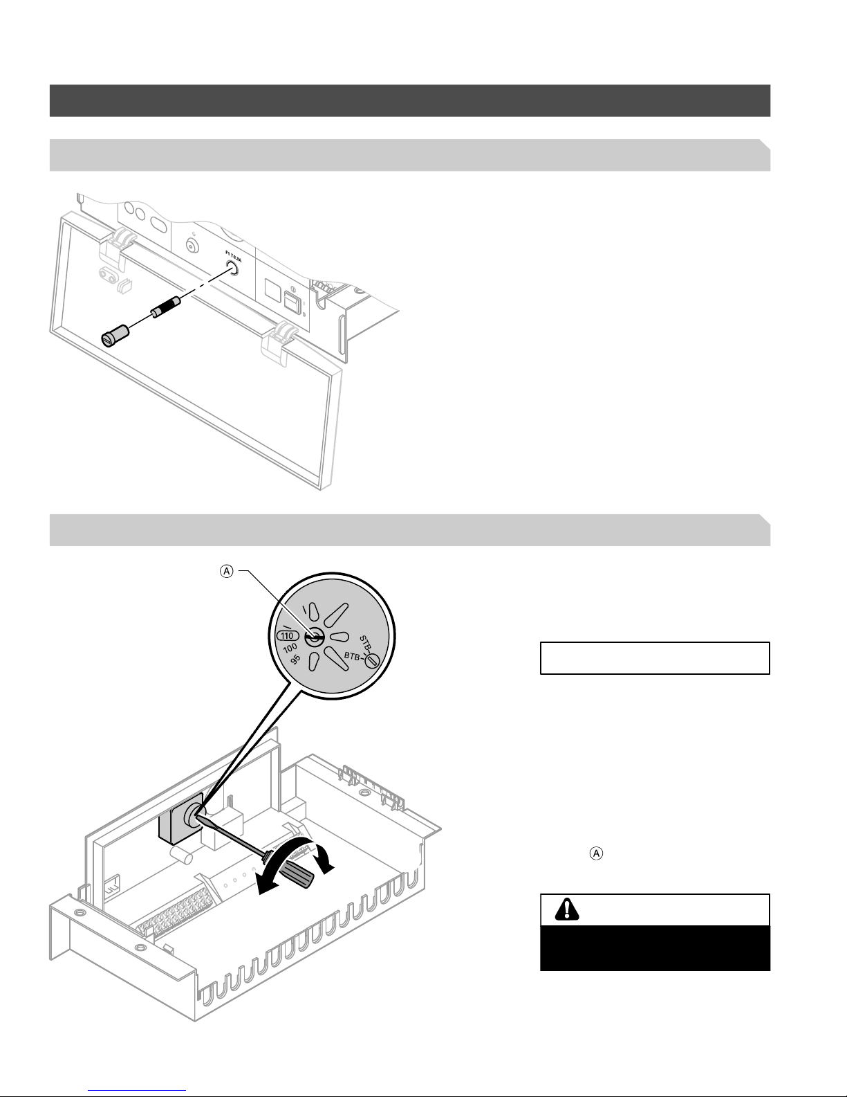
Additional Information
Replacement Components (for qualified service personnel only)
Fuse, Part No. 7815 580
F1: T 6.3 A / 250 V, slow blow
for control operation
Fixed high limit, Part No. 7819 411
H Electro-mechanical temperature limit
with liquid filled capillary
H Safety feature: if capillary is not
liquid tight (leaks), switch deactivates
IMPORTANT
Due to the expansion characteristics of
the liquid contained in the capillary, the
switch also deactivates (opens) at 14°F /
-10°C thereby shutting down the heating
system.
H Sets a maximum limit for boiler water
temperature whereafter the switch
deactivates and locks
(factory setting 230°F / 110°C)
HHHH Adjustable to 212°F / 100°C via slot
screw on rear side (readjustment
to previous position is not possible)
WARNING
If adjusting to 212°F / 100°C, AHL
must not be set higher than 167°F /
75°C.
22
5167 483 v1.4
Page 23
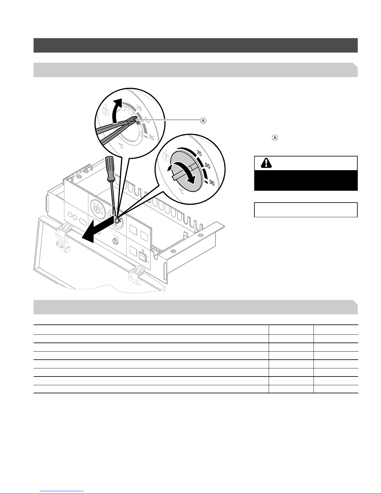
Replacement Components (for qualified service personnel only)
Adjustable high limit, Part No. 7819 316
Additional Information
H Electro-mechanical temperature limit
with liquid filled capillary
H Controls maximum boiler water
temperature
(Factory setting 167°F / 75°C)
H Adjustable to 189, 203 and 212°F /
87, 95 and 100°C by breaking off
tabs
desired maximum temperature.
enabling dial to rotate right to
WARNING
AHL setting must be at least 36°F /
20°C higher than DHW tank
temperature.
IMPORTANT
The AHL must not be set higher than
167°F / 75°C if the FHL is set to
212°F / 100°C.
Other replacement components (not shown)
Description Quantity Part No.
Temperature gage, °F 1 7334 598
Temperature gage, °C 1 7334 599
Temperature gage, °C / °F 1 9543 566
Vitotronic 100 main circuit board, KW10 1 9544 170
LED circuit board 1
Indoor/outdoor control 1
Pump aquastat 1 9525 828
5167 483 v1.4
23
Page 24

Additional Information
Boiler Protection
Boiler Protection
Minimum boiler temperature protection has been selected for all Vitotronic
controls. It is the responsibility of the installer to determine the requirements of
the boiler for each specific installation. The minimum boiler temperature function
may be disabled; to do so, refer to table in subsection “Minimum Boiler
Temperature Setting”.
The boiler construction determines the necessity of a minimum boiler temperature
protection function.
Minimum boiler protection is the result of two separate functions of the
Vitotronic, KW10 control:
– activation of the burner
– deactivation of the space heating pump.
The Vitotronic 100, KW10 control uses a pump aquastat (PA) in conjunction with
an Outdoor Reset Control (ORC) to maintain a minimum boiler temperature. The
aquastat uses a probe-type mechanical limit which monitors the boiler water
temperature. When the boiler water temperature drops below the setpoint of the
pump aquastat, the burner activates and the space heating pump is deactivated.
The ORC also controls the burner by sensing the boiler temperature through the
electronic boiler sensor. When the boiler water temperature drops below the
selected setpoint temperature, the ORC will activate the burner and deactivate the
space heating pump. This only occurs when the room thermostat initiates a call for
heat. The room thermostat may be jumpered to provide a constant call for heat.
The ORC will also deactivate the space heating pump when connected to the
DHW pump module.
The space heating pump may be connected to the Vitotronic 100, KW10 control
in one of two ways:
– using a boiler-mounted pump junction box
– using a DHW pump module (accessory).
The presence of the boiler-mounted pump junction box is determined by the
boiler-specific construction.
When the space heating pump is connected to the boiler-mounted pump junction
box, the pump is deactivated when the boiler water temperature drops below the
pump aquastat setpoint. If continuous operation of the space heating pump is
required, a separate power supply connection is needed. When connecting the
pump to a direct power supply, the use of a pump on/off switch is recommended.
When the space heating pump is connected to the boiler via the DHW pump
module, pump operation is similar to that with pump connection via the pump
junction box. When the boiler temperature drops below the aquastat setpoint, the
space heating pump is switched off. If a DHW pump is connected, it also is
switched off. To modify pump operation, refer to table in subsection “Minimum
Boiler Temperature Setting”.
Burner activation is similar to that of the pump control. When the boiler
temperature drops below the pump aquastat setpoint, the burner is activated. The
pump aquastat controls the burner operation when the boiler temperature is below
the aquastat setpoint. If the ORC detects that the boiler water temperature has
dropped below the setpoint, the burner will be activated by the ORC control.
24
5167 483 v1.4
Page 25

Boiler Protection (continued)
Additional Information
There is a 7-pole DIP switch located on the motherboard of the control and a
5-pole DIP switch on the outdoor reset control.
Operation of the PA or the burner can be modified by changing the DIP switch
settings. Refer to the table in subsection “Minimum Boiler Temperature Settings”
for the Vitotronic 100, KW10 control.
The ORC can maintain two alternate minimum boiler water temperatures.
H DIP switch S2.2 maintains the boiler temperature at 100
H deactivate DIP switch S2.2 and activate DIP switch S2.3 for a new minimum
boiler temperature of 120°F / 49°C
H deactivate DIP switches S2.2 and S2.3 and activate DIP switch S2.4 for a new
minimum boiler temperature of 140°F / 60°C
The S2.2, S2.3 and S2.4 DIP switches are found on the position switch assembly
on the outdoor reset board.
When all three DIP switches are kept deactivated or in the downwards position,
the ORC will not maintain a minimum boiler water temperature and the space
heating pump will not deactivate on low boiler temperatures. These settings must
be used in conjunction with the S1 DIP switch settings to fully disable minimum
boiler temperature protection.
°F / 38°C
Minimum boiler temperature setting
Boiler control without DHW pump module
Minimum
temperature setpoint
PA 86-95 °F / 30-35 °C
ORC 100 °F / 38 °C
PA 86-95 °F / 30-35 °C
No ORC minimum
temperature
No PA minimum
temperature
ORC 100 °F / 38 °C
No PA minimum
temperature
No ORC minimum
temperature
Vitotronic DIP switch
S1.4 position
ON ON Burner enabled when
ON OFF Burner enabled when
OFF ON Burner enabled when
OFF OFF Burner NOT enabled
Minimum temperature protection can be deactivated by changing the position of
the DIP switch S1.4 (downwards movement of the DIP switch). Please refer to
table in subsection “Minimum Boiler Temperature Setting”.
ORC minimum temperature DIP switch S2.2
Burner operation Boiler pump connected to
boiler below ORC set-
*1
ting
boiler temperature below
PA setting
boiler temperature below
ORC setting
No minimum boiler
temperature maintained
*1
boiler junction box
Pump off when below PA
setting
Pump off when below PA
setting
Pump off when below PA
setting
Pump off when below PA
setting
5167 483 v1.4
25
Page 26

Additional Information
Boiler Protection (continued)
Minimum boiler temperature setting (continued)
Boiler control with DHW pump module
Minimum
temperature setpoint
PA 86-95 °F / 30-35 °C
ORC 100 °F / 38 °C
PA 86-95 °F / 30-35 °C
No ORC minimum
temperature
No PA minimum
temperature
ORC 100 °F / 38 °C
Vitotronic DIP switch
S1.4 position
ON On Burner enabled when
ON OFF Burner enabled when
OFF ON Burner enabled when
ORC minimum temperature DIP switch S2.2
Burner operation Boiler pump connected to
DHW pump module
Pump off when boiler
boiler temperature below
ORC setting
*1
temperature below PA
*2
setting
Pump off when boiler
boiler temperature below
PA setting
temperature below PA
*2
setting
Pump off when boiler
boiler temperature below
ORC setting
*1
temperature below PA
*2
setting
No PA minimum
temperature
OFF OFF Burner NOT enabled
No minimum boiler temperature maintained
Pump off when boiler
temperature below PA
*2
setting
No ORC minimum
temperature
PA Pump Aquastat
ORC Outdoor Reset Control
*1
The minimum boiler water temperature, with the outdoor reset control, will only be activated when the room thermostat connection is
closed or a jumper is used.
*2
When the Vitotronic 100, KW10 control is used with DHW Pump Module, the factory default setting will allow the space heating pump
and the DHW pump to turn off below minimum boiler water temperature. This function can be disabled by changing the S1.6 DIP switch
setting from the OFF position to the ON position (upwards movement of DIP switch). The Outdoor Reset Control in this table is referred to
as ORC and the Pump Aquastat is referred to as PA.
The Vitola 200 does not have a boiler-mounted pump junction box.
26
Page 27
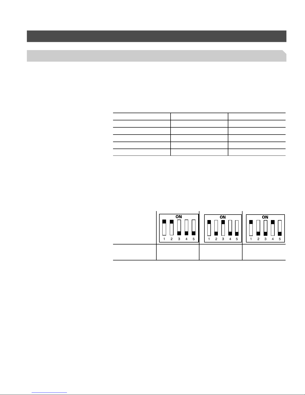
Boiler Protection (continued)
Minimum temperature adjustment for Vitotronic KW10
The minimum boiler water temperature setpoint can be adjusted to a higher boiler
water temperature. This may be useful in applications using high temperature
heating circuits.
To determine whether an increase in minimum boiler water temperature setpoint is
recommended for your application, read the following information.
Minimum boiler water temperature
Boiler model Fuel type (by boiler) Minimum boiler temperature
Vitola 200 Oil/Gas No minimum
Vitorond 200 Oil 104 ºF/40 ºC
Vitogas 050, RS Gas 120 ºF/49 ºC
Vitogas 100, GS1 Gas 104 ºF/40 ºC
Vitogas 100, GS10 Gas 120 ºF/49 ºC
Additional Information
To adjust the minimum temperature for the Vitotronic 100, KW10 control, select
an alternate DIP switch setting. The table below outlines the three DIP switch
settings for the three various temperatures. Select the temperature which best
suits your application.
Note: Select only one of the three DIP switch positions that effect minimum
temperature.
DIP switch setting
on outdoor reset
board
Minimum boiler
temperature setpoint
100 °F / 38 °C 120 °F / 49 °C 140 °F / 60 °C
Do not change the pump aquastat setting for minimum boiler water temperature.
Only change the minimum boiler water temperature by adjusting the DIP switch
settings.
27
Page 28
Additional Information
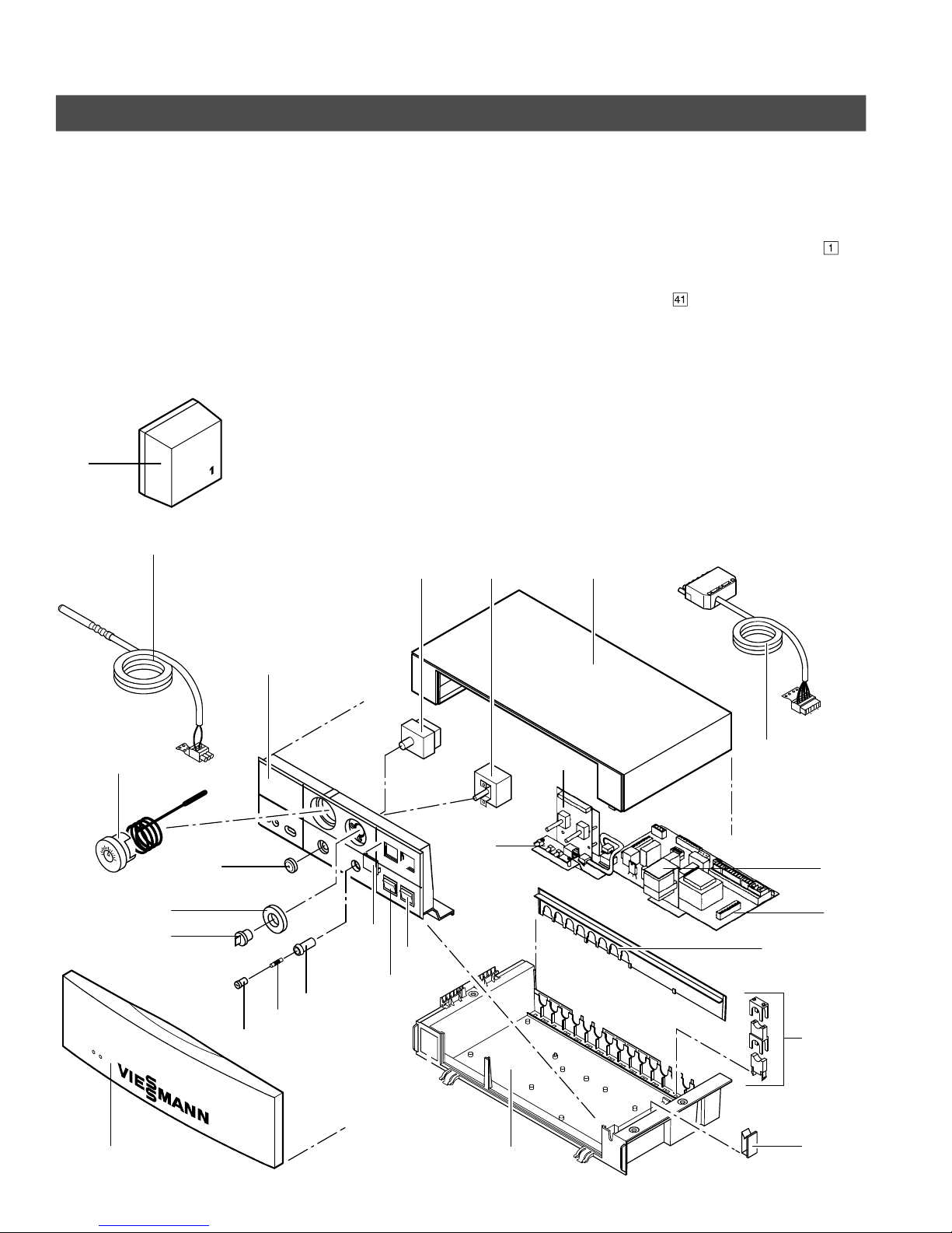
Parts List
Ordering Replacement Parts:
Please provide control Model No.,
Serial Number from rating plate, as well
as the position number of the part (see
Parts List) when ordering replacement
parts. Order replacement components
from your Viessmann distributor.
040
042
Part
001 Cable clip
004 Adjustable high limit dial
005 Fixed high limit cover
007 Flip-down cover
010 Control housing cover, top
011 Control housing, front
016 Control housing, bottom
017 Control housing, rear
018 Temperature gage
019 Switch knockout
023 Fuse holder
024 Fuse holder cover
030 Fixed high limit
031 Adjustable high limit
032 Pump aquastat
033 AHL knob
030 010
031
035 Space heating circuit switch
036 Power switch
037 Main circuit board
038 LED circuit board
039 Indoor/outdoor control
040 Outdoor temperature sensor
042 Boiler sensor
065 Burner cable with
plug connector
(shipped with burner or boiler)
091 Fuse
T 6.3 A / 250 V, slow blow
098 Strain relief fittings package
Parts not illustrated
080 Installation, Start-up
and Service Instructions
085 Operating Instructions
and User’s Information Manual
099 Other fittings package
018
004
033
005
024
011
091
023
019
035
036
038
039
065
032
037
017
098
007
28
016
001
5167 483 v1.4
Page 29
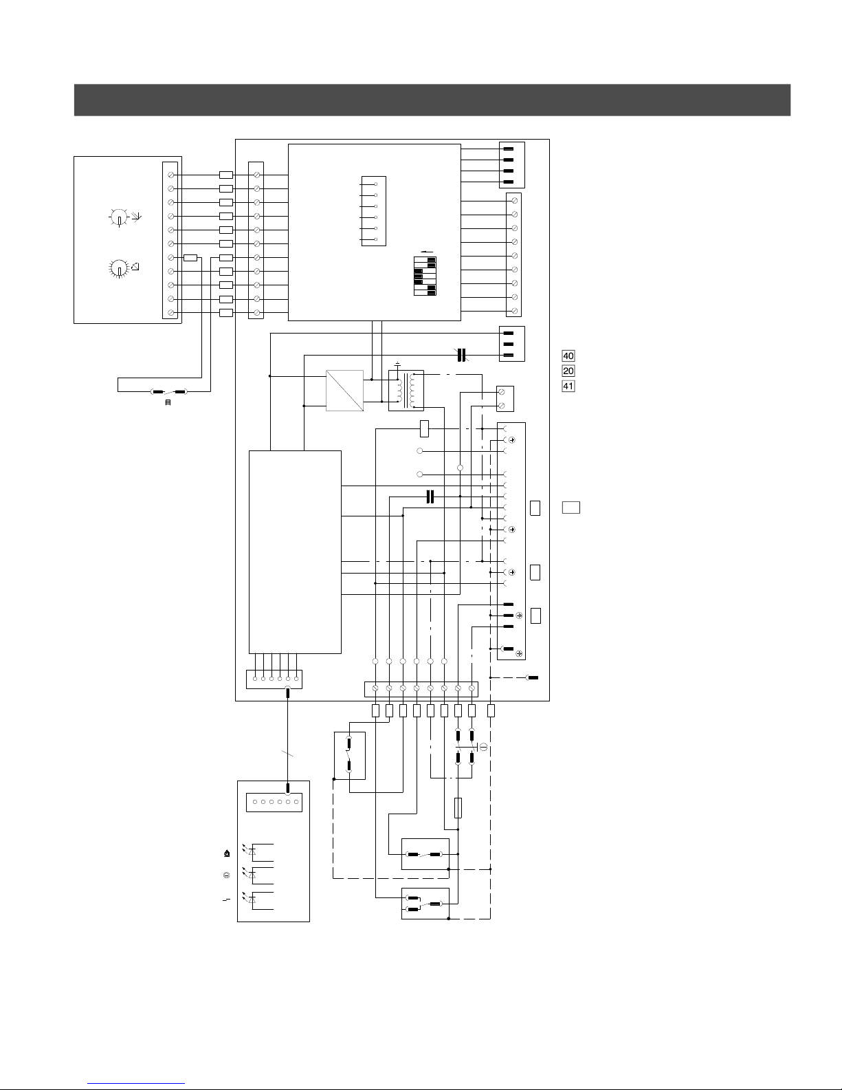
Wiring Diagram
5
1
6
7
4
8
3
v
1
.
4
F
o
85
55
0.4
3.6
2.0 70
PCB3 VBR1002
BN
1 2 3 4 5 6 7 8 9 10 11
S3
Additional Information
PCB1 Mother circuit board
3
GY
GN
984 65 7 10 11
VT
OG
RD
BN
BN
BK
321
WH
YE
BU
+
LED CONTROL
1
2
J
2
1
J
X4
345
3
24VAC CIRCUIT
DC
24VDC
-
6
6
AHL
654
6
4 5
1 2 3
AC
TP6
TP4
8
7
X1
BNGYVTOGBURDBK
2/C*
1
PORT
COMMUNICATION
ON
76
1 32 54
S1
1K2
K4
ALT
TP5
1K1
TPN
TP1
1
2
WH
F
6.3A
TP3
6
X6
TP2
543
2 4
1
1 2 3 4 5 6 7 8 9
X2
2 3
1
ABTEST
N
L1
B4
T1 T2 S3
N
L1
N
L1
L1
N
GN
S2
PCB2 Diode circuit board
1/3
PCB3 Outdoor reset control
F Fuse
K1, K2,
K4 Relays
S1 DIP switch
S2 Power switch
S3 Space heating switch
AHL Adjustable high limit
FHL Fixed high limit
PA Pump aquastat
120 VAC Connections
191
Power supply (120 V, 60 Hz)
Heating circuit pump
Burner connection
ALT Alternative input/output
TEST FHL test terminal
ALT
24 VAC Connections
X2 Room thermostat connection or
DHW pump module connection
X4 Outdoor reset control connection
191
41
2nd stage cable connection
1/3 Sensors connection
This wiring diagram applies only to
installations where Viessmann products
20
are used.
Technical information subject to
40
change without notice.
Wire color code
G
BK black
BN brown
PCB1
RD red
OG orange
YE yellow
GN green
BU blue
VT violet (purple)
GY gray
WH white
12/2*
FHL
4
PCB2
2
11/1*
PA
1
*The terminal designation shown will
depend on the switch model used.
29
Page 30

Additional Information
Technical Data
Power: 120 VAC
1 Phase
60 Hz
15 A pre-fuse
Burner switching capacity:
120 VAC
2.5 FLA
Room thermostat:
24 VAC
Anticipator setting:
0.1 A
Fixed high limit:
230°F / 110°C max.
(fixed)
Adjustable high limit:
167 to 239°F max.
75 to 115°C max.
(adjustable)
Pump output:
120 VAC
1 Phase
60 Hz
3 FLA
Outdoor temperature sensor:
10 kilo Ohms at
77°F / 25°C
max. wire length
up to 1000 ft. / 300 m
Allowable ambient temperature:
H operation: 32 to 104°F
0 to 40°C
H storage and transport:
-4 to 149°F
-20 to 65°C
Protocol
Please indicate settings
which have been altered ...
Factory default settings Altered settings
H Fixed high limit “ ” set to 230°F / 110°C j Altered to 212°F / 100°C
H Adjustable high limit “ ” set to 167°F / 75°C j Altered to 189°F / 87°C
30
5167 483 v1.4
Page 31

31
5167 483 v1.4
Page 32

Quick Reference
5
1
6
7
4
8
3
v
1
.
4
°C °F
-40 -40
-35 -31
-25 -13
-20 -4
-18 0
-16 +3
-14 +7
-12 +10
-10 +14
-9 +16
-8 +18
-7 +19
-6 +21
-5 +23
-4 +25
-3 +27
-2 +28
-1 +30
0 +32
+1 +34
+2 +36
+3 +37
+4 +39
+5 +41
+6 +43
+7 +45
+8 +46
+9 +48
+10 +50
+12 +54
+14 +57
+16 +61
+18 +64
+20 +68
+25 +77
+30 +86
+35 +95
+40 +104
+50 +122
+60 +140
+70 +158
+80 +176
+90 +194
+100 +212
+110 +230
Printed on environmentally friendly
(recycled and recyclable) paper.
Technical information subject to change without notice.
Viessmann Manufacturing Company (U.S.) Inc.
45 Access Road
Warwick, Rhode Island • 02886 • USA
Tel. (401) 732-0667 • Fax (401) 732-0590
www.viessmann-us.com • [email protected]
32
Viessmann Manufacturing Company Inc.
750 McMurray Road
Waterloo, Ontario • N2V 2G5 • Canada
Tel. (519) 885-6300 • Fax (519) 885-0887
www.viessmann.ca • [email protected]
 Loading...