

Page 1
Bedienungsanleitung
Operation Manual
H0 4021
Hobby Licht-Blocksignal
Hobby colour light block signal
1. Wichtige Hinweise / Important information ........................................................ 2
2. Einleitung / Introduction ..................................................................................... 2
3. Einbau / Mounting ............................................................................................. 3
4. Anschluss / Connection ..................................................................................... 5
5. Technische Daten / Technical data .................................................................... 4
Page 2
DE EN
1. Wichtige Hinweise
Bitte lesen Sie vor der ersten Anwendung des Produktes
bzw. dessen Einbau diese Bedienungsanleitung aufmerksam durch. Bewahren Sie diese auf, sie ist Teil des Produktes.
1.1 Sicherheitshinweise
Vorsicht:
Verletzungsgefahr!
Aufgrund der detaillierten Abbildung des Originals bzw.
der vorgesehenen Verwendung kann das Produkt Spitzen, Kanten und abbruchgefährdete Teile aufweisen.
Für die Montage sind Werkzeuge nötig.
Stromschlaggefahr!
Die Anschlussdrähte niemals in eine Steckdose einführen! Verwendetes Versorgungsgerät (Transformator, Netzteil) regelmäßig auf Schäden überprüfen. Bei
Schäden am Versorgungsgerät dieses keinesfalls benutzen!
Alle Anschluss- und Montagearbeiten nur bei abgeschalteter Betriebsspannung durchführen!
Ausschließlich nach VDE/EN-gefertigte Modellbahntransformatoren verwenden!
Stromquellen unbedingt so absichern, dass es bei
einem Kurzschluss nicht zum Kabelbrand kommen
kann.
1.2 Das Produkt richtig verwenden
Dieses Produkt ist bestimmt:
- Zum Einbau in Modelleisenbahnanlagen und
Dioramen.
- Zum Anschluss an einen Modellbahntransformator
(z. B. Art. 5200) bzw. an eine Modellbahnsteuerung mit zugelassener Betriebsspannung.
- Zum Betrieb in trockenen Räumen.
Jeder darüber hinausgehende Gebrauch gilt als nicht
bestimmungsgemäß. Für daraus resultierende Schäden
haftet der Hersteller nicht.
1.3 Packungsinhalt überprüfen
Kontrollieren Sie den Lieferumfang auf Vollständigkeit:
- Hobby Licht-Blocksignal
- Tafel mit selbstklebenden Bezeichnungsschildern
- Anleitung
1. Important information
Please read this manual completely and attentively be-
fore using the product for the rst time. Keep this manual.
It is part of the product.
1.1 Safety instructions
1.2 Using the product for its correct purpose
This product is intended:
- For installation in model train layouts and dioramas.
- For connection to an authorized model train
- For operation in dry rooms only.
Using the product for any other purpose is not approved
and is considered inappropriate. The manufacturer is not
responsible for any damage resulting from the improper
use of this product.
1.3 Checking the package contents
Check the contents of the package for completeness:
- Hobby colour light block signal
- Board with decals
- Manual
Caution:
Risk of injury!
Due to the detailed reproduction of the original and the
intended use, this product can have peaks, edges and
breakable parts. Tools are required for installation.
Electrical hazard!
Never put the connecting wires into a power socket!
Regularly examine the transformer for damage.
In case of any damage, do not use the transformer.
Make sure that the power supply is switched o when
you mount the device and connect the cables!
Only use VDE/EN tested special model train transformers for the power supply!
The power sources must be protected to avoid the risk
of burning cables.
transformer (e. g. item 5200) or a digital command
station.
2. Einleitung
Die Hobby Licht-Blocksignale von Viessmann zeichnen sich
in ihrem hervorragendem Preis-Leistungsverhältnis sowie
durch einfache Montage und Anschlussmöglichkeit aus.
Die Hobby-Lichtsignale sind als Standmodelle einsetzbar.
Im am Signal angesetzten Antriebskasten benden sich die
elektronische Steuerung für die realistische Ansteuerung
der einzelnen Lichtsignalbilder sowie das Relais für die Zug-
beeinussung. Dieses macht den Anschluss der Signale so
einfach. Das Motto heißt: Auspacken, Anschließen und Losfahren. Elektronische Vorkenntnisse sind nicht notwendig!
2
2. Introduction
The hobby colour light block signals from Viessmann
convince by an excellent price-service relation and by an
easy mounting and connecting. The hobby colour light
block signals are usable as standmodel. The foot box
contains the electric control for a realistic drive of the aspects as well as the relais for the train stop. For that reason the connection of the signals is so easy. The slogan
is: Unwrap, connect and go! There is no electronic previous know-how necessary.
Page 3
3. Einbau
H0
TT
TT
N
N
3. Mounting
3.1 Aufstellung von Blocksignalen
Um ein Auahren von Zügen zu verhindern, wird die Gleisanlage beim Vorbild wie auch im Modell in einzelne Streckenabschnitte („Blöcke”) eingeteilt. In jedem Block darf
sich jeweils nur ein Zug benden. Der nachfolgende Zug
darf in einen Block erst dann einfahren, wenn der vorausfahrende Zug diesen komplett verlassen hat. An jedem
Beginn eines Blocks steht ein Blocksignal, dass dem Lokomotivführer eventeuell einen Zug im nachfolgenden Block
anzeigt.
Blocksignale gehören zu den Hauptsignalen und sind die
einfachste Ausführung eines Signals in dieser Gruppe. Sie
stehen auf der freien Strecke - in der Regel in Fahrtrichtung gesehen rechts vom Gleis.
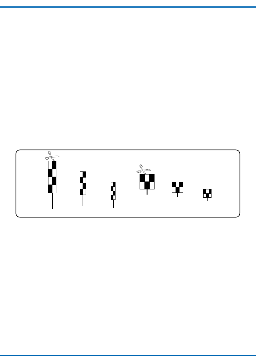
Wenn das Signal ausnahmsweise einmal nicht unmittelbar rechts aufgestellt werden kann, so muss in Höhe des
Signals auf der rechten Seite eine sogenannte Schachbrett-Tafel aufgestellt werden. Diese sind in H0, TT und N
(Abb.1) abgebildet und können ausgeschnitten, auf eine
Stecknadel geklebt und auf die Anlage gesetzt werden.
Die hohe Ausführung wird bei der Aufstellung rechts außerhalb der Gleise und die niedrige zwischen zwei Gleisen
verwendet. Letzteres hat nur einen ganz kurzen Mast.
Abb. 1
3.1 Setting-up of block signals
To prevent that a train drives into another, the rail line is
subdivided into separate segments (”blocks”). In each
block there is only one train allowed to be in it. The following train is not allowed to enter the block before the
rst train has left it completely. A block signal shows the
engine driver if the following block is occupied or free.
Colour light block signals belong to the group of the main
signals and they are the plainest members of this group.
You can nd them at the free parts of the rail lines - mostly at the right side of the rails.
If the signal can not be put up on the right side, a chess-
board-slab has to be put up on this place. You can nd
them at the illustrations in H0, TT and N (g. 1). They can
be cut out, pasted on a pin and put up on your model railway layout. The high model has to be placed at the right
side out of the rails and the lower one between two rails.
The lower slab has only a very short mast.
Fig. 1
Wenn der nachfolgende Block frei ist, so steht das Blocksignal auf „Fahrt” (Hp1 = grün). Kurz nachdem die Zugspitze
das Blocksignal passiert hat, schaltet das Signal auf „Zughalt” (Hp0 = rot) um. Ein nachfolgender Zug muss vor dem
Signal warten. Sobald der erste Zug den Block komplett
verlassen hat, schaltet das Blocksignal auf „Fahrt“ und der
zweite Zug kann in den Block einfahren.
Dieses Block-Sicherungssystem wird auch heute noch
beim Vorbild verwendet und als „Fahren im Raumabstand” bezeichnet.
3.2 Bezeichnung von Blocksignalen
Dem Signal ist eine Tafel mit selbstklebenden Bezeichnungsschildern beigelegt. Schneiden Sie das gewünschte
Bezeichnungsschild aus und kleben Sie es nach Abziehen
der Schutzfolie auf die Nummerntafel des Signals. Hier einige Richtlinien zur korrekten Beschriftung von Blocksignalen:
- Selbsttätige Blocksignale werden mit Hilfe von arabischen Zahlen (1, 2, 3,...) bezeichnet.
- In Richtung der Kilometrierung der Strecke wird vorwärts gezählt (diese wird als „Zählrichtung“ bezeichnet), in die andere Richtung rückwärts.
- In Zählrichtung werden ungerade Zahlen (1, 3, 5 ...)
installiert, in der Gegenrichtung die geraden Zahlen
(2, 4, 6 ...).
H0
If the following block is free, the colour light block sig-
nal shows “go” (Hp1=green). After the head of the train
has passed the block signal, it changes over to “stop”
(Hp0=red). A following train ,has to wait in front of the signal until the rst train has left the block. Then the signal
changes to “go” and the second train is allowed to enter
the block.
This block signalling system is still in use today in the real
world and it is called “Driving with distance spacing“.
3.2 Marking of the block signals
Attached is a board with decals. Cut one of them out and
paste them at the number board. Here are some guidelines for the correct inscription of the block signals:
- Automatical block signals you have to label by arabic
numbers (1, 2, 3,...).
- In the direction of the line-kilometre it is counted for-
ward (it is called “counting direction”), in the other direction backwards.
- Use in counting direction odd (1, 3, 5,...) and in the
other direction even numbers (2, 4, 6,...).
3
Page 4

Abb. 2
1 3 5
Signal auf Hp0 (“Zughalt”) (blau mit roter M.)
Signal auf Hp1 (“Fahrt”) (blau mit grüner M.)
Fig. 2
Bezeichnungs-
schild
Number board
Bahnhof X Blockstrecken Bahnhof Y
Station X Block sections Station Y
0,0 km 1,0 km 2,0 km 3,0 km 4,0 km 5,0 km 6,0 km 7,0 km 8,0 km
2 4 6
3.3 Funktionskontrolle
Vor der Montage ist eine Funktionskontrolle durchzuführen. Zum Testen des Blocksignales sind das gelbe und
das braune Kabel vom Signal an je einem Pol eines
14 - 16 V AC/DC - z.B. Viessmann Art. 5200 - anzuschließen. Beim kurzzeitigen (abwechselnden!) Anschluss der
blauen Kabel an den Pol des Trafos, an dem sich das
braune Signalanschlusskabel bendet, ergeben sich die
Funktionen gemäß Abb. 3.
Abb. 3
Blau mit roter Markierung
Blue with a red mark
Hp0 (Zughalt)
Hp0 (stop)
3.3 Function test
Before mounting you have to make a function test.To test
the block signal you have to connect the yellow and the
brown wire, each to one pole of a 14 - 16 V AC/DC
- e. g. Viessmann item 5200. By alternating connection of
the blue wires to the pole of the model train transformer
where the brown wire has been connected to, you get the
following functions, see g. 3.
Blau mit grüner Markierung
Fig. 3
Blue with a green mark
Hp1 (Fahrt)
Hp1 (go)
3.4 Kabelfarbensystem
Abb. 4
4
3.4 Wire colour system
Train stop (blue with red marking)
Train go (blue with green marking)
Betriebsspannung “Phase” (gelb)
Power supply (yellow)
Betriebsspannung “Masse” (braun)
Power supply “ground” (brown)
Zugbeeinflussungskontakt (rot)
Train stop contact (red)
Zugbeeinflussungskontakt (rot)
Train stop contact (red)
Vorsignalsteuerung (lila)
Distant signal control (lila)
Fig. 4
Page 5

4. Anschluss
Der konventionelle Anschluss der Blocksignale ist in Abb.
5 dargestellt. Die Stromversorgung erfolgt über das braune und gelbe Anschlusskabel. Die mit farbigen Markierungen versehenen blauen Kabel werden über Kontakte
(Einzeltaster, Gleiskontakte, Schaltgleise oder Tastenstellpulte) gegen das braune Anschlusskabel geschaltet.
Je nach der gewählten Schalterstellung erscheint das Signalbild „Zughalt” oder „Fahrt”.
Die beiden roten Anschlusskabel des Hobby-Signals
schalten je nach Signalstellung den Strom im isolierten
Halteabschnitt zu oder ab.
Abb. 5
ca. 2
Loklängen
ca. 2
locomotive
lengths
4021
rot red
rot
red
blau m. roter M.
blue w. red m.
blau m. gr¸ner M.
blue w. green m.
braun brown
gelb yellow
rot
red
rot red
braun brown
4. Connection
The correct connection of a block signal is shown in g.
5. The power supply occurs by the brown and the yellow wire. The blue wires with the coloured marks are
switched by contacts (single keys, reed-contacts, switching rails or push botton panels) to the brown wire. Depending on the position of the key you can see the signal
aspect “stop” or “go”.
The both red wires of the hobby-signal switch the power
at the insulated stop track on or o.
Fig. 5
Hp0
Hp1
Alle Anschlußarbeiten sind nur bei
abgeschalteter Betriebsspannung
Achtung!
durchzuführen!
Fahrstrom
konventionell oder digital
Tracking current
analog or digital
5200
5200
Lichttransformator
Prim‰r 50/60 Hz230 V
Sekund‰r max. 3,25 A52 VA
Nur f¸r trockene R‰ume
Attention!
ta 25∞CIP 40
Gefertigt nach
VDE 0551
EN 60742
Sekund‰r
16 V ~
Prim‰r
230 V ~
Make sure that the power
supply is switched off when
you connect the wires!
Dieses Symbol kennzeichnet einen Schaltkontakt, z.B. einen Reed- (Magnet-) Schalter, Schaltgleis, Einzeltaster oder Tastenstellpult.
Dieses Symbol neben dem Gleis, kennzeichnet eine in Fahrtrichtung rechtsseitige
Trennstelle (z.B. mit Isolierschienenverbindern). Bei Märklin-Gleisen entspricht dieses
einer Mittelleiter-Trennstelle.
In den Anschlussplänen dieser Anleitung
nden Sie häug das nebenstehende Symbol. Es kennzeichnet eine Leitungsverbin-
dung. Die sich hier kreuzenden Leitungen
müssen an einer beliebigen Stelle ihres Verlaufs elektrisch
leitend miteinander in Verbindung stehen. Der Verbindungspunkt muss also nicht exakt an der eingezeichneten Stelle
sitzen, sondern kann z.B. zu einem Stecker, welcher sich an
einer der kreuzenden Leitungen bendet, verlagert werden.
4.1 Weitere Anschlussbeispiele
In den nachfolgenden Beispielen werden Ihnen einige
weitere Möglichkeiten zum Anschluss der Hobby-Signale
vorgestellt. Diese sollen Ihnen Anregungen zur Gestaltung Ihrer Modellbahnanlage geben.
This sign is used for a momentary switching contact like a reed contact, a switching track, a single momentary switch or a
push button panel.
This sign beside the track indicates a
track insulation on the right rail (if you
look in driving direction). If you use the
Märklin system this must be a center rail
insulation insulation.
In the connection diagrams of this instruction you can often see the above
shown symbol. It describes a wire con-
nection. The wires which here are crossing themselves have to be connected electrically at any
point on their way. So the connection point doesn’t need
to be exactly at the shown location. It can be moved e.g.
to a plug which is connected to one of the crossing wires.
4.1 Further connection examples
The following examples will show you some more possibilities to connect the Hobby-signals. These will help you
by designing you model railway layout.
5
Page 6

4.2 Blocksignal und Vorsignal
Sekund‰r
16 V ~
Prim‰r
230 V ~
Gefertigt nach
VDE 0551
EN 60742
Lichttransformator
5200
Nur f¸r trockene R‰ume
Prim‰r 50/60 Hz230 V
Sekund‰r max. 3,25 A52 VA
ta 25∞CIP 40
Tasten-Stellpult 2-begriffig
5547
Viessmann
gn1 gn2ge2ge1
Steuermodul für
Licht-Vorsignal 5220
16 V
bn ge
Art. / Item
4010, 4030,
16 V ~ AC
Art. / Item 5200
Art. / Item
5220
Art. / Item
5547
Art. / Item
4021
Ein Vorsignal macht den Lokomotivführer bereits eine
Weile vorher auf das Signalbild aufmerksam, welches ihn
am nächsten im Fahrweg liegenden Hauptsignal erwartet. Das Vorsignal eines Blocksignals zeigt also entweder
“Fahrt erwarten” (Vr1 = zwei grüne Lichter) oder “Halt erwarten” (Vr0 = zwei gelbe Lichter) an. Beim Vorbild stehen Vorsignale entweder 400m, 700m oder 1000m vor
dem Hauptsignal, je nach zulässiger Höchstgeschwindigkeit auf der Strecke.
Auch das Hobby-Blocksignal kann mit einem Vorsignal
kombiniert werden. Hier wird das Vorsignal Art. 4010 über
das Vorsignalmodul Art. 5220 mitgesteuert. Dazu wird
das lila Kabel am Hobby-Blocksignal mit dem Lichtsignalmodul Art. 5220 entsprechend verbunden. Die Stromversorgung des Vorsignals erfolgt über dessen braunes und
gelbes Anschlusskabel. So zeigt das Vorsignal immer das
Signalbild des Blocksignals an. In Abb. 6 ist die genaue
Verkabelung aufgeführt.
Abb. 6
4.2 Block signal and distant signal
A distant signal shows the engine driver the aspect of the
next main signal in direction before he pass it. The distant
signal shows either “expect go” (Vr1 = two green lights)
or “expect stop” (Vr0 = two yellow lights). Real the distant
signals are placed 400m, 700m or 1000m in front of the
main signal, depending on the allowed high-speed.
The hobby block signal can be combined with a Hobby
distant signal (see g 6). For that both signals have to
be connected by the green marked lilac wire. The yellow
marked lilac wire of the distant signal is not used here.
The electric power is connected to the distant signal
by the brown and the yellow wire. So the distant signal
shows always the same aspect as the main signal.
Fig. 6
4.3 Automatischer Blockbetrieb (Selbstblock)
Mit dem Hobby-Blocksignal kann ein automatischer
Blockstellenbetrieb realisiert werden. Dabei wird die
Fahrspannung im Halteabschnitt vor dem Blocksignal automatisch abgeschaltet, wenn das Signal Hp0, d.h. „Zughalt” anzeigt. Die Steuerung der Signalbegrie erfolgt dabei über Gleiskontakte (z.B. Reedkontakte, Schaltgleise)
durch den fahrenden Zug. Der Kontakt für Hp0 muss
dazu etwas weiter als eine Loklänge hinter dem zugehörigen Halteabschnitt angebracht werden, so dass die Lokomotive sich nicht selbst den Strom unter den Rädern
abschaltet. Der Kontakt für Hp1 muss ausgelöst werden,
sobald der Zug den Block komplett verlassen at. Damit
ergibt sich als ideale Position etwas mehr als eine (maxi-
6
4.3 Automatic block trafc (self-
blocking)
With the hobby block signal an automatic block trac can
be made. The track power of the stoptrack is switched o
automatically, if the signal shows Hp0 (”stop”). The controlling of the signal aspect occurs by track contacts (for example reed contacts or switching tracks). The contact for
Hp0 has to be placed a little bit more than one locomotive
length behind the stop section or the locomotive will switch
of her own power supply. The contact of Hp1 has to be
triggered when the train has completly left the block. So it
has to be placed a litle bit more than one (maximum) train
length behind the next block signal.
To get a realistic block trac there are necessary at least
Page 7

male) Zuglänge hinter dem nächsten Blocksignal.
Für einen vollständig funktionierenden Blockbetrieb sind
mindestens drei solcher Blöcke notwendig. Dann können
zwei Züge entsprechend gesichert verkehren. Für jeden
zusätzlichen Zug ist jeweils eine weitere Blockstelle erforderlich.
Zusätzlich zu den zugbetätigten Schaltkontakten sollte
ein Taster für den manuellen Betrieb vorgesehen werden.
Dieses ist sinnvoll, damit ein Block wieder freigegeben
werden kann, der durch einen von der Anlage heruntergenommenen Zug blockiert ist. Der Anschlussplan für
eine Blockstelle ist in Abb. 7 dargestellt.
4.4 Ansteuerung über Digitalsysteme
Die Hobby-Signale können auch mit einem Digitalsystem
angesteuert werden (Abb. 7). Beim Anschluss der Signale an einen Digital-Decoder wie z.B. Viessmann Art.
5211 (für Märklin-Digital bzw. das Motorola-Format) oder
Viessmann Art. 5280 für das NMRA (DCC)-Format ist
darauf zu achten, dass die braune Signal-Masseleitung,
welche am Versorgungstrafo der Hobby-Signale angeschlossen ist, auch mit der Digitalmasse verbunden ist.
Der Decoder muss positive Schaltimpulse liefern! Dieses
ist bei dem Decoder des Märklin-Digitalsystems (k83) sowie allen Viessmann Decodern der Fall.
three blocks. For each other train one more block is needed. Supplementary to the automatic switches there should
be placed a switch for manual control. This is convenient
to make a block free which was occupied by a train you
have taken away. The connection of one block is shown
in g. 7.
4.4 Controlling by digital systems
Hobby signals can also be controlled by digital systems
(see g. 7). If connecting the signals to digital-decoders like Viessmann item 5211 (for Märklin-Digital or the
Motorola format) or the Viessmann 5280 for the NMRA
(DCC)-Format, it is necessary to connect the brown signal wire (ground), which is connected to the transformer
to the digital ground. The decoder has to send positive
switching pulses. This is ensured by the Märklin digital
decoder (k83) and all decoders made by Viessmann.
Abb. 7
maximale
Zuglänge
maximum
train length
etwas über
Loklänge
a little bit
more than 1
locomotive
Loklängen
locomotive
lengths
eine
one
eine
length
ca. 2
ca. 2
braun
brown
Hp1
nächstes
Blocksignal
next
block signal
Hp0
blau mit roter M.
blue with red m.
4021
rot
red
rot
red
braun brown
blau
blue
braun
brown
Fig. 7
blau
blue
braun
brown
gelb
yellow
Dieses lila Kabel mit grüner
Markierung dient der
rot
red
Steuerung eines Vorsignals!
This lilac wire with green
marking is intended for
controlling a distant signal!
konventionell oder digital
5200
Lichttransformator
Prim‰r 50/60 Hz230 V
Sekund‰r max. 3,25 A52 VA
Nur f¸r trockene R‰ume
ta 25∞CIP 40
Gefertigt nach
VDE 0551
EN 60742
Sekund‰r
16 V ~
Prim‰r
230 V ~
Fahrstrom
Tracking current
analog or digital
7
Page 8

Abb. 8
braun
rot
brown
red
Fig. 8
4E
ON WnP
1 3 2 4 5 6 7 8
Adresse
Weichendecoder 5211
132
rote Markierung
red marking
Hp1
Hp0
4021
ca. 2
Loklängen
4441
4941
braun
braun
rot
brown
brown
red
blau
blue
ca. 2
locomotive
lengths
rot red
rot red
braun brown
5. Technische Daten
Betriebsspannung: 14 - 16 V AC/DC
Kontaktbelastbarkeit (der beiden roten Kabel): 2A
Maße des Antriebskastens: 43 x 16 x 10,5 mm
Digitaldecoder mit
positiven Schaltimpulsen
Digital decoder with
positive switching pulses
grüne Markierung
green marking
Dieses lila Kabel mit grüner
Markierung dient der
Steuerung eines Vorsignals!
This lilac wire with green
marking is intended for
controlling a distant signal!
Masseverbindung zwischen
Signal und Digitalsystem!
Ground connection between
signal and digital system!
Lichttransformator
Prim‰r
230 V ~
Prim‰r 50/60 Hz230 V
Sekund‰r max. 3,25 A52 VA
Nur f¸r trockene R‰ume
ta 25∞CIP 40
Gefertigt nach
VDE 0551
EN 60742
5200
Sekund‰r
16 V ~
rot
red
blau
blue
braun brown
gelb yellow
braun
brown
Fahrstrom digital
Track Power digital
5. Technical data
Operating voltage: 14 - 16 V AC/DC
Max. contact load (the two red wires): 2A
Size of the relay box: 43 x 16 x 10,5 mm
Entsorgen Sie dieses Produkt nicht über den
(unsortierten) Hausmüll, sondern führen Sie
es der Wiederverwertung zu.
Änderungen vorbehalten. Keine Haftung für Druckfehler
und Irrtümer.
Die aktuelle Version der Anleitung nden Sie auf der
Viessmann Homepage unter der Artikelnummer.
Modellbauartikel, kein Spielzeug! Nicht geeignet für Kinder
DE
unter 14 Jahren! Anleitung aufbewahren!
Model building item, not a toy! Not suitable for children
EN
under the age of 14 years! Keep these instructions!
Ce n’est pas un jouet. Ne convient pas aux enfants de
FR
moins de 14 ans ! C’est un produit décor! Conservez cette
notice d’instructions!
Não é um brinquedo!Não aconselhável para menores de
PT
14 anos. Conservar a embalagem.
Modelltechnik GmbH
Bahnhofstraße 2a
D - 35116 Hatzfeld-Reddighausen
8
www.viessmann-modell.de
Do not dispose of this product through (unsorted)
domestic waste, supply it to recycling instead.
Subject to change without prior notice. No liability for
mistakes and printing errors.
You will nd the latest version of the manual on the
Viessmann website using the item-No.
Modelbouwartikel, geen speelgoed! Niet geschikt voor
NL
kinderen onder 14 jaar! Gebruiksaanwijzing bewaren!
Articolo di modellismo, non è un giocattolo! Non adatto
IT
a bambini al di sotto dei 14 anni! Conservare instruzioni
per l’uso!
Artículo para modelismo ¡No es un juguete! No
ES
recomendado para menores de 14 años! Conserva las
instrucciones de servicio!
Stand 04
Made in Europe
07/2018
98652
Ka/Ir
 Loading...