

Page 1

Installation Instructions
for use by heating contractor
Replacement of Control Console
for Vitodens 100-WB1A
, Part No. 7826 987, 7826 988
Safety and Installation Requirements
Please ensure that these instructions are read and understood before commencing installation. Failure to comply with the
instructions listed below can cause product/property damage, severe personal injury, and/or loss of life.
Please file in Service Binder
Working on the equipment
The installation, adjustment, service,
and maintenance of this product must
be done by a licensed professional
heating contractor who is qualified and
experienced in the installation, service,
and maintenance of hot water boilers.
There are no user serviceable parts on
the boiler, burner, or control.
Remove front cover panel and expose control
Ensure main power supply to
equipment, the heating system, and all
external controls has been deactivated.
Close main gas supply valve. Take
precautions in both instances to avoid
accidental activation of power during
service work.
It is not permissible to perform service
work on any component parts ensuring
safe operation of the heating system.
When replacing parts, use original
Viessmann or Viessmann approved
replacement parts.
Ensure that theVitodens 100
Service Instructions are
referenced.
C
A
1. Remove the screw at the top of
boiler .
2. Press down on springs at bottom
of boiler and remove the front
enclosure panel .
3. Flip control console down .
D
7826 988 II CA 03/2009
B
Page 2

Removing the control unit
1. Flip control unit down and out
towards you. The control unit is held
in place with a spring loaded clip A.
A
2. Slide unit to the left to remove.
IMPORTANT
The control unit has labels and stickers
containing important information. Read
and follow their respective instructions.
3. Tilt down the control to remove back
cover (shield).
4. Release tabs on both sides of the
console.
2
5. Expose wiring connectors.
Page 3

Removing the control unit (continued)
6. Remove connectors.
7. Cut cable tie from the base.
8. Remove complete control console
from the base (left side first).
3
Page 4

Installation
1. Install new control (starting from
right side).
2. Reconnect all wiring harnesses
(connectors are numbered which
correspond to the numbers printed
on the circuit board).
3. Use two cable ties (field supplied) to
secure the harness to the control
base.
4. Reinstall back cover (shield).
4
Page 5
Installation (continued)
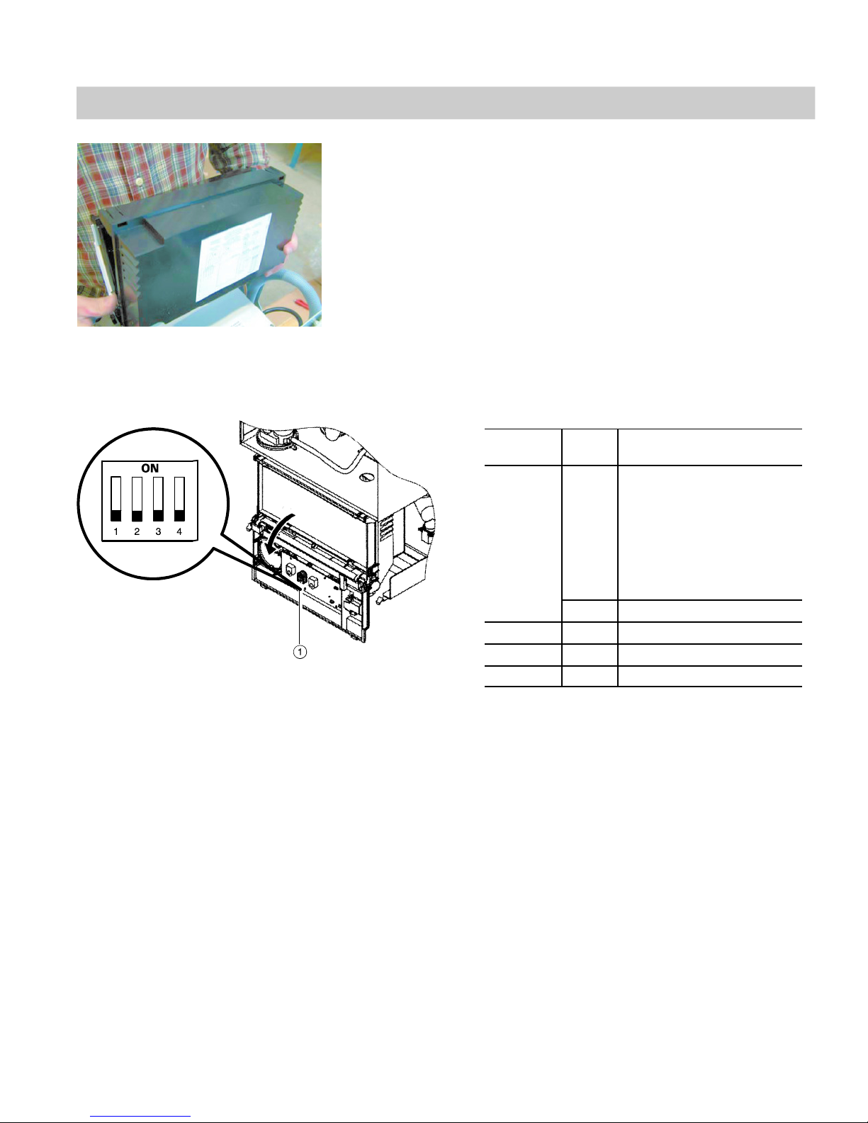
S1
Factory default settings
for S1 DIP switch
1 Dip switch S1
5. Reinstall front cover panel.
6. Verify DIP switch settings.
DIP switch settings - S1
Dip switch
number
1 OFF Pump is ON during call for
2 OFF Do not adjust
3 OFF Do not adjust
4 OFF Do not adjust
Setting Explanation
heat. After call for heat
(RT-Terminal) is satisfied
pump post-purges for 12
minutes.
After DHW/external heat
demand (ST-Terminal) is
satisfied, pump post-purges
for 1.5 minutes.
ON Pump operates continuously
5
Page 6

Reinstalling the control unit
1. Hook in control unit.
2. Flip control upward and lock into
position.
CAUTION
Electrical cables may become
damaged if in contact with hot
components.
When running and securing
connecting cables on site, ensure
that the maximum permissible
temperatures of the cables are not
exceeded.
Reinstalling the front cover panel
1. Hook in front cover panel.
2. Press in bottom portion of front
cover panel until it locks into
position.
3. Fasten with screw at the top part of
the boiler.
IMPORTANT
Read and follow, where applicable, the
safety instructions of all labels and
stickers attached to boiler surfaces. Do
not remove any of these instructions.
Contact Viessmann if any replacement
labels are required.
6
Page 7

Wiring diagram
External Connections (Field Wiring)
DHW
PUMP
PUMP
7
Page 8

Printed on environmentally friendly
(recycled and recyclable) paper.
Viessmann Manufacturing Company (U.S.) Inc.
45 Access Road
Warwick, Rhode Island • 02886 • USA
1-800-288-0667 • Fax (401) 732-0590
www.viessmann-us.com • info@viessmann-us.com
8
Viessmann Manufacturing Company Inc.
750 McMurray Road
Waterloo, Ontario • N2V 2G5 • Canada
1-800-387-7373 • Fax (519) 885-0887
www.viessmann.ca • info@viessmann.ca
Technical information subject to change without notice.
7826 988 II v1.0
 Loading...