

Page 1
AC voltage: Operation with AC voltage could cause some
ickering. We recommend to use the Viessmann power
module item-No. 5215 (g.6) which is sufcient for approx.
100 LEDs. Connect the cable to the diode with the brown
output socket (g. 4).
5. Safety information
Caution:
Risk of injury!
Due to the detailed reproduction of the original and the
intended use, this product can have peaks, edges and
breakable parts. For installation tools are required.
Electrical hazard!
Never put the connecting wires into a power socket!
Regularly examine the transformer for damage. In case of
any damage, do not use the transformer!
Installation and electrical wiring may only be carried out
while the power supply is switched off. Only use transformers compliant with VDE / EN standards.
6338 (1 Stück/piece)
6339 (7 Stück/pieces)
H0 Deckenstrahler, LED weiß
H0 Ceiling spotlight, LED white
Modellbauartikel, kein Spielzeug! Nicht geeignet für
DE
Kinder unter 14 Jahren! Anleitung aufbewahren!
Model building item, not a toy! Not suitable for children
EN
under the age of 14 years! Keep these instructions!
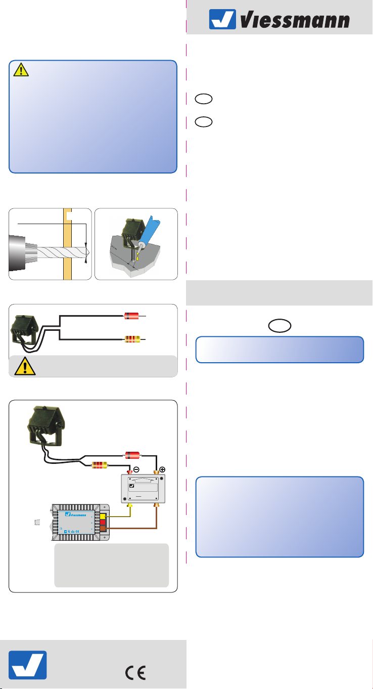
Abb. 1
Fig. 1 Abb. 2
Fig. 2
Ø 2 mm
diode
rt bn
E
viessmann
Powermodul
Braune Massebuchsen
ge bn
gelb
yellow
/ brown
+
14-24 V=/~
(AC / DC)
–
zu den Decodern
5215
nicht koppeln !
max. 24 V~
Fig. 3
Fig. 4
T
Abb. 3
schwarz
black
schwarz
black
Diode
diode
Widerstand
resistor
Diode und Widerstand nicht abschneiden.
Never cut off diode and resistor.
Abb. 4
Abb. ähnlich
Fig. like
6338
6339
5215
16 V~
16 V~
braun
Diode
Widerstand
resistor
z. B. 5200
e. g. 5200
16 V
5200
Lichttransformator
10 V
Sekundär
Primär
0-10-16 V~
230 V~
Primär 230 V 50 - 60 Hz
Sekundär max. 3,25 A52 VA
ta 25°CIP 40
0 V
Nur für trockene Räume
Gefertigt nach
VDE 0570
EN 61558
TIPP: Powermodul 5215
● Verhindert Flackern bei Wechselstrom.
● Annähernd doppelte Helligkeit
gegenüber reinem Wechselstrombetrieb.
TIP: Power module 5215
● Avoids flickering with AC power supply.
● Approx. double brightness of the lamps.
Die jeweils aktuellste Version der Anleitung nden Sie auf
der Viessmann-Homepage unter der Artikelnummer.
The latest version of the manual can be looked up at the
Viessmann homepage using the item-No.
Bedienungsanleitung
Operation Manual
DE
Tipp:
Perfekt zur Montage am kibri Artikel
49000 Moderner Busbahnhof in Halle/Saale.
1. Wichtige Hinweise
Bitte lesen Sie vor der ersten Anwendung des Produktes bzw.
dessen Einbau diese Bedienungsanleitung aufmerksam durch
und bewahren Sie sie auf. Sie ist Teil des Produktes.
Packungsinhalt überprüfen
Kontrollieren Sie den Lieferumfang auf Vollständigkeit:
Art.-Nr. 6338
- 1 Deckenstrahler
- 1 Tauschkonsole
- diese Anleitung
Das Produkt richtig verwenden
Dieses Produkt ist bestimmt:
- Zum Einbau in Modelleisenbahnen bzw. Dioramen.
- Zum Anschluss an einem Modellbahntransformator
(z. B. Art.-Nr. 5200) bzw. an einer Modellbahnsteuerung
mit zugelassener Betriebsspannung.
- Zum Betrieb in trockenen Räumen.
Jeder darüber hinausgehende Gebrauch gilt als nicht
bestimmungsgemäß. Für daraus resultierende Schäden
haftet der Hersteller nicht.
2. Einleitung
Dieser Deckenstrahler erzeugt durch die SMD-LED ein zum
Lampenmodell passendes Licht. Stromaufnahme und
Wärmeentwicklung sind sehr gering. Die Lebensdauer der
LED ist praktisch unbegrenzt, so dass ein Wechsel des
Leuchtmittels entfällt.
Art.-Nr. 6339
- 7 Deckenstrahler
- 7 Tauschkonsolen
- diese Anleitung
Viessmann
Modellspielwaren GmbH
Am Bahnhof 1
D - 35116 Hatzfeld (Eder)
4
www.viessmann-modell.de
87838
Stand 01/sw
06/2014
Ho/Eg
1
Page 2
3. Einbau
- Deckenstrahler vorsichtig aus der Verpackung nehmen.
- Vor dem Einbau auf Funktion prüfen.
Vorsicht:
Alle Anschlussarbeiten nur bei abgeschalteter Betriebsspannung durchführen!
- Am Einbauort ein Loch (Ø 2 mm) zur Montage bohren
(Abb. 1).
- Die Anschlusskabel von außen durch das Loch hindurchführen und Konsole aufkleben, z. B. mit einem handels-
üblichen Sekundenkleber (Abb. 2).
Hinweis:
Möchten Sie den Deckenstrahler 6338 an den kibri Artikel
49000 Moderner Busbahnhof in Halle/Saale montieren,
so tauschen Sie bitte die am Produkt bendliche Konsole
gegen die beiliegende Konsole mit den beiden Zapfen
aus. Diese Konsole ist speziell für den kibri Artikel 49000
konstruiert.
Die Deckenstrahler des Sets 6339 sind werksseitig bereits
mit den Konsolen zur Montage am kibri Artikel 49000
Moderner Busbahnhof in Halle/Saale ausgestattet. Die
genaue Montage entnehmen Sie bitte der Aufbauanleitung
des Art. 49000. Möchten Sie die Reektoren 6339 an anderer Stelle montieren, so tauschen Sie die Konsolen bitte
gegen die beiliegenden Universal-Konsolen aus.
Lassen Sie beim Anschließen der Kabel hinter der Leuchte
eine Schleife von ca. 2-3 cm Länge, damit Sie die Leuchte bei
eventuellen Arbeiten aus der Montagebohrung ziehen können.
Vorsicht:
Widerstand und Diode an den Enden der Anschlussdrähte
sind für die Funktion erforderlich. Keinesfalls entfernen
(Abb. 3)! Widerstände nicht mit Isolationsmaterial umhüllen, da sonst keine ausreichende Kühlung möglich ist!
4. Anschluss
Betriebsspannung: 14-24V AC~ oder DC=
Stromaufnahme: ca. 10 mA
Schließen Sie die LED-Leuchte an den Lichtausgang eines
Modellbahntransformators (z. B. Art.-Nr. 5200) an (Abb. 4).
Gleichspannung: Verbinden Sie die Diode (rotes Bauteil mit
schwarzer Markierung) mit dem Plus-Pol des Netzteils.
Wechselspannung: Bei Betrieb mit Wechselspannung kann
es zu leichtem Flackern kommen. Daher empfehlen wir den
Betrieb mit dem Viessmann-Powermodul Art.-Nr. 5215 (Abb.
4). Ein Powermodul ist ausreichend für ca. 100 LED-Leuchten.
Verbinden Sie die Diode des Anschlusskabels mit der braunen
Ausgangsbuchse (Abb. 4).
14-16V AC~ mit 5215 Powermodul
5. Sicherheitshinweise
Vorsicht:
Verletzungsgefahr!
Aufgrund der detaillierten Abbildung des Originals bzw.
der vorgesehenen Verwendung kann das Produkt Spitzen,
Kanten und abbruchgefährdete Teile aufweisen. Für die
Montage sind Werkzeuge nötig.
Stromschlaggefahr!
Die Anschlussdrähte niemals in eine Steckdose einführen!
Verwendetes Versorgungsgerät (Transformator, Netzteil)
regelmäßig auf Schäden überprüfen. Bei Schäden am
Versorgungsgerät dieses keinesfalls benutzen!
Alle Anschlussarbeiten nur bei abgeschalteter Betriebsspannung durchführen! Stromquellen so absichern, dass
es im Falle eines Kurzschlusses nicht zum Kabelbrand
kommen kann. Nur handelsübliche und VDE-geprüfte
Modellbahntransformatoren verwenden!
ENDE
Hint:
Fits perfectly to kibri product
49000 modern bus terminal Halle/Saale.
1. Important information
Please read this manual completely and attentively before
using the product for the rst time. Keep this manual. It is part
of the product.
Checking the package contents
Check the contents of the package for completeness:
Item-No. 6338
- 1 Ceiling spotlight
- 1 exchange console
- this manual
Using the product for its correct purpose
This product is intended:
- For installation in railroad model layouts and dioramas.
- For connection to an authorized model railroad
transformer (e. g. item-No. 5200).
- For operation in dry rooms only.
Using the product for any other purpose is not approved
and is considered incorrect. The manufacturer is not
responsible for any damage resulting from the improper
use of this product.
2. Introduction
This lamp produces by SMD-LED the light which is suitable
for the lamp model. Low heat build-up and power input. Nearly
unlimited lifetime of the LED, so no more change is required.
3. Mounting
- Remove the ceiling spotlight carefully from the package.
- Check function before mounting.
Caution:
Installation and electrical wiring may only be carried out
while the power supply is switched off.
- Drill a hole of Ø 2 mm at the mounting place (g. 1).
- Put the cables from outside the hole and x the console,
e.g. with a commercial glue.
Hint:
To mount the ceiling spotlight 6338 please to the kibri
item-No. 49000 bus terminal Halle/Saale exchange the
xed console (on the product) to attached console (equipped with two pins). The console is a special construction
for the kibri item-No. 49000.
The ceiling spotlights of the extension set item-No. 6339
are mounted with the consoles on the kibri item-No.
49000 bus terminal Halle/Saale. Installation is explained
in our manual of 49000. To mount reectors 6339 at other
positions please exchange consoles.
Connecting the cable, please leave approx. 2-3 cm behind
the lamp to create a loop, which enables you to pull the lamp
out of the assembly drilling, if necessary.
Caution:
Resistor and diode at the cables are needed for proper
function of the lamp. Never cut them off!
Never cover resistor or diode with insulation material,
because they have to be cooled by surrounding air!
4. Connection
Operating voltage: 14-24V AC~ or DC=
Operating current: approx. 10 mA
Connect the LED-lamp to the lighting power output of a model
railroad transformer (e. g. item-No. 5200) or power supply as
shown in g. 5 and / or 6.
DC voltage: Connect the diode (red part with black mark)
with the plus pole of the power supply.
14-16V AC~ with 5215 Power module
Item-No. 6339
- 7 Ceiling spotlights
- 7 exchange consoles
- this manual
32
 Loading...