

Page 1
Bedienungsanleitung
~
=
Operation Manual
Soundmodul
mit/ohne Synchronsteuerung
Sound module
with/without synchronous control
1. Wichtige Hinweise ....................................... 2
2. Einleitung .................................................... 3
3. Einbau ......................................................... 3
4. Anschluss .................................................... 4
5. Betrieb ......................................................... 10
6. Notizen ........................................................ 11
7. Fehlersuche und Abhilfe .............................. 12
8. Technische Daten ........................................ 12
14 – 16 V
=/~
1. Important information ................................... 2
2. Introduction .................................................. 3
3. Mounting ...................................................... 3
4. Connection ................................................... 4
5. Operation ..................................................... 10
6. Notes ........................................................... 11
7. Trouble-shooting .......................................... 12
8. Technical data ............................................. 12
AC
DC
Page 2
DE EN
1. Wichtige Hinweise
Bitte lesen Sie vor der ersten Anwendung des
Produktes bzw. dessen Einbau diese Bedienungsanleitung komplett und aufmerksam durch.
Bewahren Sie diese auf. Sie ist Teil des Produktes.
1.1 Sicherheitshinweise
Vorsicht:
Verletzungsgefahr!
Aufgrund der detaillierten Abbildung des Originals bzw. der vorgesehenen Verwendung kann
das Produkt Spitzen, Kanten und abbruchgefährdete Teile aufweisen. Für die Montage sind
Werkzeuge nötig.
Stromschlaggefahr!
Die Anschlussdrähte niemals in eine Steckdo-
se einführen! Verwendetes Versorgungsgerät
(Transformator, Netzteil) regelmäßig auf Schäden überprüfen. Bei Schäden am Versorgungsgerät dieses keinesfalls benutzen!
Alle Anschluss- und Montagearbeiten nur bei
abgeschalteter Betriebsspannung durchführen!
Ausschließlich nach VDE/EN-gefertigte
Modellbahntransformatoren verwenden!
Stromquellen unbedingt so absichern, dass es
bei einem Kurzschluss nicht zum Kabelbrand
kommen kann.
1.2 Das Produkt richtig verwenden
Dieses Produkt ist bestimmt:
- Zum Einbau in Modelleisenbahnanlagen und
Dioramen.
- Zum Anschluss an einen Modellbahntransformator (z. B. Art.-Nr. 5200) bzw. an einer Modellbahnsteuerung mit zugelassener Betriebsspannung.
- Zum Betrieb in trockenen Räumen.
Jeder darüber hinausgehende Gebrauch gilt als
nicht bestimmungsgemäß. Für daraus resultierende Schäden haftet der Hersteller nicht.
1.3 Packungsinhalt überprüfen
Kontrollieren Sie den Lieferumfang auf Vollstän-
digkeit:
- Soundmodul
- Montagematerial ( 2 Schrauben, 6 Stecker)
- Anleitung
1. Important information
Please read this manual completely and attentively before using the product for the rst time.
Keep this manual. It is part of the product.
1.1 Safety instructions
Caution:
Risk of injury!
Due to the detailed reproduction of the original
and the intended use, this product can have
peaks, edges and breakable parts.
For installation tools are required.
Electrical hazard!
Never put the connecting cables into a power
socket! Regularly examine the transformer for
damage. In case of any damage, do not use the
transformer!
Make sure that the power supply is switched
off when you mount the device and connect the
cables!
Only use VDE/EN tested special model train
transformers for the power supply!
The power sources must be protected to prevent the risk of burning cables.
1. 2 Using the product for its correct purpose
This product is intended:
- For installation in model railroad layouts and
dioramas.
- For connection to an authorized model
railroad transformer (e. g. item-No. 5200).
- For operation in dry rooms only.
Using the product for any other purpose is not
approved and is considered incorrect. The manufacturer is not responsible for any damage resulting from the improper use of this product.
1.3 Checking the package contents
Check the contents of the package for completeness:
- Sound module
- Mounting material (2 screws, 6 plugs)
- Manual
2
Page 3
Mount the module with loudspeaker on top!
2. Einleitung
Genießen Sie die kleinen Welten mit allen Sinnen.
Noch lebendiger werden Modellbahnen und
Dioramen mit passender Geräuschkulisse.
Viessmann Soundmodule sind mit Geräuschen
für verschiedene Themen erhältlich. Sie sind dank
ihres eingebauten Lautsprechers einfach zu installieren, sehr kompakt und sofort betriebsbereit.
Die Lautstärke ist selbstverständlich regelbar.
Die auf den Modulen enthaltenen Geräusche sind
fest installiert und nicht austauschbar.
2.1 Synchronsteuerung
Verschiedene Module verfügen über einen Steuereingang bzw. Steuerausgang und erzeugen bewegungssynchrone Sounds passend zu geeigneten
Modellen aus der Serie eMotion – Bewegte Welt.
Im Standardbetrieb ohne Synchronsteuerung
spielt das Modul die jeweilige Geräuschkulisse
in Schleife ab. Bei Synchronsteuerung mit einem
geeigneten eMotion-Artikel spielt das Modul die
Geräuschkulisse passend zu der Bewegung des
Modells ab.
Bei einigen Modellen (z. B. Hubschrauber) steuert
das Soundmodul das Modell. Hierzu ist bei entsprechenden Soundmodulen zusätzlich ein Synchronausgang vorhanden. Dadurch ist es möglich,
Geräusche und Bewegungen in einem sinnvollen
Zusammenhang darzustellen (z. B. Starten des
Motors, Beginn der Drehbewegung des Rotors,
Schnelle Rotorbewegung, Start, ...). Informationen
zum Anschluss nden Sie ausführlich in Kapitel 4.
2. Introduction
Enjoy the small worlds with all your senses. Model
train layouts and dioramas become even more
realistic and alive by the appropriate background
sound.
Viessmann sound modules are available with
sounds tting for different subjects. They are very
compact, immediately operational and easy to install due to the integrated loudspeaker. Of course,
the volume can be adjusted. The sounds of the
modules are an integral part and can not be exchanged.
2.1 Synchronized control
Various modules are equipped with a control input
respectively control output so that they can generate motion synchronized sounds suitable for the
respective models of the eMotion series.
In the standard operation mode without synchronized control the module will play the respective
background noise in a loop. If the module receives
a synchronizing impulse emitted from an appropriate eMotion-article it plays the background noise
according to the movements of this functional
model.
In case of some special models, e. g. helicopter,
the sound module itself controls the functional
model. Therefore the specic sound module is
equipped with an additional synchronized output
which enables synchronization of sounds and
movements (e. g. starting of the motor, beginning
of the rotor, rotating movement, ...).
You can nd information concerning the connection in chapter 4.
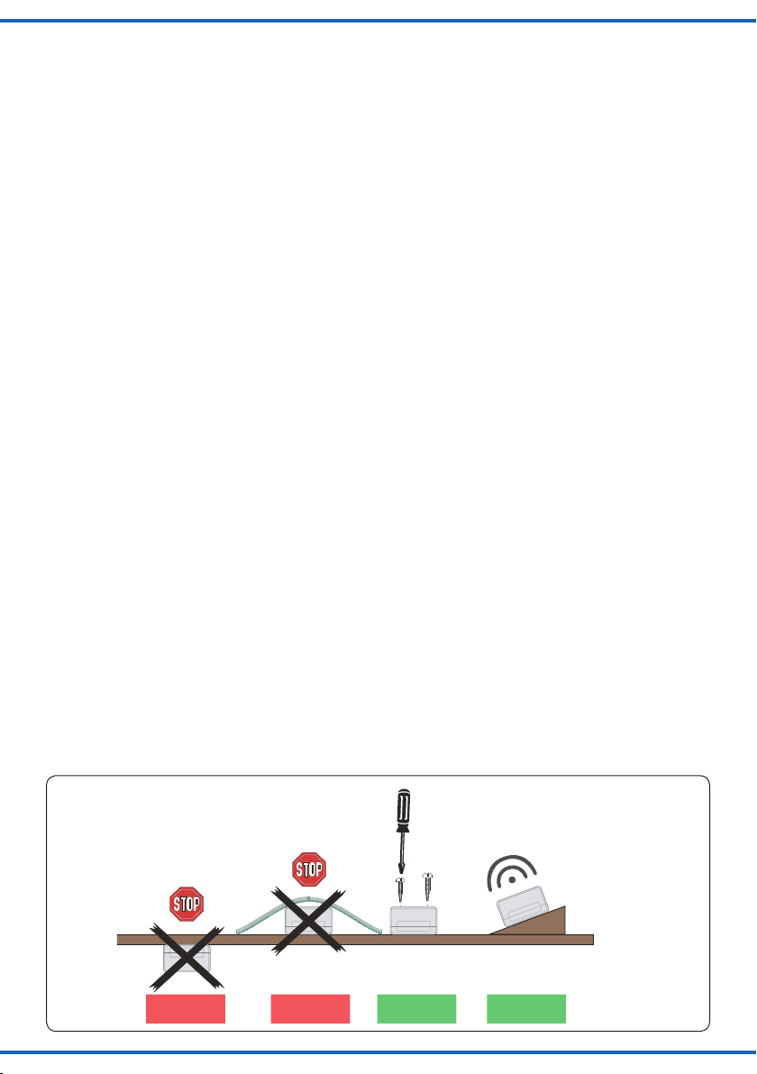
3. Einbau
Die Befestigung des Bausteins erfolgt mit den beiliegenden Schrauben. Für optimalen Klang beachten Sie folgende Hinweise:
Abb. 1
Einbaulage für Soundmodule
Mounting of sound modules
Falsch RichtigFalsch
wrong correctwrong
3. Mounting
Fix the module with the enclosed screws. To ensure an optimal sound reproduction of the module,
please note the following tips:
Lautsprecherschlitze nicht abdecken!
Mit Lautsprecher nach oben montieren!
Do not cover loudspeaker slots!
Optimal
ideal
Fig. 1
3
Page 4
1. Der Lautsprecher ist im Modul integriert. Für
eine gute Schallverteilung darf die Oberseite
des Moduls nicht verdeckt sein.
2. Soundmodul möglichst in Richtung der Zuschauer/Zuhörer ausrichten, also keine ÜberKopf-Montage unter der Anlage.
3. Das Soundmodul sollte sich dort benden, wo
das entsprechende Funktionsmodell auf Ihrer
Anlage vorkommt. Sie können das Modul auch
auf der Anlage (z. B. in einem Gebäude etc.)
einbauen. So erreichen Sie noch besseren
Klang und eine bessere Übereinstimmung von
sichtbarer und hörbarer Geräuschquelle.
1. The loudspeaker is an integrated part of the
module. The upper surface of the module must
always be uncovered in order to enable a good
sound dispersion.
2. The sound module must always be adjusted to the
direction of the spectator, so please no upside down
mounting under the layout.
3. The sound module should be installed near to the
respective functional model on your layout. You can
install the module on the layout itself, e. g. in a building. This way you can even have a better sound and
an optimal concordance between the visible and the
audible sound source.
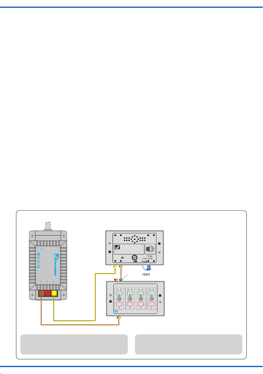
4. Anschluss
Geeignete Kabel: Der geringe Strombedarf des
Soundmoduls erlaubt es, entsprechend klein dimensionierte Kabel, die sich gut versteckt verlegen lassen, zu verwenden. Wir empfehlen Litze
mit einem Querschnitt von 0,14 mm² (z. B. Viessmann Art.-Nr. 6860 – 6869 oder 68603 – 68693).
Das Soundmodul verfügt nicht über einen EinAus-Schalter. Wenn Sie das Soundmodul ausschalten bzw. von der Stromversorgung trennen
möchten, bauen Sie in eine der beiden Stromversorgungsleitungen (braun oder gelb) einen Schalter ein (s. Abb. 2).
Beachten Sie die Sicherheitshinweise oben.
Schließen Sie das Soundmodul gemäß Abb. 2 an
die Stromversorgung an.
Abb. 2
Nur für trockene Räume
Gefertigt nach
VDE 0570
EN 61558
Sekundär max. 3,25 A52 VA
ta 25°CIP 40
0 V
Primär 230 V 50 - 60 Hz
Anschluss der Stromversorgung/Connection of power supply unit
z. B. / e. g. 5570
230 V~
Primär
Lichttransformator
5200
0-10-16 V~
Sekundär
16 V
10 V
z. B. / e. g. 5200
Synchron-
ausgang
viessmann
Soundmodul
14-16V
~ / =
Universal Ein-Aus-Umschalter
4. Connection
Fitting cables: Due to the low current consumption
thin cables can be used which can easily be hidden. It
is recommended to use a cross section of 0,14 mm²
(e. g. Viessmann item-No. 6860 – 6869 or 68603 –
68693).
The sound module has no on-off-switch. In case
you want to switch off or disconnect the sound
module from power supply, you can add a switch
in one of the two power supply wires (brown or
yellow), see g. 2.
Note the safety instructions mentioned above.
Connect the sound module to the power supply
according to g. 2.
Fig. 2
Synchron-
eingang
55xx
intern / extern
/ green
grün
z. B. / e. g. 5550
/ yellow
gelb
braun
/ brown
Abweichender Anschluss bei den Soundmodulen
Art.-Nr. 5556, 5557, 5559 und 5560. Beachten Sie
die Anschlussgraken in den Zusatzanleitungen.
4
viessmann
5550
The connection of sound modules item-No. 5556,
5557, 5559 and 5560 is different. Observe the con-
nection patterns in the supplementary manuals.
Page 5

4.1 Anschluss des Synchroneingangs
(nur Soundmodule Art.-Nr. 5570, 5572, 5574)
Dieses Kapitel beschreibt den Anschluss geeigneter eMotion-Artikel mit Steuerausgang für bewegungssynchronen Sound an Soundmodulen
mit entsprechendem Eingang.
4.1 Connection of the synchronized input
(only sound modules item-No. 5570, 5572, 5574)
This chapter describes how to connect an appropriate eMotion-item equipped with a control output
for motion synchronized sounds to sound modules
with appropriate input.
Hinweis:
Einen optimalen Effekt erreichen Sie, wenn Sie
den geräuschauslösenden eMotion-Artikel und
das Soundmodul in unmittelbarer Nähe
zueinander platzieren.
– Schalten Sie die Stromversorgung des
eMotion-Artikels und des Soundmoduls aus.
– Verbinden Sie die beiden schwarzen Steuer-
leitungen des eMotion-Artikels mit den beiden
Synchroneingangsbuchsen des Soundmoduls
(siehe Abb. 3).
Abb. 3
Achtung: Immer zuerst
die beiden Steuerleitungen
anschließen, um Kurzschluss zu vermeiden.
z. B. / e. g. 5200
z. B. / e. g. 5570
230 V~
Primär
Nur für trockene Räume
Lichttransformator
Primär 230 V 50 - 60 Hz
Sekundär max. 3,25 A52 VA
ta 25°CIP 40
Gefertigt nach
VDE 0570
EN 61558
5200
0-10-16 V~
Sekundär
16 V
10 V
0 V
viessmann
Soundmodul
14-16V
~ / =
Universal Ein-Aus-Umschalter
Tip:
You get the most efcient effect if you place the noise-releasing eMotion-item to the sound module as
near as possible.
– Switch off the power supply of the eMotion-item and
the sound module.
– Connect the two black control wires of the eMotion-
item to the two synchronized input connection jacks
of the sound module (see g. 3).
Caution: Connect at rst
the control wires (black)
to avoid short circuit.
Synchron-
eingang
55xx
intern / extern
grün
/ green
schwarz
black
z. B. / e. g. 1515
Fig. 3
viessmann
/ yellow
gelb
braun
/ brown
4.2 Anschluss des Synchronausgangs
(nur Soundmodule Art.-Nr. 5556, 5557, 5573)
Bei diesen Soundmodulen steuert das Soundmodul
das Modell. Beachten Sie bitte die folgenden Abbil-
dungen:
5550
4.2 Connection of the synchronized output (only
sound modules item-No. 5556, 5557, 5573)
In case of these sound modules, the sound module
itself controls the functional model. Therefore it is
necessary to consider the corresponding gures:
5
Page 6

Soundmodul Art.-Nr. 5556 an Art.-Nr. 5100, 5700,
Sekundär
0-10-16 V~
16 V
Primär
230 V~
Gefertigt nach
VDE 0570
EN 61558
Lichttransformator
5200
Nur für trockene Räume
Primär 230 V 50 - 60 Hz
Sekundär max. 3,25 A52 VA
ta 25°CIP 40
10 V
0 V
viessmann
5550
Universal Ein-Aus-Umschalter
viessmann
Soundmodul
Synchron-
eingang
14-16V
~ / =
55xx
intern / extern
Synchron-
ausgang
gelb
braun
z. B. / e. g. 5200 z. B. / e. g. 5100 / 5700 / 5900
grün
5556
z. B. / e. g. 5550
Gleichspannungsbetrieb:
Synchroneingang mit Pol der
Spannungsquelle verbinden.
Synchroneingang mit Pol der
Spannungsquelle verbinden.
/ brown
/ yellow
/ green
DC operation:
Connect “Synchroneingang” to
pole of the power supply.
Connect “Synchroneingang” to
pole of the power supply.
blau mit roter Markierung
blue with red marking
blau mit grüner Markierung
blue with green marking
oder 5900 (Abb. 4),
Soundmodul Art.-Nr. 5557 an Art.-Nr. 5164 (Abb. 5),
Soundmodul Art.-Nr. 5556 an Art.-Nr. 5104 oder 5107
(Abb. 6) und
Soundmodul Art.-Nr. 5573 an Art.-Nr. 1591 (Abb. 7).
Art.-Nr. 5556/5557: Zum Ein- und Ausschalten des
Modells sowie des Soundmoduls benötigen Sie einen
Schalter, der an den Buchsen „Synchroneingang“ angeschlossen ist. Viessmann empehlt hierzu den
Universal-Ein-Aus-Umschalter Art.-Nr. 5550.
Sound module item-No. 5556 to item-No. 5100,
5700 or 5900 (g. 4),
sound module item-No. 5557 to item-No. 5164 (g. 5),
sound module item-No. 5556 to item-No. 5104 or
5107 (g. 6) and
sound module item-No. 5573 to item-No. 5119 (g. 7).
Item-No. 5556/5557: You need a switch to switch
on/off the model as well as the sound module. The
switch is connected to the connection jacks “synchronous input”. Viessmann recommends the universal
on-off switch item-No. 5550.
Abb. 4
Anschlussschema gilt ausschließlich für Art-Nr. 5100/5700/5900 an Soundmodul Art.-Nr. 5556
The wiring is only valid for item-No. 5100/5700/5900 to sound module item-No. 5556
Abb. 5
Anschlussschema gilt ausschließlich für Art.-Nr. 5164 “Hubschrauber” an Soundmodul Art.-Nr. 5557
The wiring is only valid for item-No. 5164 “Helicopter” to sound module item-No. 5557
z. B. / e. g. 5200 z. B. / e. g. 5164
230 V~
Primär
Nur für trockene Räume
Lichttransformator
Primär 230 V 50 - 60 Hz
Gefertigt nach
VDE 0570
EN 61558
Sekundär max. 3,25 A52 VA
ta 25°CIP 40
0-10-16 V~
Sekundär
10 V
0 V
5200
16 V
/ yellow
gelb
braun
schwarz
black
/ brown
Synchron-
ausgang
viessmann
Soundmodul
14-16V
~ / =
55xx
/ green
grün
Synchron-
eingang
intern / extern
5557
6
Gleichspannungsbetrieb:
Synchroneingang mit Pol der
Spannungsquelle verbinden.
Synchroneingang mit Pol der
Spannungsquelle verbinden.
DC operation:
Connect “Synchroneingang” to
pole of the power supply.
Connect “Synchroneingang” to
pole of the power supply.
Universal Ein-Aus-Umschalter
viessmann
5550
z. B. / e. g. 5550
Fig. 4
Fig. 5
Page 7

z. B. / e. g. 5300 Commander
Commander
Sekundär
0-10-16 V~
16 V
Primär
230 V~
Gefertigt nach
VDE 0570
EN 61558
Lichttransformator
5200
Nur für trockene Räume
Primär 230 V 50 - 60 Hz
Sekundär max. 3,25 A52 VA
ta 25°CIP 40
10 V
0 V
z. B. / e. g. 5200
grün
orange
green
orange
viessmann
Powermodul
5215
T
E
ge bn
Braune Massebuchsen
nicht koppeln !
max. 24 V~
rt bn
zu den Decodern
5215
Positiv
positive
viessmann
4-fach-Blinkgerät 5065
16 V ~
bn
1
ge
ge
4
32
zu den Andreaskreuzen
To the St. Andrews crosses
braun / brown
gelb / yellow
grün / green
orange / orange
blau / blue
330 Ohm
0,25 W
Geschwindigkeit:
Originalstand: 6 sec
nach dem Schnitt: 3 sec
Barrier speed:
Original: 6 sec
After cutting the wire: 3 sec
Universal Tasten - Stellpult
5547
Viessmann
grüne Markierung
green marker
rote Markierung
red marker
braun
brown
viessmann
Soundmodul
Synchron-
eingang
14-16V
~ / =
5556
intern / extern
Synchron-
ausgang
blau / blue
blau / blue
orange / orange
grün / green
braun / brown
gelb / yellow
braun / brown
gelb / yellow
braun / brown
gelb / yellow
10 – 16 V AC ~
14 – 24 V DC =
13 – 24 V Digitalsignal
Anschluss möglich an Schaltzentrale oder Trafo
Connection is possible to digital station or transformer
Fig. 6
z. B. / e. g. 5104, 5107
Anschlusschema gilt ausschließlich für Art.-Nr. 5104/5107 an Soundmodul Art.-Nr. 5556
The wiring is only valid for item-No. 5104/5107 to sound module item-No. 5556
Abb. 6
7
Page 8

Abb. 7
Anschlussschema gilt ausschließlich für Art.-Nr: 1591 “Aufbäumendes Pferd” an Soundmodul Art.-Nr. 5573
The wiring is only valid for item-No. 1591 “Rearing up horse” to soundmodule item-No. 5573
230 V~
Primär
Nur für trockene Räume
Lichttransformator
Primär 230 V 50 - 60 Hz
z. B. / e. g. 5200
Sekundär max. 3,25 A52 VA
ta 25°CIP 40
Gefertigt nach
VDE 0570
EN 61558
5200
0-10-16 V~
Sekundär
16 V
10 V
0 V
braun
brown
gelb /
yellow
1591
5573
Fig. 7
braun
brown
gelb /
yellow
4.3 Anschluss von Soundmodulen ohne
Sychronfunktionalität
Die Soundmodule Art.-Nr. 5559 und 5560 funktionie-
ren unabhängig von eMotion-Modellen (Abb. 8).
Der Synchroneingang wird hierbei benutzt, um den
Sound ein- und auszuschalten.
Abb. 8
Anschluss von Soundmodulen ohne Synchronfunktionalität:
Connection of sound modules without synchronal function:
z. B. / e. g. 5200
230 V~
Primär
Nur für trockene Räume
Lichttransformator
Primär 230 V 50 - 60 Hz
Sekundär max. 3,25 A52 VA
ta 25°CIP 40
Gefertigt nach
VDE 0570
EN 61558
5200
0-10-16 V~
Sekundär
10 V
16 V
0 V
z. B. / e. g. 5559
Synchron-
ausgang
viessmann
Soundmodul
14-16V
5559
~ / =
intern / extern
Universal Ein-Aus-Umschalter
z. B. / e. g. 5550
viessmann
5550
4.3 Connection of sound modules
without synchronal functionality
Sound modules item-No. 5559 and 5560 are without
synchronal function (g.8).
The synchronous input is used to switch the sound on
or off.
Gleichspannungsbetrieb:
Synchroneingang mit Pol der
Spannungsquelle verbinden.
Synchroneingang mit Pol der
Spannungsquelle verbinden.
DC operation:
Connect “Synchroneingang” to
pole of the power supply.
Connect “Synchroneingang” to
pole of the power supply.
Universal Tasten - Stellpult
Synchron-
eingang
grün
/ green
Fig. 8
gelb
/ yellow
braun
/ brown
Viessmann
Taster z. B. 5547
push-button e. g. 5547
5547
8
Page 9

Sekundär
0-10-16 V~
16 V
Primär
230 V~
Gefertigt nach
VDE 0570
EN 61558
Lichttransformator
5200
Nur für trockene Räume
Primär 230 V 50 - 60 Hz
Sekundär max. 3,25 A52 VA
ta 25°CIP 40
10 V
0 V
viessmann
5550
Universal Ein-Aus-Umschalter
viessmann
Soundmodul
Synchron-
eingang
14 – 16 V
~ / =
55xx
intern / extern
Synchron-
ausgang
orange
z. B. / e. g. 5570
isolieren
Lautsprecher
(mind. 8 Ω)
/ orange
/ isolate
Loudspeaker
(min. 8 Ω)
4.4 Anschluss eines externen
Lautsprechers
Das Soundmodul verfügt über einen Ausgang für
einen externen Lautsprecher mit den elektrischen Werten mind. 8 Ohm Impedanz und
mind. 1/2 Watt Leistung (erhältlich im ElektronikFachhandel). Bei Anschluss eines externen Lautsprechers wird der eingebaute Lautsprecher ausgeschaltet.
4.4 Connection of an external
loudspeaker
The sound module is equipped with an output for an
external loudspeaker with electrical values of 8 ohm
impedance at least and 1/2 watt power (can be purchased in an electronics specialised trade). In case
you connect an external loudspeaker the incorporated loudspeaker will be switched off.
1. Ziehen Sie das kurze blaue, am Soundmodul be-
ndliche Kabel, aus der Buchse rechts daneben.
2. Isolieren Sie das blaue Kabel, so dass es keinen Kontakt mit anderen Kabeln haben kann.
3. Montieren Sie den externen Lautsprecher am
vorgesehenen Einbauort.
4. Verlegen Sie die beiden Anschlussleitungen
des externen Lautsprechers zum Soundmodul.
5. Verbinden Sie die Anschlussleitungen mit den
beiden Buchsen gemäß Abb. 9.
Zum Anschluss eignen sich Stecker und Muffen wie
beispielsweise die Viessmann Art.-Nr. 6875 (Stecker
orange) und Art.-Nr. 6884 (Muffe orange).
Abb. 9
Anschluss eines externen Lautsprechers
Connection of an external loudspeaker
1. Please pull the short blue cable from the sound
module out of the jack right beside it.
2. Isolate the blue cable, to avoid any contact with
other cables.
3. Mount the external loudspeaker at the intended
place.
4. Install the two wires of the external loudspeaker to
the sound module.
5. Connect the two wires to the two jacks according
to g. 9.
You can use plugs and sockets for the connection,
e. g. Viessmann item-No. 6875 (plug orange) and
item-No. 6884 (socket orange).
Fig. 9
9
Page 10

viessmann
Soundmodul
Synchron-
eingang
14-16V
~ / =
55xx
intern / extern
Synchron-
ausgang
5. Betrieb
Das Soundmodul spielt nach Einschalten der Stromversorgung die enthaltene Geräuschkulisse in einer
Schleife bzw. bewegungssynchron und kontinuierlich
ab (Ausnahme: Art.-Nr. 5556, 5557, 5559 und 5560).
Soundmodule mit Synchronausgang steuern das
Modell. Schalten Sie diese mittels des Ein-AusSchalters jeweils an oder aus. Bei Soundmodulen mit Synchroneingang steuern die Modelle
das Soundmodul. Hierbei ist ein Schalter nicht erforderlich (siehe auch Kapitel 4.1).
Art.-Nr. 5556 – 5557 – 5559 – 5560
Eine Spannung am Synchroneingang löst das Abspielen des hinterlegten Sounds aus.
Bei Art.-Nr. 5556 läuft die Sequenz des Schran-
kenläutens für ca. 5 Sekunden ab, unabhängig
von der Dauer der Spannung.
Bei Art.-Nr. 5557 ertönt zunächst die akustische
Startsequenz des Helikopter, dann ertönt das
normale Rotorgeräusch und beim Öffnen des
Schalters ertönt das Auslaufgeräusch.
Bei Art.-Nr. 5559 und 5560 löst eine Spannung am
Synchroneingang solange den Sound kontinuierlich
aus, wie ein Steuersignal anliegt. Der Sound endet,
wenn das Steuersignal am Synchroneingang unterbrochen wird.
Lautstärke einstellen
Sie können die Wiedergabelautstärke des Soundmoduls einstellen. Diese Einstellung gilt sowohl
für den eingebauten als auch für einen alternativ
vorhandenen externen Lautsprecher.
Zum Einstellen der Lautstärke verwenden Sie bitte einen geeigneten Schraubendreher (Schlitz)
wie in Abb. 10 gezeigt:
- Lauter:
Drehen Sie das Potenziometer nach rechts.
- Leiser:
Drehen Sie das Potenziometer nach links.
5. Operation
If the power supply is switched on, the sound module
will play its integrated sound effects continuously either
in a loop or synchronous to the movements (except
item-No. 5556, 5557, 5559 and 5560).
Sound modules equipped with a synchronized output
control the functional model. Switch them either on or
off with the on-off switch. Sound modules equipped
with a synchronized input are controlled by the models.
A switch is not necessary in this case (see also chapter
4.1).
Item-No. 5556 – 5557 – 5559 – 5560
To play a sound, one impulse to the synchronous input
is needed. Once an impulse is set, the sequence of
barrier ringing with item-No. 5556 runs for approx. 5
seconds, independent of the duration of the impulse.
With item-No. 5557 the acoustic start sequence of
the helicopter sounds rst, then the sound of the rotor
follows. After open up the switch the running down sequence completes.
With item-No. 5559 and 5560 the sound starts and
plays continuously as long as the signal is applied to
the synchronous input. The sound stops only when the
signal is interrupted.
Volume adjustment
The sound module is equipped with a volume control
for the sound. The adjustment is valid as well for the integral loud speaker as for an external loud speaker.
To adjust the volume, use a slotted screwdriver and
proceed as follows (see g. 10):
- Increase volume:
Turn the poti to the right.
- Reduce volume:
Turn the poti to the left.
Abb. 10
10
Fig. 10
Kleinen Schraubendreher benutzen!
Use a small screwdriver!
Page 11

6. Notizen
6. Notes
11
Page 12

7. Fehlersuche und Abhilfe
Jedes Viessmann-Produkt wird unter hohen Qualitätsstandards gefertigt und vor seiner Auslieferung
geprüft. Sollte es dennoch zu einer Störung kommen, prüfen Sie bitte als Erstes die Stromzuführungen und die Verkabelung. Sollte das Produkt beschädigt sein, geben Sie es in der zugehörigen Verpackung Ihrem Fachhändler oder senden
Sie es direkt an den Viessmann-Service
(Adresse siehe unten).
Beispiele für Fehler:
- Soundmodul spielt keinen Sound ab.
- Am externen Lautsprecher ist kein Sound zu
hören.
Behebung:
- Poti nach rechts drehen.
- Stellen Sie sicher, dass der kleine blaue
Stecker am unteren Gehäuserand des Soundmoduls aus der Buchse daneben entfernt und
isoliert ist.
Schließen Sie den externen Lautsprecher ge-
mäß Abb. 9 auf Seite 9 an.
- Es gibt Soundmodule, z. B. Art.-Nr. 5570 u.
5557 (siehe Abb. 3 und Abb. 5) die nur dann einen Sound abspielen, wenn sie ein Signal vom
Steuerdraht des eMotion Artikels empfangen.
Stellen Sie den Anschluss sicher.
7. Trouble-shooting
Every Viessmann product is produced with high
quality standard and controlled before delivery.
If there should occur any trouble nevertheless,
please check rst the power supply and the wiring. If the product is damaged, put it in the original
packaging and bring it to your specialist dealer or
send it directly to the Viessmann-service (address
see below).
Examples for errors:
- No sound from the module.
- No sound from the external loudspeaker.
Trouble-shooting:
- Turn the poti to the right.
- Please make sure that the small blue plug at
the housing of the sound module is removed
from the jack and isolated
Connect the external loudspeaker as is shown
in g. 9 on page 9.
- There are sound modules, e. g. item-No. 5570
and 5557 (see g. 3 and 5) which play only a
sound, if they receive a signal from the control
wires of the eMotion item.
Guarantee the connection.
8. Technische Daten
Maße: 88 x 53 x 22 mm
Gewicht: ca. 50 g
Betriebsspannung: 14 – 16 V ~/=
Betriebsstrom: ca. 150 mA
Schutzklasse/Isolation: IP20
Temperatur/Feuchtigkeit (Betrieb): 0 – 40° C
Temperatur/Feuchtigkeit (Lager): -10 – 60° C
Die aktuelle Version der Anleitung nden Sie auf der
Viessmann-Homepage unter der Artikelnummer.
Modellbauartikel, kein Spielzeug! Nicht geeignet für Kinder
DE
unter 14 Jahren! Anleitung aufbewahren!
Model building item, not a toy! Not suitable for children
EN
under the age of 14 years! Keep these instructions!
Ce n’est pas un jouet. Ne convient pas aux enfants de
FR
moins de 14 ans ! C’est un produit décor! Conservez cette
notice d’instructions!
Não é um brinquedo!Não aconselhável para menores de
PT
14 anos. Conservar a embalagem.
Modellspielwaren GmbH
Am Bahnhof 1
D - 35116 Hatzfeld-Reddighausen
12
www.viessmann-modell.de
8. Technical Data
Dimensions: 88 x 53 x 22 mm
Weight: approx. 50 g
Operation voltage: 14 – 16 V AC / DC
Operation current: approx. 150 mA
Insulation: IP20
Temperature/humidity (operation): 0 – 40° C
Temperature/humidity (storage): -10 – 60° C
The latest version of the manual can be looked up at
the Viessmann homepage entering the item-No.
Modelbouwartikel, geen speelgoed! Niet geschikt voor
NL
kinderen onder 14 jaar! Gebruiksaanwijzing bewaren!
Articolo di modellismo, non è un giocattolo! Non adatto
IT
a bambini al di sotto dei 14 anni! Conservare instruzioni
per l’uso!
Artículo para modelismo ¡No es un juguete! No
ES
recomendado para menores de 14 años! Conserva las
instrucciones de servicio!
86143
Stand 05/sw
03/2016
Ch/Me
 Loading...