

Page 1

Gebrauchsanleitung
Manual
Soundmodul
mit / ohne Synchronsteuerung
Soundmodule
with / without sync control
5556, 5557, 5558, 5559,
5570, 5572, 5573, 5574
1. Wichtige Hinweise ...................................... 2
2. Lieferumfang .............................................. 2
3. Einführung / Eigenschaften ........................ 2
4. Montage ..................................................... 3
5. Anschluss .................................................. 4
6. Betrieb ....................................................... 7
7 Fehlersuche & Abhilfe ................................ 8
8. Umweltschutzhinweis ................................ 8
9. Technische Daten ...................................... 8
1. Important Information ................................. 2
2. Content ....................................................... 2
3. Introduction / Properties ............................. 2
4. Mounting .................................................... 3
5. Connections ............................................... 4
6. Operation ................................................... 7
7. Troubleshooting ......................................... 8
8. Environmetal Care ..................................... 8
9. Technical Data ........................................... 8
Page 2
DE EN
1. Wichtige Hinweise
Lesen Sie vor der ersten Benutzung des Produktes bzw. dessen Einbau diese Anleitung komplett und aufmerksam durch. Bewahren Sie diese
Anleitung auf. Sie ist Teil des Produktes.
Das Produkt richtig verwenden
Das Produkt darf ausschließlich dieser Anleitung gemäß verwendet werden. Dieses Soundmodul ist bestimmt
•zumEinbauinModelleisenbahnanlagenund
Dioramen
•zumAnschlussaneinenzugelassenenModellbahntransformator bzw. an einer damit
versorgten elektrischen Steuerung
•zumBetriebintrockenenRäumen.
Jeder darüber hinausgehende Gebrauch gilt als
nicht bestimmungsgemäß. Für daraus resultierende Schäden haftet der Hersteller nicht.
Sicherer Betrieb
Vorsicht: Stromschlaggefahr! Verwendetes Versorgungsgerät (Transformator,
Netzteil, Digitalzentrale) regelmäßig auf
Schäden an Kabeln, Stecker, Gehäuse
usw. prüfen. Bei Schäden am Versorgungsgerät dieses keinesfalls benutzen!
Achtung: Das Soundmodul enthält eine
elektronische Baugruppe. Er darf nicht geöffnet, beschädigt, oder mit Feuchtigkeit in
Verbindung gebracht werden.
2. Lieferumfang
Kontrollieren Sie nach dem Auspacken den Lieferumfang auf Vollständigkeit:
►Soundmodul,
►Montagematerial(SchraubenundStecker),
►dieseAnleitung.
3. Einführung / Eigenschaften
Genießen Sie die kleinen Welten mit allen Sinnen.
Noch lebendiger werden Modellbahnen und Dioramen mit passender Geräuschkulisse.
Viessmann Soundmodule sind mit Geräuschen
für verschiedene Themen erhältlich. Sie sind dank
ihres eingebauten Lautsprechers einfach zu installieren, sehr kompakt und sofort betriebsbereit.
Die Lautstärke ist selbstverständlich regelbar.
Die auf den Modulen enthaltenen Geräusche sind
fest installiert und nicht austauschbar.
2
1. Important Information
Please read this manual prior to rst use of the
product resp. its installation! Keep this manual. It
is part of the product.
Using the product for its correct
purpose
This product must only be used as required in
this manual. This model is intended
• for installation in model railroad layouts and
dioramas,
• for connection to an authorized model railroad
transformer or an electrical control system
connected to one
• for operation in a dry area.
Using the product for any other purpose is not approved and is considered incorrect. The manufacturer cannot be held responsible for any damage
resulting from the improper use of this product.
Safe operation
Attention: Risk of electrocution!
Please check the power supply unit (transformer, power pack, digital command station) regularly for damaged cables, plugs,
body etc. Do not use the power pack if
there is any apparent damage!
Attention: The sound module contains
an electronic subassembly. It may not be
opened, damaged or exposed to moisture.
2. Content
Check the contents of the package for completeness after unpacking:
► Sound module,
► mounting material (screws and plugs),
► this manual.
3. Introduction / Characteristics
Enjoy the small worlds with all your sensations.
Model railway layouts and dioramas become even
more realistic and alive by the appropriate background noise.
Viessmann sound modules are available with
sounds tting for different subjects. They are
very compact, immediately operational and easy
to install due to the integrated loud speaker. Of
course, the volume can be controlled. The sounds
of the modules are an integral part and can not be
exchanged.
Page 3
Synchronsteuerung
Verschiedene Module verfügen über einen Steuereingang bzw. Steuerausgang und erzeugen bewegungssynchrone Sounds passend zu geeigneten
Modellen aus der Serie eMotion – Bewegte Welt.
Im Standardbetrieb ohne Synchronsteuerung
spielt das Modul die jeweilige Geräuschkulisse
in Schleife ab. Bei Synchronsteuerung mit einem
geeigneten eMotion-Artikel spielt das Modul die
Geräuschkulisse passend zu der Bewegung des
Modells ab.
Bei einigen Modellen (z. B. Hubschrauber) steuert
das Soundmodul das Modell. Hierzu ist bei entsprechenden Soundmodulen zusätzlich ein Synchronausgang vorhanden. Dadurch ist es möglich,
Geräusche und Bewegungen in einem sinnvollen
Zusammenhang darzustellen (z. B. Starten des
Motors,BeginnderDrehbewegungdesRotors,
SchnelleRotorbewegung,Start,...).
InformationenzumAnschlussndenSieausführ-
lich in Kapitel 5.
Synchronized control
Various modules are equipped with a control input
respectively control output so that they can gener-
ate motion synchronized sounds suitable for the
respective models of the eMotion series.
In the standard operation mode without synchro-
nized control the module will play the respective
background noise in a loop. If the module receives
a synchronizing impulse emitted from an appropriate eMotion-article it plays the background noise
according to the movements of this functional
model.
In case of some special models, e.g. helicopter,
the sound module itself controls the functional
model. Therefore the specic sound module is
equipped with an additional synchronized output
which enables a useful synchronization of noises
and movements (e.g. starting of the motor, beginning of the rotor, rotating movement, ...).You
can nd information concerning the connection in
chapter 5.
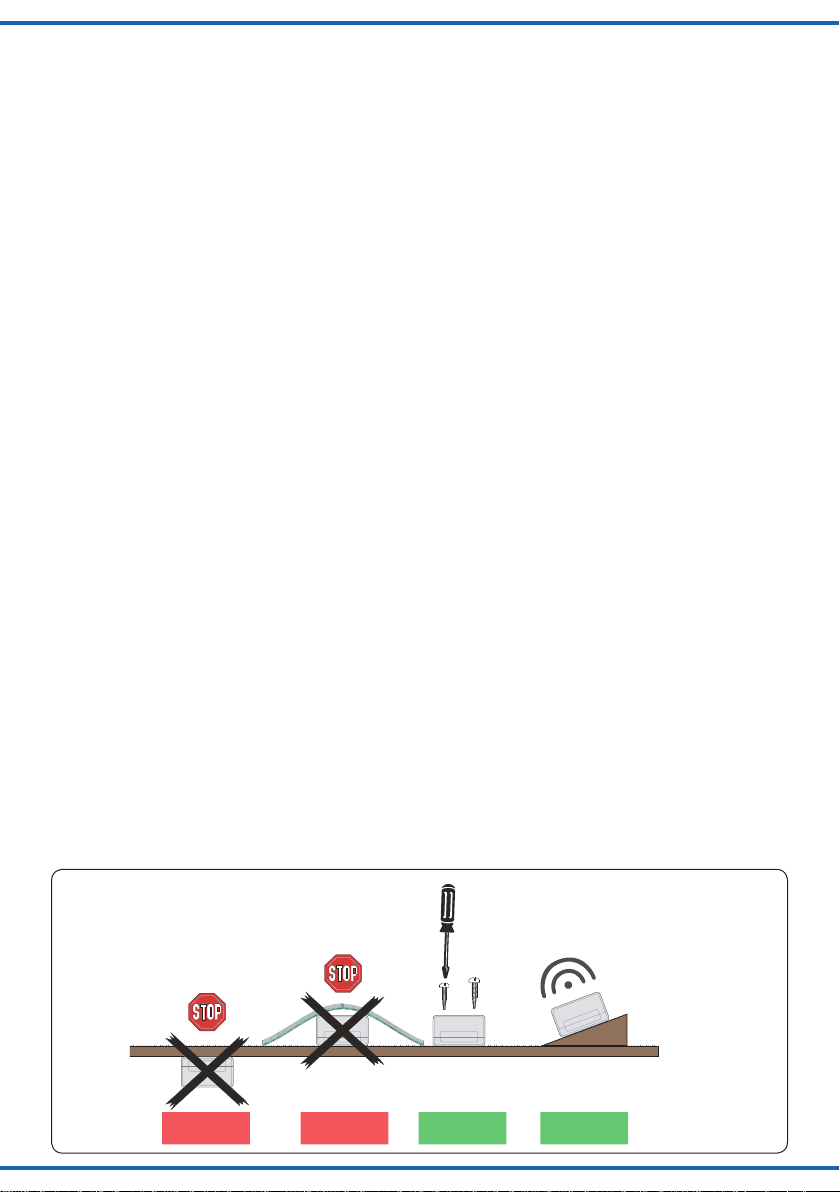
4. Montage
Die Befestigung des Bausteins erfolgt mit den beiliegenden Schrauben. Für optimalen Klang beachten Sie folgende Hinweise:
1. Der Lautsprecher ist im Modul integriert. Für
eine gute Schallverteilung darf die Oberseite
des Moduls nicht verdeckt sein.
2.SoundmodulmöglichstinRichtungderZu-
schauer / Zuhörer ausrichten, also keine ÜberKopf-Montage unter der Anlage.
3.DasSoundmodulsolltesichdortbenden,wo
die entsprechenden Geräusche auf Ihrer Anlage natürlicherweise vorkommen. Sie können
das Modul auch auf der Anlage (z. B. in einem
Gebäude etc.) einbauen. So erreichen Sie
noch besseren Klang und eine bessere Übereinstimmung von sichtbarer und hörbarer Geräuschquelle.
Abb. 1
Einbaulage für Soundmodule
Mounting of Soundmodules
4. Mounting
You x the module by means of the enclosed
screws. To ensure an optimal sound reproduction
of the module, please note the following tips:
1. The loud speaker is an integral part of the module. The upper surface of the module must always be uncovered in order to enable a good
sound dispersion.
2. The sound module must always be adjusted to
the direction of the spectator, so please no upside down mounting under the layout.
3. The sound module should be installed in the
near of the respective scenes on your layout.
You can install the module on the layout itself,
e.g. in a building. This way you can even have
a better sound and an optimal concordance between the visible and the audible sound source.
Lautsprecherschlitze nicht abdecken!
Mit Lautsprecher nach oben montieren!
Don’t cover loudspeaker slots!
Mount the module with loudspeaker on top!
Fig. 1
Falsch RichtigFalsch
wrong correctwrong
Optimal
correct
3
Page 4

5. Anschluss
Die Betriebsspannung des Soundmoduls
beträgt 14 – 16 V = / ~.
Anschluss- und Montagearbeiten nur bei
abgeschalteter Betriebsspannung durchführen!
Nur nach VDE / EN-gefertigte Modellbahntransformatoren verwenden!
Geeignete Kabel: Der geringe Strombedarf des
Soundmoduls erlaubt es, entsprechend klein dimensionierte Kabel, die sich gut versteckt verlegen lassen, zu verwenden. Wir empfehlen Litze
mit einem Querschnitt von 0,14 mm² (z. B. Viess-
mann Art. Nr. 6860 – 6869 oder 68603 – 68693).
Anschluss an Stromversorgung
Das Soundmodul verfügt nicht über einen EinAus-Schalter. Wenn Sie das Soundmodul ausschalten bzw. von der Stromversorgung trennen
möchten, bauen Sie in eine der beiden Stromversorgungsleitungen (braun oder gelb) einen Schalter ein (s. Abb. 2).
Beachten Sie die Sicherheitshinweise oben.
Schließen Sie das Soundmodul gemäß Abbildung
2 an die Stromversorgung an.
5. Connection
The operating voltage of the sound module is
14 – 16 V AC / DC.
All mounting and connection works must
only be executed after the power supply is
cut off.
Only use model railway transformers build
according to VDE / EN!
Fitting cables: due to the low electricity requirements of the sound module you can use thin
cables which can be hidden easily. We recom-
mend to take a ex with a diameter of 0,14 mm²
(e.g. Viessmann ref.-nr. 6860 – 6869 or 68603 –
68693).
Connection to a power supply
The sound module has no on/off-switch. In case
you want to switch off / disconnect from power
supply, the sound module independently you can
incorporate a switch in one of the two power supply wires (brown or yellow), see Illustration 2).
Note the safety measures mentioned above.
Connect the sound module to the power supply
accordingly to the illustration 2.
Abb. 2
z. B. 5200
e. g. 5200
230 V~
Primär
Nur für trockene Räume
Lichttransformator
Primär 230 V 50 - 60 Hz
Sekundär max. 3,25 A52 VA
ta 25°CIP 40
Gefertigt nach
VDE 0570
EN 61558
5200
0-10-16 V~
Sekundär
16 V
10 V
0 V
/ yellow
gelb
braun
Abweichender Anschluss bei den Soundmodulen 5556, 5557 und 5559. Beachten Sie die
AnschlussgrakenindenZusatzanleitungen.
4
z. B. 5570
e. g. 5570
/ brown
Fig. 2
55xx
/ green
Synchron-
eingang
intern / extern
5550
z. B. 5550
e. g. 5550
Synchron-
ausgang
viessmann
Soundmodul
14-16V
~ / =
grün
Universal Ein-Aus-Umschalter
viessmann
The connection of sound modules 5556, 5557
and 5559 is different. Observe the connection
schemes in the supplementary manuals.
Page 5

Anschluss des Synchroneingangs
(nur Art. 5570, 5572, 5554)
Dieses Kapitel beschreibt den Anschluss geeigneter eMotion-Artikel mit Steuerausgang für bewegungssynchronen Sound an Soundmodule mit
entsprechendem Eingang.
Hinweis: Einen optimalen Effekt erreichen
Sie, wenn sich der geräuschauslösende eMotion-Artikel und das Soundmodul in unmittel-
barerNähezueinanderbenden.
►SchaltenSiedieStromversorgungdeseMoti-
on-Artikels und des Soundmoduls aus.
►VerbindenSiediebeidenschwarzenSteuer-
leitungen des eMotion-Artikels mit den beiden
Synchroneingangsbuchsen des Soundmoduls
(siehe Abbildung 3).
Connection of the synchronized input
(only ref.-nr. 5570, 5572, 5554)
This chapter describes how to connect an appropriate eMotion-article equipped with a control
output for motion synchronized sounds to sound
modules with correlative input.
Tip: you get the most efcient effect if you
place the soundless eMotion-article and the
sound module the closest together as possible.
► Switch off the power supply of the eMotion-arti-
cle and of the sound module.
► Connect the two black control wires of the eMo-
tion- article to the two synchronized input con-
nection jacks of the sound module (see illustration 3).
Abb. 3
Achtung: Immer zuerst
die beiden Steuerleitungen
anschließen, um Kurzschluss zu vermeiden.
z. B. 5200
e. g. 5200
230 V~
Primär
Nur für trockene Räume
Lichttransformator
Primär 230 V 50 - 60 Hz
Sekundär max. 3,25 A52 VA
ta 25°CIP 40
Gefertigt nach
VDE 0570
EN 61558
5200
0-10-16 V~
Sekundär
16 V
10 V
0 V
gelb
/ yellow
braun
z. B. 5570
e. g. 5570
/ brown
viessmann
Soundmodul
14-16V
~ / =
Universal Ein-Aus-Umschalter
viessmann
Anschluss des Synchronausgangs
(nur Art. Nr. 5556, 5557, 5573)
Dieses Kapitel beschreibt den Anschluss der
Soundmodule 5556, 5557 und 5573. Bei diesen
Soundmodulen steuert das Modul das Modell. Beachten Sie bitte die Zusatzanleitungen und die folgenden Besonderheiten beim Anschluss sowie –
für Modul 5557 – die Abbildung 4.
5556 / 5557: Zum Ein- und Ausschalten des Modells sowie des Soundmoduls benötigen Sie einen
Caution: Connect at rst
Fig. 3
the control wires (black)
to avoid short circuit.
Synchron-
eingang
55xx
intern / extern
grün
/ green
5550
schwarz
black
z. B. 5115
e. g. 5115
Connection of the synchronized output
(only ref.-nr. 5556, 5557, 5573)
This chapter describes the connection of the
sound modules 5556, 5557 and 5573. In case of
these sound modules, the module itself controls
the functional model. Therefore it is necessary to
respect the supplementary manuals, the following
specic features and the corresponding illustration
4 (for 5557) when executing the interconnection.
5556 / 5557: You need a switch to switch on/
off the model as well as the sound module. The
5
Page 6

Sekundär
0-10-16 V~
16 V
Primär
230 V~
Gefertigt nach
VDE 0570
EN 61558
Lichttransformator
5200
Nur für trockene Räume
Primär 230 V 50 - 60 Hz
Sekundär max. 3,25 A52 VA
ta 25°CIP 40
10 V
0 V
viessmann
5550
Universal Ein-Aus-Umschalter
viessmann
Soundmodul
Synchron-
eingang
14-16V
~ / =
55xx
intern / extern
Synchron-
ausgang
gelb
braun
z. B. 5200
z. B. 5164
grün
5557
schwarz
z. B. 5550
Gleichspannungsbetrieb:
Synchroneingang mit Pol der
Spannungsquelle verbinden.
Synchroneingang mit Pol der
Spannungsquelle verbinden.
/ brown
e. g. 5200
/ yellow
e. g. 5164
/ green
black
e. g. 5550
DC operation:
Connect “Synchroneingang” to
pole of the power supply.
Connect “Synchroneingang” to
pole of the power supply.
Schalter, der an den Buchsen „Synchroneingang“
angeschlossen ist. Viessmannempehlthierzu
den Ein-Aus-Umschalter 5550.
Hinweis: Einen optimalen Effekt erreichen
Sie, wenn sich das Modell und das Soundmo-
dulnahbeieinanderbenden.
switch is connected to the connection jacks “synchronous input”. Viessmann recommends the on/
off commutator 5550.
Tip: you get the most efcient effect if you
place model and sound module the closest together as possible.
Abb. 4
Anschluss eines externen Lautsprechers
Das Soundmodul verfügt über einen Ausgang für
einen externen Lautsprecher mit den elektrischen
Werten mind. 8 Ohm Impedanz und mind. 1/2
Watt Leistung (erhältlich im Elektronik-Fachhandel). Bei Anschluss eines externen Lautsprechers
wird der eingebaute Lautsprecher ausgeschaltet.
1. ZiehenSiedaskurzeamSoundmodulbend-
liche Kabel aus der Buchse rechts daneben.
2. IsolierenSiedaskurzeamSoundmodulbend-
liche Kabel, so dass es keinen Kontakt mit anderen Kabeln haben kann.
3. Montieren Sie den externen Lautsprecher am
vorgesehenen Einbauort.
4. Verlegen Sie die beiden Anschlussleitungen
des externen Lautsprechers zum Soundmodul.
5. Verbinden Sie die Anschlussleitungen mit den
beiden Buchsen gemäß Abbildung 5.
Zum Anschluss eignen sich Stecker und Muffen
wie beispielsweise die Viessmann Artikel 6875
(Stecker orange) und 6884 (Muffe orange).
6
Connection of an external loud speaker
The sound module is equipped with an output for
an external loud speaker with electrical values of 8
Ohm impedance at least and 1/2 watt power (can
be purchased in an electronics-specialized trade).
In case you connect an external loud speaker the
incorporated loud speaker will be switched off.
1. Pull out the short cable to be found at the mod-
2. Insulate the short cable to be found at the mod-
3. Mount the external loud speaker at the place
ule out of the jack to the right of it.
ule so that it cannot have any contact to other
cables.
intended therefore.
4. Lay the two connection wires of the external
loud speaker to the sound module.
5. Connect the two connection wires to the two
connection jacks accordingly to illustration 5.
You can use plugs and sockets for the interconnection, e.g. Viessmann articles 6875 (plug orange) and 6884 (socket orange).
Fig. 4
Page 7

Sekundär
16 V ~
Primär
230 V ~
Gefertigt nach
VDE 0551
EN 60742
Lichttransformator
5200
Nur für trockene Räume
Primär 50/60 Hz230 V
Sekundär max. 3,25 A52 VA
ta 25°CIP 40
viessmann
5550
Universal Ein-Aus-Umschalter
viessmann
Soundmodul
Synchron-
eingang
14-16V
~ / =
55xx
intern / extern
Synchron-
ausgang
orange
z. B. 5570
isolieren
Lautsprecher
(mind. 8 Ω)
/ orange
e. g. 5570
/ isolate
Loudspeaker
(min. 8 Ω)
Abb. 5
Fig. 5
6. Betrieb
Das Soundmodul spielt nach Einschalten der
Stromversorgung die enthaltene Geräuschkulisse in einer Schleife bzw. bewegungssynchron und
kontinuierlich ab (Ausnahme: 5556, 5557, 5559).
Soundmodule mit Synchronausgang steuern das
Modell. Schalten Sie diese mittels des Ein-AusSchalters jeweils an oder aus. Bei Soundmodulen mit Synchroneingang steuern die Modelle das
Soundmodul. Hierbei ist ein Schalter nicht erforderlich (siehe auch Kapitel „Anschluss“).
5556 – 5557 – 5559
Zur Wiedergabe der Sounds ist ein einmaliger
Impuls auf dem Synchroneingang erforderlich.
Danach spielt das Modul auch ohne angeschlossenes Funktionsmodell eine Soundschleife.
Lautstärke einstellen
Sie können die Wiedergabelautstärke des Soundmoduls einstellen. Diese Einstellung gilt sowohl
für den eingebauten als auch für einen alternativ
vorhandenen externen Lautsprecher.
Zum Einstellen der Lautstärke verwenden Sie bitte einen geeigneten Schraubendreher (Schlitz)
wie in Abbildung 6 gezeigt:
►Lauter:
Drehen Sie das Potenziometer nach rechts.
►Leiser:
Drehen Sie das Potenziometer nach links.
6. Operation
If the power supply is switched on the sound
module will play its integrated background noise
continuously either in a loop or synchronous to the
movements (except 5556, 5557, 5559).
Sound modules equipped with a synchronized
output, control the functional model. Switch them
either on or off by means of the on/off switch.
Sound modules equipped with a synchronized
input are controlled by the models. A switch is not
necessary in this case (see also chapter “connection”, page 4).
5556 – 5557 – 5559
To play a sound, one pulse to the sync input is
needed. Once a pulse is set, the sound module
plays the sound even without a connected eMotion model.
Volume adjustment
The sound module is equipped with a volume control for the sound. The adjustment is valid as well
for the integral loud speaker as for an external
loud speaker
To adjust the volume, use a screwdriver (-) and
proceed as following (see g. 6):
► Increase volume:
turn the poti to the right
► Reduce volume:
turn the poti to the left
7
Page 8

viessmann
Soundmodul
Synchron-
eingang
14-16V
~ / =
55xx
intern / extern
Synchron-
ausgang
Abb. 6
Fig. 6
Kleinen Schraubendreher benutzen!
Use a small screwdriver!
7. Fehlersuche und Abhilfe
Jedes Viessmann-Produkt wird unter hohen Qualitätsstandards gefertigt und vor seiner Auslieferung geprüft. Sollte es dennoch zu einer Störung
kommen, prüfen Sie bitte als Erstes die Stromzuführungen und die Verkabelung.
Sollte das Produkt beschädigt sein, geben Sie es
in der zugehörigen Verpackung zu Ihrem Fachhändler oder senden Sie es direkt an den
Viessmann-Service (Adresse siehe unten).
8. Umweltschutzhinweis
Dieses Produkt darf am Ende seiner Lebensdauer
nicht über den normalen Hausmüll entsorgt werden.EsmussaneinemSammelpunktfürdasRecycling von elektrischen und elektronischen Geräten abgegeben werden. Das Mülleimer-Symbol
auf dem Produkt, der Bedienungsanleitung oder
der Verpackung weist darauf hin. Die Werkstoffe
sind gemäß ihrer Kennzeichnung wiederverwertbar.
9. Technische Daten
Maße: 88 x 53 x 22 mm
Gewicht: ca. 50 g
Betriebsspannung: 14 – 16 V ~/=
Betriebsstrom: ca. 150 mA
Schutzklasse / Isolation: IP20
Temperatur / Feuchtigkeit (Betrieb): 0 – 40 °C
Temperatur / Feuchtigkeit (Lager): -10 – 60 °C
7. Troubleshooting and help
Every Viessmann product is produced with high
quality standard and controlled before delivery.
If there should occur any trouble nevertheless,
please check rst the power supply and the wiring.
If the product is damaged, put it in the original
packaging and bring it to your specialist dealer or
send it directly to the Viessmann-service (for the
address see down below).
8. Environmental Care
At the end of life this product is not to be disposed
of as household garbage but has to be returned to
a collection point for the recycling of electrical and
electronic products.
The symbol of the garbage bin on the product, the
manual and the package serves as a reminder. All
materials can be recycled as indicated.
9. Technical Data
Dimensions: 88 x 53 x 22 mm
Weight: approx. 50 g
Operation voltage: 14 – 16 V AC / DC
Operation current: approx. 150 mA
Insulation: IP20
Temperatur / humidity (operation): 0 – 40 °C
Temperatur / humidity (storage): -10 – 60 °C
Modellbauartikel, kein Spielzeug! Nicht geeignet für Kinder unter
14 Jahren! Die Anschlussdrähte niemals in eine Steckdose einführen!
Anleitung aufbewahren!
Model building item, not a toy! Not suitable for children under 14
years! Never put the connecting wires into a power socket! Keep
these instructions!
Ceci n’est pas un jouet. Ne convient pas aux enfants de moins de
14ans!Nejamaisintroduirelesls d’alimentationdansuneprise!
Conservezcemoded’emploi!
8
Modelbouwartikel, geen speelgoed! Niet geschikt voor kinderen
onder 14 jaar! De aansluitdraden nooit in een wandcontactdoos steken!
Gebruiksaanwijzing bewaren!
Articolo di modellismo, non è un giocattolo! Non adatto a bambini
al di sotto dei 14 anni! Non inserire mai i fili di collegamento in una
presa!Conservareinstruzioniperl’uso!
Artículo para modelismo ¡No es un juguete! No recomendado para
menores de 14 años! ¡No introducir nunca los hilos de conexiones en
un enchufe de la red eléctrica! Conserva las instrucciones de servicio!
5/2012 Ko
Stand 02
Sach-Nr. 86143
Made in Europe
 Loading...