

Page 1
Gebrauchsanleitung
Manual
Manual
5268
ServoControl
ServoControl
1. Wichtige Hinweise ...................................... 2
2. Einleitung ................................................... 2
3. Anschlusshinweise ..................................... 2
4. Bedienung .................................................. 2
5. Fehlersuche ............................................... 4
6. Technische Daten ...................................... 4
1. Important Information ................................. 2
2. Introduction ................................................ 2
3. Connections / wiring ................................... 2
4. Operating instructions ................................ 2
5. Troubleshooting ......................................... 4
6. Technical Data ........................................... 4
5268
Page 2
2
D GB
1. Wichtige Hinweise
Lesen Sie vor der ersten Benutzung des Produktes bzw. dessen Einbau diese Anleitung komplett
und aufmerksam durch. Bewahren Sie diese Anleitung auf. Sie ist Teil des Produktes.
Das Produkt richtig verwenden
Das Produkt darf ausschließlich dieser Anleitung
gemäß verwendet werden. Dieses Steuermodul
ist bestimmt
– zum Einbau in Modelleisenbahnanlagen,
– zum Betrieb an einem zugelassenen Modell-
bahntransformator bzw. an einer damit ver-
sorgten elektrischen Steuerung,
– zum Betrieb in trockenen Räumen.
Jeder darüber hinausgehende Gebrauch gilt als
nicht bestimmungsgemäß. Für daraus resultierende Schäden haftet der Hersteller nicht.
2. Einleitung
Mit dem Viessmann ServoControl steuern Sie
Servo-Motoren wie z. B. Viessmann 4552 ganz
bequem von Hand oder automatisch. An jedes
ServoControl-Modul können Sie einen Servo-Antrieb einfach per Steckverbindung anschließen.
Die Ansteuerung ist über Schalter wie z. B. den
Ein-Aus-Umschalter 5550 oder im Digitalbetrieb
über Schaltdecoder wie z. B. 5209 (DCC) oder
5213 (Motorola) möglich.
3. Anschlusshinweise
Alle Anschluss- und Montagearbeiten dürfen
nur bei abgeschalteter Betriebsspannung
durchgeführt werden!
Verwenden Sie nur nach VDE /EN-gefertigte
Modellbahntransformatoren!
Sichern Sie die Stromquellen unbedingt so
ab, dass es bei einem Kurzschluss nicht
zum Kabelbrand kommen kann.
Die Betriebsspannung beträgt 10 - 16 V =/~
an den Eingängen bn (braun) und ge (gelb).
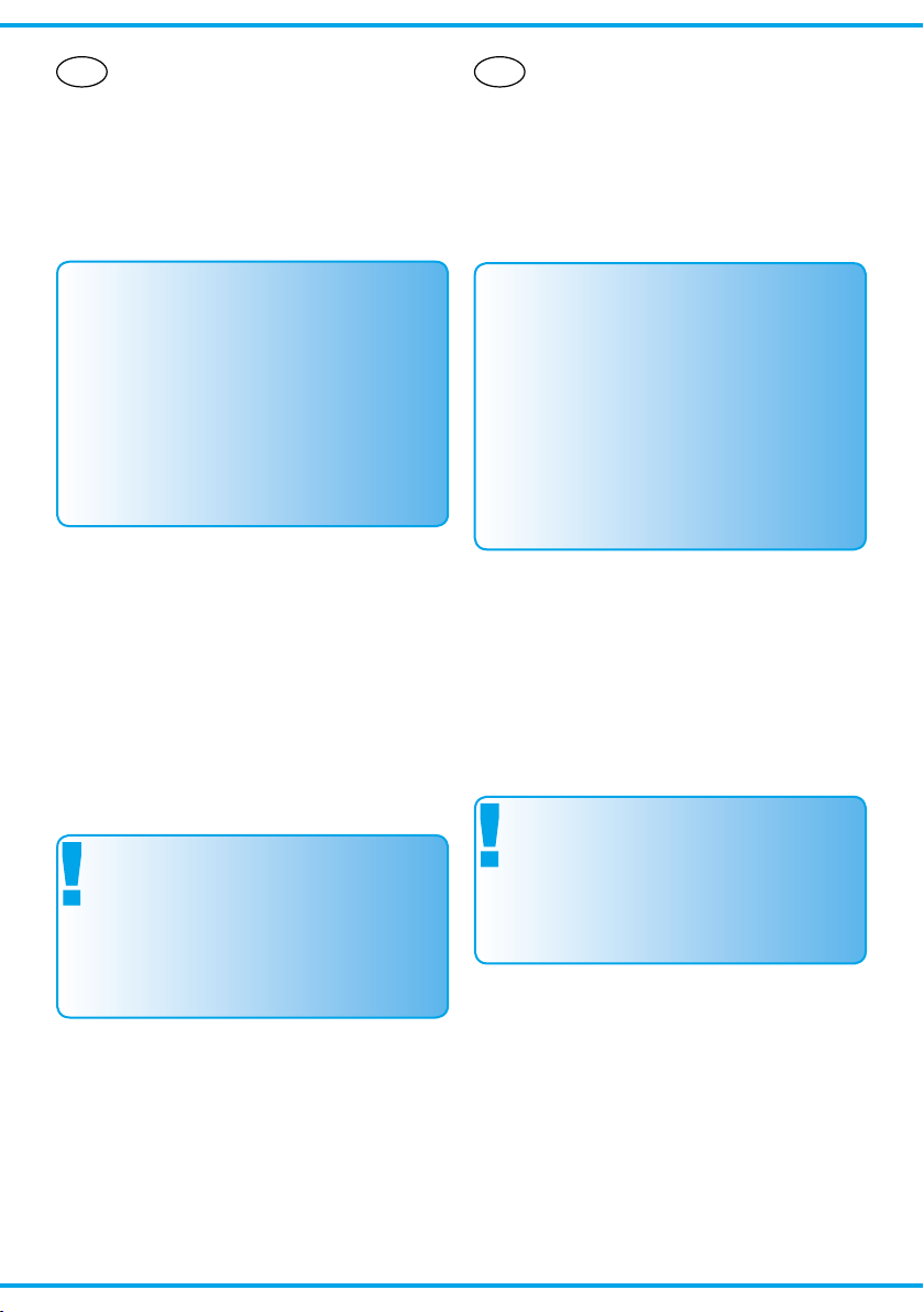
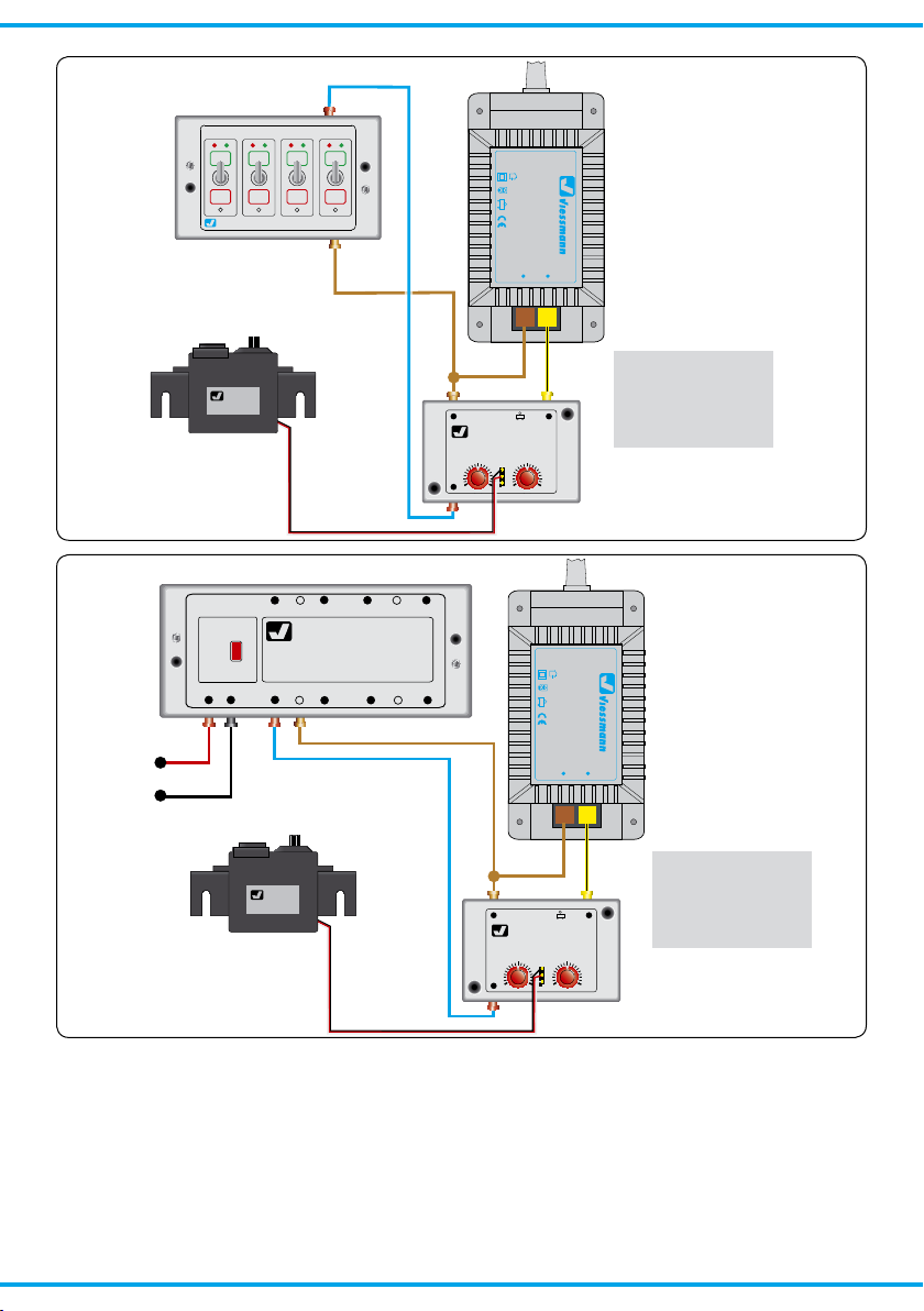
Schließen Sie den ServoControl gemäß den
Abbildungen 1 (analog) oder 2 (digital) an.
4. Bedienung
• SchließenSiedenSchalter„rechts“undstellen
Sie den rechten Anschlag mit P1 ein (Abb. 3).
• ÖffnenSiedenSchalterwieder.
1. Important Information
Please read this manual prior to rst use of the
product resp. its installation! Keep this manual.
It is part of the product.
Using the product
for it’s correct purpose
This product must only be used as required in
this manual. This control module is intended
– for installation in model railroad layouts,
– for connection to an authorized model railroad
transformer or an electrical control system connected to one,
– for operation in a dry area.
Using the product for any other purpose is not
approved and is considered incorrect.
The manufacturer cannot be held responsible for
any damage resulting from the improper use of
this product.
2. Introduction
The Viessmann ServoControl allows you to control easily servo-drives like the Viessmann 4552.
The ServoControl can be connected with a switch
(e. g. 5550) for manual control or with a switch-decoder (e. g. 5209 or 5213) for digital use.
For each servo-drive you need one ServoControl.
3. Connections / wiring
Make sure that the power supply is switched
off when you mount the device and connect
the wires!
Only use VDE/EN tested special model train
transformers for the power supply!
The power sources must be protected to prevent the risk of burning wires.
The operating voltage is 10 - 16 V AC / DC
at the inputs bn (brown) and ge (yellow).
Now make the electrical connection of the Servo-
Control as per gures 1 (analogue) or 2 (digital).
4. Operating instructions
Setup
• Close the switch “rechts” and set up the right
end-position with P1 (see g. 3).
• Open the switch again.
Page 3
3
Sekundär
16 V ~
Primär
230 V ~
Gefertigt nach
VDE 0551
EN 60742
Lichttransformator
5200
Nur für trockene Räume
Primär 50/60 Hz230 V
Sekundär max. 3,25 A52 VA
ta 25°CIP 40
viessmann
ServoControl
5268
ge10 - 16 V~bn
rechts
Drehwinkel rechter Anschlag
Viessmann
ServoAntrieb 4552
viessmann
5550
Universal Ein-Aus-Umschalter
5268
z. B. 5200
z. B. 5550
z. B. 4552
Servo-Kabel
blau
braun
gelb
Gleichstrombetrieb:
braun = minus
gelb = plus
5268
e. g. 5550
e. g. 5200
e. g. 4552
servo-cable
blue
brown
yellow
Power-Supply with DC:
brown = minus
yellow = plus
Sekundär
16 V ~
Primär
230 V ~
Gefertigt nach
VDE 0551
EN 60742
Lichttransformator
5200
Nur für trockene Räume
Primär 50/60 Hz230 V
Sekundär max. 3,25 A52 VA
ta 25°CIP 40
DCCSchaltdecoder
5209
Viessmann
Adresse
–
–
+
+
–
–
+
+
J K 1 gnrt
4 3
2 gnrt
gnrtgn rt
viessmann
ServoControl
5268
ge10 - 16 V~bn
rechts
Drehwinkel rechter Anschlag
Viessmann
ServoAntrieb 4552
5268
z. B. 5200
z. B. 5209
Digitalzentrale
z. B. 4552
Servo-Kabel
blau
braun
gelb
rot
schwarz
Gleichstrombetrieb:
braun = minus
gelb = plus
5268
/ e. g. 5209
e. g. 5200
e. g. 4552
servo-cable
/ blue
/ brown
yellow
red
black
Power-Supply with DC:
brown = minus
yellow = plus
Fig. 1Abb. 1
Fig. 2Abb. 2
• StellenSiedenlinkenAnschlagmitP2(Drehwinkel) ein. Wird danach der rechte Anschlag
verstellt, so verschiebt sich auch der linke
Anschlag entsprechend.
Überlastsicherung
Verwenden Sie möglichst den mittleren Drehbereich des Servos. Einige Servos neigen dazu, an
denEndbereichenzu„wackeln“.Dadurchkom-
• Set the left end-position with P2 (“Drehwinkel”).
If you change the value of the right end-position
after that, the left end-position will change too.
Overload protection
The 5268 is equipped with an overload protection.
If this protection has switched off the module, you
have to switch off the power supply for about 5 10 seconds. After that, the module will work again.
Page 4
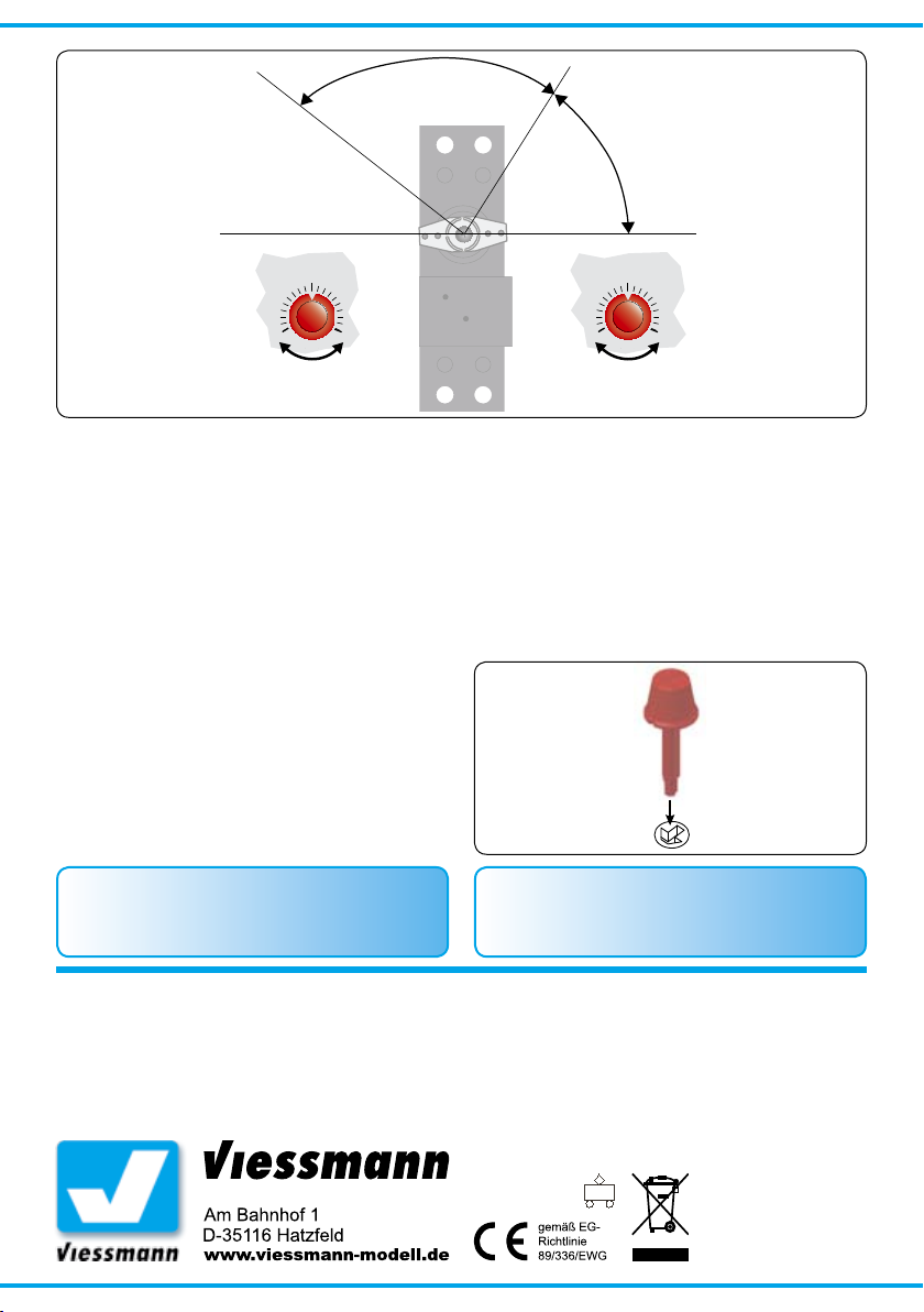
Fig. 3Abb. 3
rechter AnschlagDrehwinkel
z. B. 4552
P 2:
Drehwinkel
P 1:
rechter Anschlag
rechter Anschlag
linker Anschlag
P 1P 2
turn angle
e. g. 4552
right end-point
left end-point
right end-point
men sie nicht zur Ruhe und die Überlastsicherung
des 5268 schaltet das Modul ab.
Wenn die Überlastsicherung des 5268 angesprochen hat, so müssen Sie die Betriebsspannung
ca. 5 - 10 Sekunden abschalten, damit die
Sicherung sich wieder erholt.
5. Fehlersuche
Jedes Viessmann-Produkt wird unter hohen Qualitätsstandards gefertigt. Sollte es dennoch zu
einer Störung kommen, nehmen Sie bitte eine erste Prüfung vor. Stellen Sie sicher, dass alle Kabel
richtig verbunden sind und dass die Spannungsversorgung korrekt funktioniert.
Sollte das Produkt beschädigt sein, geben Sie es
in der zugehörigen Verpackung zu Ihrem Fachhändler oder senden Sie es direkt an den
Viessmann-Service (Adresse siehe unten).
6. Technische Daten
Anschluss: 10 - 16 V =/~
Abmessungen: 54,5 mm x 34,5 mm x 22,5 mm
Dieses Produkt ist kein Spielzeug. Nicht geeignet für
Kinder unter 14 Jahren! Anleitung aufbewahren!
This product is not a toy. Not suitable for children
under 14 years! Keep these instructions!
Ce produit n’est pas un jouet. Ne convient pas aux
enfants de moins de 14 ans ! Conservez ce mode
d’emploi !
5. Troubleshooting
Every Viessmann-product is manufactured under
high quality standards and is tested before delivery. If there is a fault nevertheless, please check
the power supply and the cable connections.
If the product is damaged, send it in the original
package directly for repair to your local dealer or
to the Viessmann company (see below for
address).
Abb. 4
Stecken Sie vorsichtig mit leichtem Druck die
roten Drehknöpfe
gemäß Abb. in
die Schlitze der
Put the red knobs
carefully with light
pressure into the
slots of the potis
as shown in the
gure.
Fig. 4
Einstellregler.
6. Technical Data
Connection: 10 - 16 V AC / DC
Dimensions: 54,5 mm x 34,5 mm x 22,5 mm
Dit produkt is geen speelgoed. Niet geschikt voor kinderen onder 14 jaar! Gebruiksaanwijzing bewaren!
Questo prodotto non è un giocattolo. Non adatto a
bambini al di sotto dei 14 anni! Conservare instruzioni per l’uso!
Esto no es un juguete. No recomendado para menores
de 14 años! Conserva las instrucciones de servicio!
Modellspielwaren GmbH
4
08/2006 Bau
1/2008 Ko
Stand 03
Stand 01
Sach-Nr. 98477
Sach-Nr. 92012
Made in Europe
Made in Europe
 Loading...