

Page 1
Gebrauchsanleitung
Manual
5229
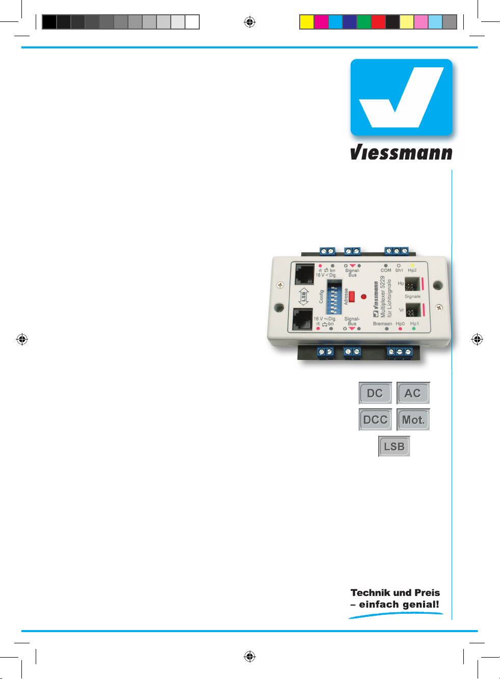
Multiplexer
für Lichtsignale mit Multiplex-Technologie
Multiplexer
for daylight signals
with multiplex-technology
1. Wichtige Hinweise ...................................... 2
2. Einführung / Eigenschaften ........................ 2
3. Anschluss ................................................... 3
4. Kon guration .............................................. 6
5. Signalbus ................................................... 10
6. Signal-Logik ............................................... 11
7. Technische Daten ...................................... 16
1. Important Information ................................. 2
2. Introduction / Properties ............................. 2
3. Connections ............................................... 3
4. Con guration .............................................. 7
5. Signalbus ................................................... 10
6. Signal Logic ............................................... 1 1
7. Technical Data ........................................... 16
5229_92349_01_DE-EN.indd 1 12.09.2008 15:22:16
Page 2
2
DE EN
1. Wichtige Hinweise
Lesen Sie vor der ersten Benutzung des Produktes bzw. dessen Einbau diese Anleitung komplett
und aufmerksam durch. Bewahren Sie diese Anleitung auf. Sie ist Teil des Produktes.
Das Produkt richtig verwenden
Das Produkt darf ausschließlich dieser Anleitung
gemäß verwendet werden. Dieses Steuermodul
ist bestimmt
– zum Einbau in Modelleisenbahnanlagen,
– zum Anschluss an einen zugelassenen Modell-
bahntransformator mit einer Ausgangsspannung von max. 16 V~ bzw. an einer damit versorgten Steuerung (z. B. Viessmann 5200 oder
Viessmann Commander 5300),
– zum Betrieb in trockenen Räumen.
– zur Ansteuerung von Signalen
mit Multiplex-Technologie
Jeder darüber hinausgehende Gebrauch gilt als
nicht bestimmungsgemäß. Für daraus resultierende Schäden haftet der Hersteller nicht.
2. Einführung / Eigenschaften
Der Multiplexer 5229 steuert ein zwei- oder mehrbegrifges Tageslicht-Signal mit dem dazu gehörenden Vorsignal. Das Signal muss mit der Viess-
mann Multiplextechnik ausgestattet sein.
Der Multiplexer kann folgende Signale steuern:
Viessmann Ks-Signale 4040 - 4046 und
Viessmann Lichtsignale 4720 - 4730.
Signalbilder und Adressen nden Sie auf Seite 15.
Der Multiplexer erkennt automatisch den Typ des
angeschlossenen Signals. Er konguriert sich entsprechend automatisch. In Verbindung mit dem
Commander (Anschluss am LSB) kann sich das
Modul auch auf alle weiteren Parameter (z. B. Di-
gitaladressen) automatisch kongurieren, so dass
keine manuellen Einstellungen nötig sind.
Bei Verwendung anderer Digitalzentralen bzw.
im analogen Betrieb werden Optionen über DIPSchalter (s. a. Abb. 4 auf S. 7) und gegebenenfalls
Digitaladressen manuell eingerichtet. Bei diesem
Vorgang werden gleichzeitig die Eigenschaften
des zu steuernden Signals konguriert:
• sofortiges oder weiches Überblenden
der Signalbilder
• gekoppeltes Signal
• Bahnhofs- oder Blocksignal-Logik
• Bremsgenerator ja / nein
1. Important Information
Please read this manual prior to rst use of the
product resp. its installation! Keep this manual. It
is part of the product.
Using the product for it’s correct
purpose
This product must only be used as required in
this manual. This model of a signal is intended
– for installation in model railroad layouts,
– for connection to an authorized model railroad
transformer with an output voltage of max.
16 V~ or an electrical control system connected to one (e. g. Viessmann 5200 or Viessmann
Commander),
– for operation in a dry area.
– for connection to a daylight signal with
multiplex technology
Using the product for any other purpose is not
approved and is considered incorrect. The
manufacturer cannot be held responsible for any
damage resulting from the improper use of this
product.
2. Introduction / Properties
The module 5229 „Multiplexer“ controls a twoaspect or a combined-aspect daylight signal and
the appropriate distant signal. The signal must be
equipped with the Viessmann multiplex-technique.
The Multiplexer can operate the following signals:
Viessmann Ks-signals 4040 – 4046 and
Viessmann light signals 4720 – 4730
For signal aspects and addresses, refer to p. 15.
The Multiplexer identies automatically the type
of the connected signal. The conguration is done
automatically. In case that the module is connected to the Commander (connection to the LSB) it
is also enabled to execute the autoconguration
of all further parameters (e.g. digital address). No
manual adjustment is necessary then.
In combination with other digital command stations respectively with conventional systems, options and digital addresses can be adjusted by
a DIP-switch manually (see illustration Nr. 4 on
page 7). The features of the signal you want to
operate are programmed synchronously:
• immediate and soft fade-over of signal aspects
• coupled signal
• station block- or block signal logic
• brake generator yes/ no
5229_92349_01_DE-EN.indd 2 12.09.2008 15:22:16
Page 3
3
Die einmal eingestellte Konguration und das aktuelle Signalbild werden intern gespeichert und
bei jedem Spielbeginn wieder zurückgeholt.
Vorsignal
Das Steuermodul gibt am Anschluss Vr immer
das Signalbild für ein separat stehendes Vorsignal aus.
Verfügt das Signal am Anschluss Hp über ein Vorsignal am eigenen Mast, dann gehört dieses Vorsignal am Mast zum folgenden Hauptsignal. Es
erhält die erforderlichen Informationen über den
Signalbus und zeigt das entsprechende Signalbild
an. Der Vorsignalbegriff wird über den Signalbus
oder die 3. und 4. Digitaladresse übertragen.
In den Stellungen „Halt“ oder „Rangierverbot aufgehoben“ wird das Vorsignal am eigenen Mast
automatisch dunkel geschaltet. Diese „Dunkeltastung“ entspricht dem Vorbild, denn wer nicht
weiterfahren darf, braucht die Stellung des nächsten Signals nicht zu kennen.
Update
Der Multiplexer 5229 ist aktualisierbar. Eine neue
Version der Software können Sie über den LSB
mit Hilfe des Commander jederzeit selbst auf den
Multiplexer aufspielen. Nähere Informationen nden Sie jeweils in der Anleitung zum Update.
3. Anschluss
Stecken Sie den Signalstecker in die entsprechende Buchse des Multiplexers. Achten Sie auf
die korrekte Polarität. Die Markierung am Stecker
muss mit der Markierung am Multiplexer übereinstimmen.
Bei verpolt eingesteckten Steckern wird nichts beschädigt. Das Signal wird dann allerdings falsch
erkannt und entsprechend falsch angesteuert.
Zum Anschluss des Multiplexers an die Steuerung Ihrer Modellbahn (Stellpulte, Digitalzentrale)
beachten Sie bitte die unten stehenden Hinweise
und Zeichnungen. Schließen Sie den Multiplexer
gemäß den folgenden Abbildungen 1 bis 3 an.
Alle Anschluss- und Montagearbeiten dürfen
nur bei abgeschalteter Betriebsspannung
durchgeführt werden (Ausnahme: LSBAnschuss und Signalanschluss)!
Verwenden Sie nur nach VDE /EN-gefertigte
Modellbahntransformatoren!
Sichern Sie die Stromquellen unbedingt so
ab, dass es bei einem Kurzschluss nicht
zum Kabelbrand kommen kann!
The adjusted conguration and the actual signal
aspect are saved in the module and reactivated at
every new play session.
Distant signal
The connection jack ”Vr” of the module emits always the signal aspect for a separate installed
distant signal.
In case that the signal connected to the output
“Hp” is equipped with a distant signal at its own
post, this distant signal is interconnected with the
proximate main signal. The signal bus transmits
the required information for the appropriate aspect
to the signal. The indication information for the
distant signal is transmitted either by the signalbus or by the 3. and 4. digital address.
In case of a signal aspect showing “Stop, no train
or shunting movement” or ”only shunting movement allowed” the distant signal at the own mast
will be masked automatically. A masked signal
complies the principle of the real railway.: if you
cannot proceed on your journey route, the aspect
of the proximate signal must not be known.
Update
The “Multiplexer 5229” can be updated. You can
download a new software version to the Multiplexer at any time by yourself via the Commander,
using the LSB connection . You will nd further information in the instruction for the update.
3. Connections
Insert the plug of the signal in the respective jack
of the Multiplexer. Please respect the correct po-
larity. The mark on the plug must correspond to
the mark on the Multiplexer.
Connection with wrong polarity does not destroy
anything. But the identication and control of the
signal will be incorrect then.
For connection of the Multiplexer to the control device of your layout (control panels, digital central
station), please refer to the tips and illustrations at
the bottom. Connect the Multiplexer as shown in
the illustrations 1 – 3.
Make sure that the power supply is switched
off when you mount the device and connect
the wires!
Exception: LSB-cables and signal plugs can
be connected, while power is on.
Only use VDE/EN tested special model train
transformers for the power supply!
The power sources must be protected to prevent the risk of burning wires.
5229_92349_01_DE-EN.indd 3 12.09.2008 15:22:16
Page 4
4
viessmann
Multiplexer 5229
für Lichtsignale
ON
1
2
3
4
5
6
7
8
WnP
LSB
Sh1 Hp2
Hp1Hp0
Bremsen
Signal-
Bus
Signal-
Bus
rt bn
16 V ~/ Dig.
16 V ~/ Dig.
rt bn
Hp
Vr
COM
Signale
viessmann
5545
Stellpult für Ausfahrsignale
braun
4 x blau
rot
rot
braun
/ blue
/ brown
/ red
red
red
brown
16 V ~ / =
Fig. 1
Abb. 1
1.
2.
3.
4.
5.
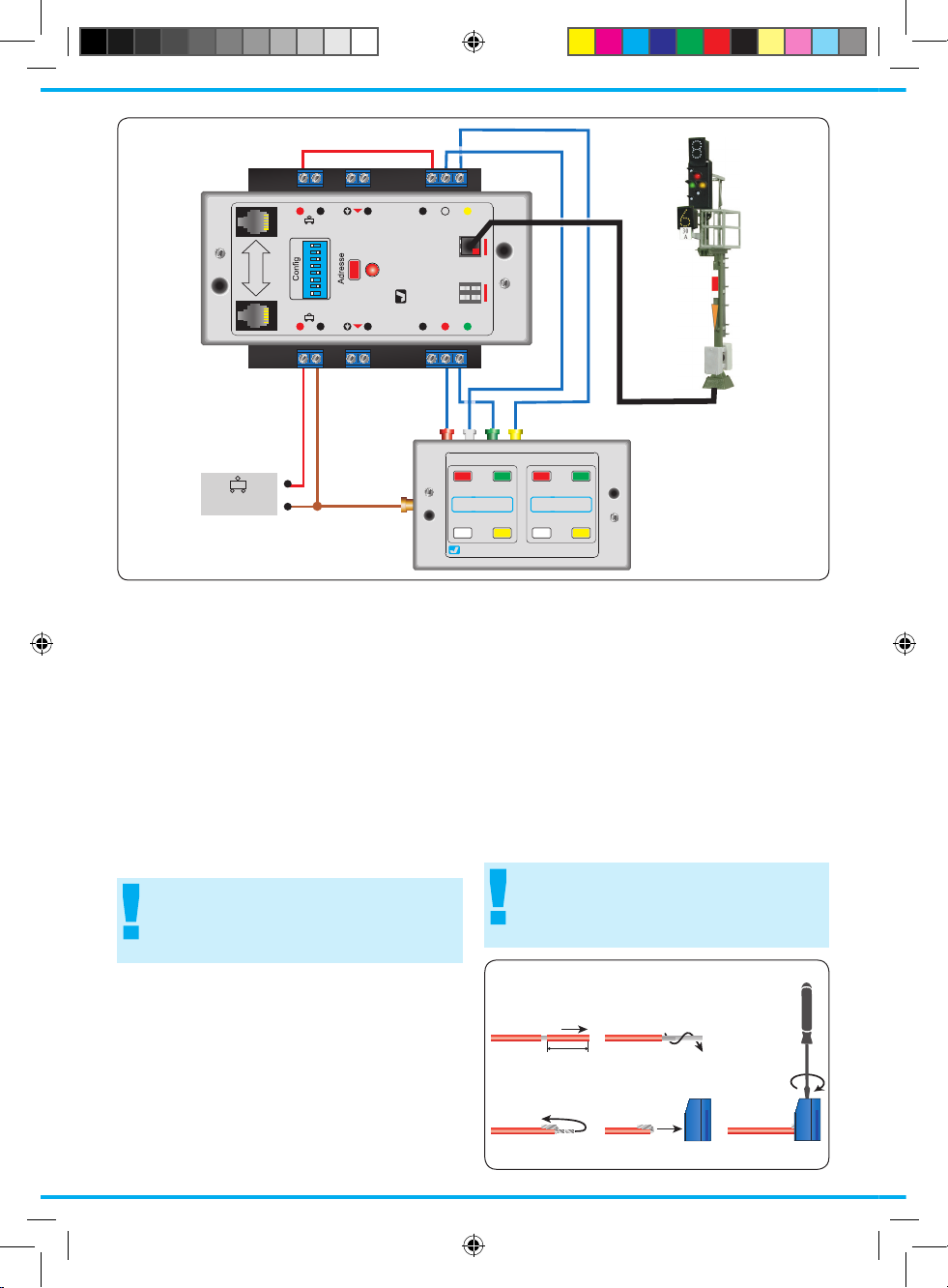
Kabel in Schraubklemme befestigen
Draht einschiebenDraht umbiegen
Litzen verdrillenKabel abisolieren
Schraube festziehen
Insert wire Bend wire
Twist wires togetherStrip the insulation
from the cable
Fix cable in a terminal block
Tighten the screw
5 mm
Konventioneller (analoger) Anschluss
Im konventionellen Betrieb stellen Sie die Signale
mit Hilfe der Viessmann Tasten-Stellpulte 5547
(für 4 zweibegrif ge Signale), 5546 (für 2 dreibegrif ge Signale) und 5545 (für 2 vierbegrif ge Si-
gnale). So entsprechen Tastenfarbe und -anord-
nung dem jeweiligen Signaltyp und dessen Stellmöglichkeiten (Abb. 1 auf Seite 4).
Moderne Ks-Signale haben teilweise mehr als vier
Signalbegriffe. Über Stellpulte lassen sich nur die
vier Begriffe Hp0 (rot), Ks1 (grün), Ks1+Zs3 (gelb)
und Hp0+Sh1 (weiß) schalten.
Hinweis Gleichstrombetrieb:
Beachten Sie beim Betrieb mit Gleichstrom unbedingt die Polarität:
rot = Plus, braun = Minus
Digitaler Anschluss (am Gleis)
Beim Digitalbetrieb verbinden Sie die Klemmen
„rt“ und „bn“ mit dem Gleisausgang einer Digitalzentrale oder eines Boosters (Abb. 2 auf Seite 5).
Parallel zu einer Digitalzentrale können Sie ein ex-
ternes Tastenstellpult an den Multiplexer anschließen und so das Signal auch von Hand steuern.
Allerdings wird in diesem Fall die Stellinformation
nicht an die Digitalzentrale weitergegeben.
Connection to conventional systems
Signals working in a conventional system can
be operated by the Viessmann pushbutton panels 5547 ( for 4 two-aspect signals), 5546 ( for 2
three-aspect signals) and 5545 (for 2 four-aspect
signals). Colour and grouping of the pushbuttons
thus correspond to the switching possibilities of
the respective signal type (see g. 1 on p. 4).
Modern Ks signals have sometimes more then 4
aspects. Control panels can only switch over to
the following four aspects: Hp0 (red), Ks1 (green),
Ks1+Zs3 (yellow) and Hp0+ Sh1 (white).
Tip for direct current operating:
Please respect absolutely the polarity,
when operating with direct current.
Red = plus, brown = minus
5229_92349_01_DE-EN.indd 4 12.09.2008 15:22:17
Page 5
5
viessmann
Multiplexer 5229
für Lichtsignale
ON
1
2
3
4
5
6
7
8
WnP
LSB
Sh1 Hp2
Hp1Hp0
Bremsen
Signal-
Bus
Signal-
Bus
rt bn
16 V ~/ Dig.
16 V ~/ Dig.
rt bn
Hp
Vr
COM
Signale
Commander
braun
rot
rotrotrot
z. B.
Spannung
mind. 15 V bei Verwendung von 5228.
brown
red
red
e. g.
/ Voltage
min. 15 V when using 5228.
Mot. / DCC
Digitalzentrale / Booster
Fig. 2
Abb. 2
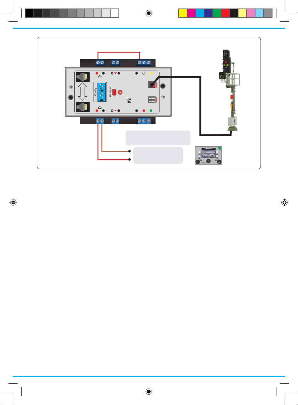
Digitaler Anschluss (am LSB)
Wenn Sie als Digitalzentrale den Commander
verwenden, sollten Sie den Multiplexer über den
leistungsfähigen SpeedBus LSB anschließen
(Abb. 3 auf Seite 6). Nutzen Sie zur Verbindung
von LSB-Geräten bitte unsere speziellen LSB-Kabel (Artikel-Nr. 5390 - 5393). Diese sind mit Steckern konfektioniert und sofort einsetzbar.
Die beiden LSB-Buchsen des Multiplexers sind
parallel geschaltet. Verbinden Sie eine beliebige
Buchse per LSB-Kabel mit dem Commander. An
die andere Buchse können Sie weitere LSB-Ge-
räte anschließen. Die Verbindung zum Commander kann auch indirekt über weitere LSB-Geräte
erfolgen.
Der Multiplexer meldet sich dann automatisch am
Commander an und kon guriert sich selbst (Autokon guration).
Parallel zum Commander können Sie ein externes
Tastenstellpult (Vergleiche Abb. 1) an den Multiplexer anschließen und so das Signal auch von
Hand steuern. Die Stellinformation des Signals
wird über den LSB an den Commander übermittelt. So zeigt auch der integrierte Gleisplan stets
die korrekte Signalstellung und die Automatik des
Commanders kann diese auswerten.
Die vier Stelleingänge des Multiplexers (Hp0,
Hp1, Hp2, Sh1) lassen sich optional als frei kon-
gurierbare Rückmeldekontakte am Commander
verwenden. Die Kon guration erfolgt über den
Commander. Mehr Infos im Referenzhandbuch
des Commanders.
Digital connection to the rail
Using a digital system, you connect the terminals
“rt” and “bn” to the rail output of a digital command
station or of a booster (see g. 2 on page 5).
You can connect an external pushbutton panel
parallel with a digital command station to the Multiplexer in order to operate the signal also manually. But in this case the switching information is
not transmitted to the digital command station.
Digital connection to the LSB
Connect the Multiplexer to the ef cient Speed-
Bus LSB, when using the Commander as digital
command station (see illustration 3 on page 6).
Please, use our special LSB-cables (order number
5390 – 5393) for the interconnection of LSB devices. They are ready made with the correct plugs.
The two LSB connection jacks of the Multiplexer
have a parallel connection. You can insert the LSB
cable in any jack you want in order to connect
the Commander. More LSB-devices can be con-
nected to the second jack. The interconnection to
the Commander can also be effected indirectly by
other connected LSB devices.
The Multiplexer registers itself automatically at the
Commander by autocon guration then.
You can connect an external pushbutton panel
to the Multiplexer, parallel with the Commander,
in order to operate the signal also manually (see
g. 1 on page 4). The switching information of the
signal will be transmitted to the Commander by
5229_92349_01_DE-EN.indd 5 12.09.2008 15:22:17
Page 6

6
viessmann
Multiplexer 5229
für Lichtsignale
ON
1
2
3
4
5
6
7
8
WnP
LSB
Sh1 Hp2
Hp1Hp0
Bremsen
Signal-
Bus
Signal-
Bus
rt bn
16 V ~/ Dig.
16 V ~/ Dig.
rt bn
Hp
Vr
COM
Signale
Commander
braun
gelb
z. B.
5200
/ brown
/ yellow
/ e. g.
LSB
16 V ~ / =
LSB
5390 – 28 cm
5391 – 60 cm
5392 – 215 cm
5393 – 600 cm
Fig. 3
Abb. 3
DIP-Nr. Stellung „Aus“
Position “Off”
Stellung „Ein“
Position “On”
1 direktes Überblenden der Signalbilder
hard switch of signal aspects
weiches Überblenden der Signalbilder
soft dissolve of signal aspects
2 ungekoppeltes Signal
un-coupled signal
gekoppeltes Signal (nur Hp0 und Hp2)
coupled signal (only Hp0 and Hp2)
3 Bahnhofssignallogik
Yard signal logic
Blocksignallogik
Block signal logic
4 kein Bremsgenerator
no brake generator
Bremsgenerator angeschlossen
brake generator connected
5 0 km/h 80 km/h
6 0 km/h 40 km/h
7 0 km/h 20 km/h
8 0 km/h 10 km/h
4. Konfi guration
Nach Anschluss des Multiplexers muss dieser
kon guriert werden. Nur bei Anschluss des Mul-
tiplexers über den LSB an den Commander kann
die Kon guration automatisch erfolgen. Informa-
the LSB. This way the integrated track diagram
always displays the correct signal aspect and the
automatic operating mode of the Commander can
exploit it.
Optionally, the four switching inputs of the multi-
5229_92349_01_DE-EN.indd 6 12.09.2008 15:22:19
Page 7

7
ON
1
2
3
4
5
6
7
8
WnP
DIP-Schalter
Ein
Aus
DIP-Switch
/ On
/ Off
Fig. 4
Abb. 4
tionen zum Anschluss des Multiplexers an den
Commander nden Sie im Referenzhandbuch des
Commanders.
Optionen
Die möglichen Signaloptionen stellen Sie über die
DIP-Schalter („Mäuseklavier“, Abb.4) des Multiplexers ein (siehe Tabelle Seite 6). Die Stellung
des DIP-Schalters wird beim Einschalten des Moduls oder nach einem kurzen Druck auf die Taste
„Adresse“ eingelesen.
Der Multiplexer übernimmt die Einstellungen und
liest das angeschlossene Signal neu ein. Dieses
blinkt während des Erkennungsvorganges kurz
auf.
Hinweis:
Ist der Multiplexer über den LSB mit einem
Commander verbunden, können die Opti-
onen auch über diesen eingestellt werden.
Streckengeschwindigkeit einstellen
Die ab diesem Hauptsignal zulässige Streckengeschwindigkeit – Anzeige über das Zusatzsignal
Zs3 der Viessmann Ks-Signale – stellen Sie über
die DIP-Schalter ein:
Damit das vorhergehende Signal bzw. dessen Modul (5224 oder 5229) über den Signalbus erfährt,
ob es eine Langsamfahrt bzw. eine niedrigere Ge-
schwindigkeit anzeigen soll, muss die jeweils ab
diesem Hauptsignal gültige Streckengeschwindigkeit im Modul eingetragen werden.
Die höchste anzuzeigende Geschwindigkeit beträgt 15 (= 150 km/h). Die höchste zulässige
Geschwindigkeit auf Standardstrecken (Indusi /
PZB90) beträgt 160 km/h und muss nicht per Signal angezeigt werden. Höhere Geschwindigkeiten dürfen nur auf Strecken mit der Zugsiche-
rung LZB gefahren werden. Diese benötigt aber
keine Signalisierung.
Zur Einstellung:
Addieren Sie die Einzelgeschwindigkeiten des
plexer (Hp0, Hp1, Hp2, Sh1) can also be used as
free programmable feedback contacts by the Commander. The Commander executes the congu-
ration. You will nd more information in the reference manual of the Commander.
4. Conguration
The Multiplexer must be congurated after the
connection to a device. An automatic conguration
of the Multiplexer is executed, when connected to
the Commander by the LSB only. You will nd in-
formation about the connection of the Multiplexer
to the Commander in the reference manual of the
Commander.
Options
You can adjust the different signal options by
the DIP-switch of the Multiplexer (see g. 4 and
schedule on page 6). The adjusted position of the
DIP-switch is read when switching on the module
or by a short pressure on the key “address”.
The Multiplexer takes over the adjustments and
registers the connected signal renewed. The
signal is blinking shortly during this recognition
procedure.
Tip:
In case that the Multiplexer is connected to
a Commander by the LSB, the options can
also be adjusted from the Commander.
Adjustment of the line speed
The permissible line speed allowed from this main
signal on – indicated by the supplementary signal
indication Zs3 of the Viessmann Ks signals- can
be adjusted by the DIP switch.
The previous signal respectively its control module
( 5224 or 5229) must get information by the signal
bus, if it has to indicate ”proceed slowly” respectively a lower speed. Therefore the permissible
line speed allowed from this specic main signal
on must be programmed in the control module.
5229_92349_01_DE-EN.indd 7 12.09.2008 15:22:20
Page 8

8
viessmann
Multiplexer 5229
für Lichtsignale
ON
1
2
3
4
5
6
7
8
WnP
LSB
Sh1 Hp2
Hp1Hp0
Bremsen
Signal-
Bus
Signal-
Bus
rt bn
16 V ~/ Dig.
16 V ~/ Dig.
rt bn
Hp
Vr
COM
Signale
Fahrtrichtung / Route
viessmann
5224
Steuermodul für
Lichtsignale
Signal(e)
Sh1COM Hp2
Hp1Hp0
Brem-
sen
Signal-
Bus
Signal-
Bus
rt bn
16 V ~/
Digital
16 V ~/
Digital
rt bn
▼
▼
Hp Vr
1
2
1
2
1
2
braun
rot
grau
lila
Signalbus
Fig. 5
Abb. 5
DIP-Schalters bis zur gewünschten Geschwindig-
keit. Beginnen Sie mit dem größten Wert.
Beispiel: Streckengeschwindigkeit 130 km/h
DIP-Schalter 5 auf „Ein“ = 80 km/h
DIP-Schalter 6 auf „Ein“ = 40 km/h
DIP-Schalter 8 auf „Ein“ = 10 km/h
Digitale Ansteuerung
Das Modul benötigt zur Ansteuerung im Märklin-
Motorola- und im NMRA-DCC-Betrieb bis zu vier
direkt aufeinander folgende Digital-Weichenadres-
sen. Bei einem mehrbegrifgen Signal, das mehr
als eine Adresse benötigt, ist die erste Adresse
immer eine ungerade Adresse.
Bis zu fünf externe Kontakte oder Taster können
angeschlossen werden, über die das Signalmodul
vom Zug aus geschaltet werden kann. Vier für die
Stellungen „rot“, „grün“, „grün/gelb“ und „rangieren“. Der fünfte Anschluss („Bremsen“) ist für den
Bremskontakt, der beim Anschluss eines Bremsgenerators die Umschaltung der Stromversorgung von Fahren (Zentrale/Booster) auf Bremsen
(Bremsgenerator) auslöst. Ohne Bremsgenerator
wird die Fahrstromunterbrechung sofort wirksam,
wenn das Signal auf „Halt“ gestellt wird. Die Ein- /
Ausschaltung bzw. die Umschaltung des Fahrstroms übernimmt das ansteckbare Viessmann
Zugbeeinussungsrelais 5228 (s. a. Anleitung zu
Modul 5228).
The highest speed that is to be indicated is 15 (=
150 km/h). The highest permissible line speed is
160 km/h on a normal line (automatic train control
ATC/ PZB90). It must not be indicated by a signal.
Higher speeds are only allowed on lines equipped
with the continuous train control system LZB. It
requires no special signalling.
The Adjustment
Add up the individual speeds adjustable by the
DIP switch, till you reach the required speed.
Begin with the highest value.
Example: line speed 130 km/h
DIP switch 5 on “on” = 80 km/h
DIP switch 6 on “on” = 40 km/h
DIP switch 8 on “on” = 10 km/h
Digital Mode of the Control Module
The module requires in both Maerklin Motorola
and NMRA DCC format up to four successive ad-
dresses. If two or more addresses are required
(for a multi-aspect signal) the rst one is always
an even number.
Up to ve external contacts or push buttons can
be connected for switching the signal (either
manually or by the train). The rst four are for:
red, green, green-yellow and shunting. The fth
is called “braking” and is intended for the brake
generator and triggers the change over from normal supply from the command station or booster
5229_92349_01_DE-EN.indd 8 12.09.2008 15:22:20
Page 9

9
Digitaladresse (Märklin-Motorola)
Zum Eingeben einer Adresse für das Märklin-Motorola-Format drücken Sie die Taste „Adresse“ solange, bis die rote Kontroll-LED langsam blinkt.
Geben Sie jetzt mit Ihrem Digitalsystem einen
Märklin-Motorola-Stellbefehl mit der Adresse, die
Sie für das Signal vorgesehen haben. Das Modul unterstützt bis zu 320 Motorola-Adressen. Es
speichert den ersten eintreffenden gültigen Weichenstellbefehl als seinen eigenen ab. Als Zeichen dafür erlischt die Kontroll-LED und das Signal führt den Befehl aus.
Digitaladresse (NMRA-DCC)
Zum Eingeben einer Adresse für das DCC-Format drücken Sie die Taste „Adresse“ solange, bis
die rote Kontroll-LED langsam blinkt. Drücken Sie
die Taste kurz erneut um in den DCC-Modus zu
wechseln. Die LED blinkt nun schnell.
Geben Sie jetzt mit Ihrem Digitalsystem einen
DCC-Stellbefehl mit der Adresse, die Sie für das
Signal vorgesehen haben. Das Modul unterstützt
bis zu 2048 DCC-Adressen. Es speichert den ersten eintreffenden gültigen Weichenstellbefehl als
seinen eigenen ab. Als Zeichen dafür erlischt die
Kontroll-LED und das Signal führt den Befehl aus.
Bei der Konguration auf ein mehrbegrifges
Signal übernimmt es eine ungerade DigitalAdresse als erste und die darauf folgende
gerade als zweite. Deshalb würde bei einem
mehrbegrifgen Signal ein Stellbefehl für die
Adresse 001 oder für die Adresse 002 das
Modul in beiden Fällen auf die Adressen
001 und 002 programmieren. Die Kombination der Adressen 002 und 003 ist nicht
möglich, da dies zu Überschneidungen mit
dem Adressbereich anderer Decoder führen
könnte.
Beenden der Adresseinstellung
Mit dem Empfang eines gültigen Digitalbefehls beendet das Steuermodul die Adresseingabe auto-
matisch. Um den Adresseinstellungsmodus ohne
Änderungen zu verlassen, drücken Sie die Taste
„Adresse“ ein drittes Mal.
Werkseinstellung:
Setzen Sie das Modul auf Werkseinstellungen zurück, indem Sie bei gedrückter Taste „Adresse“,
die Betriebsspannung einschalten.
In der Werkseinstellung ist das Modul auf die
Motorola-Adresse 1 und Optionen gemäß der
DIP-Schalter konguriert.
to supply via the brake generator. Without brake
generator the interruption of the track power be-
comes effective immediately if the signal shows
“stop”. The switching of the track power is done by
the Viessmann track sector relay 5228 (see also
manual for 5228).
Programming for Märklin Motorola
To enter an address for maerklin motorola, push
the button “address” until the red control LED
starts to blink (for about 3 seconds). The control
module indicates this status by slow blinking of
the control LED. Now you may enter a command
with the keyboard with the address to be used for
this signal. Up to 320 addresses are possible.
The module waits for the rst valid switch-command and takes its address as its own. The now
dark LED indicates the completion of this process
and the signal shows the appropriate aspect.
Programming for NMRA DCC
To enter an address for DCC, push the button “ad-
dress”, until the red control LED starts to blink. A
second press of the button takes the module to
the DCC programming mode. The LED indicates
this status by fast blinking.
Now you may send a DCC-command. Up to 2048
addresses are possible. The module waits for the
rst valid switch-command and takes its address
as its own. The now dark LED indicates the com-
pletion of this process and the signal shows the
appropriate aspect.
When conguring the module for a multi-
aspect signal the module accepts an uneven
digital address as its rst and the subsequent even number as the second address.
Therefore the command for a multi-aspect
signal for address 001 and 002 would programm the module in both cases to address
001 and 002. The combination of address
002 and 003 is not permitted, since this
could easily lead to overlaps with the address of other decoders.
Finishing the address adjustment
The control module nishes automatically the
programming of the address after the reception
of a valid digital command. If you want to quit the
address programming mode without any change,
press the key “Address” a third time.
Reset:
Push the key “address”, hold it pressed and switch
on the operating voltage. The initial company set-
5229_92349_01_DE-EN.indd 9 12.09.2008 15:22:20
Page 10

10
5. Signalbus
Bei modernen Signalsystemen sind die Einzelsignale voneinander abhängig bzw. das Signalbild eines Signals wird vom folgenden Signal mit
beeinusst. Um diese Abhängigkeiten im Modell
ohne übergeordnete Intelligenz vorbildgerecht
nachbilden zu können, werden die Signale untereinander über den Viessmann-Signalbus verbunden. Der Signalbus ist eine Datenübertragung
über zwei zusätzliche Kabel und arbeitet entgegen der Fahrtrichtung der Züge. Er wird z. B. von
den Modulen 5224 und 5229 unterstützt. Entsprechend können Signale und Module auf der Strecke gemischt aufgestellt werden.
Übertragung der Signalstellung: Der Signalbus
überträgt die Stellung des Signals (die Streckengeschwindigkeit) an das vorhergehende, empfangende Signal. Aus dem eigenen Stellbefehl und
der erhaltenen Information erzeugt dieses Signal
seine eigene Stellung für Haupt- und Vorsignal.
Es passt daraufhin ggf. das Signalbild von Hauptund Vorsignal an. Das empfangende Signal überträgt dann seinerseits die entsprechenden Informationen an das wiederum davor liegende Signal.
Der Signalbus arbeitet sogar zwischen den verschiedenen Signalgenerationen und -typen (z. B
Ks-Signalen und Lichtsignalen der Bauart 69), so
dass ein Übergang ohne zusätzliche Schaltungen
oder eine übergeordnete Instanz möglich ist!
Übertragung der Besetztmeldung: Zusätzlich
zur Information über die Signalstellung überträgt
der Signalbus auch den Besetztzustand aller an
das Signalmodul angeschlossenen Streckenabschnitte bzw. Taster. Mit diesen Informationen wird
der Betrieb von Signalen mit Blockstreckenauto-
matik möglich!
Verzweigungen des Signalbusses
Der Viessmann-Signalbus darf sich verzweigen.
Damit folgt die Datenübertragung immer dem ein-
gestellten Fahrweg. Eine zyklische Übertragung
sorgt dafür, dass die Informationen kurzfristig in
Richtung des neuen Fahrweges aktualisiert werden. Dadurch zeigt z. B. ein Einfahrsignal immer
das richtige Bild am Vorsignal, wenn der Signalbus parallel zur Stellung der Weichen durch ein
Viessmann Signalbuch 5299
Mehr Informationen zur Aufstellung von
Signalen und zu den vielfältigen Anschluss-
und Verwendungsmöglichkeiten des Signalbusses nden Sie im Viessmann
Signalbuch (Artikelnr. 5299).
ting of the module is the Motorola address 1 and
options corresponding to the possibilities of the
DIP switch.
5. Signal bus
In modern signal systems the individual signals
are dependent on each other respectively the
aspect of the signal is inuenced by the following signal. In order to simulate this interdependence the signal are connected via the Viessmann
signalbus. The signalbus is a separate two-wire
cable and works against the direction of travel.
The signal bus is integrated in the modules 5224
and 5229.
Transmission of the signal aspect: the signal bus
transmits the signal aspect (the speed on the main
line) to the receiving signal located one block
back. That signal generates the correct aspect
for itself and its distant signal by combining the
information contained in the command plus the
feedback from the following signal. If necessary it
changes the signal aspect of both main signal and
distant signal. The command received is in turn
transmitted to the preceding signal and so forth.
The signal bus works with different signal types
and signal generations. Thus no additional circuitry or overriding intelligence is required.
Transmission of track occupancy status: the sig-
nal bus not only conveys the signal aspect but
also the track occupancy status of all track sectors
connected to the module or push button inputs.
Without this information the operation with block
signals (block logic) is not possible.
Branches of the Signal bus
The Viessmann signal bus can have branches.
Thus the information always travels according
to the set route. Cyclical transmission assures
speedy update of status if a new route is switched.
Therefore a home signal always shows the correct aspect of its distant signal, if the signal bus is
deviated parallel to the position of the turnouts or
crossings by means of a double-pole relay (e. g.
Viessmann electronic relay 5552).
Viessmann signal book 5299
You will nd much more infromations about
the positioning of signals and about the
varied possibilities of the signalbus in the
Viessmann Signalbuch (#5299).
Only available in german language.
5229_92349_01_DE-EN.indd 10 12.09.2008 15:22:20
Page 11

11
Relais (z. B. Viessmann Elektronisches Relais
5552) mit umgeschaltet wird.
Auch am Ausfahrsignal kann der Signalbus auf
gleiche Weise über Relais dem Fahrweg zugeord-
net werden. Der Unterschied besteht darin, dass
sich hier der Fahrweg nicht aufspaltet, sondern
wieder zusammengeführt wird. Deshalb werden
die Relais hier in umgekehrter Richtung betrieben
(siehe Abschnitt Blocksignal-Logik).
Wichtig: Der Signalbus ist nicht an ein Digitalsystem gebunden. Er funktioniert sogar bei konventionellem Betrieb ohne Einschränkungen!
6. Signal-Logik
Es gibt nicht nur verschiedene Signaltypen, son-
dern gleiche Typen können - je nach Standort -
auch verschiedene Aufgaben übernehmen. Dadurch unterscheidet sich ihr Verhalten im Betrieb.
Es gibt zwei Logiken: Die Bahnhofssignal-Logik
und die Blocksignal-Logik. Auf beide Logiken kann
der Viessmann Multiplexer eingestellt werden.
Die Bahnhofssignal-Logik
Im Grundzustand steht das Bahnhofssignal auf
„Halt“. Es reagiert auf die Taster-Eingänge „Hp0“
und „Hp1“, bei mehrbegrifgen Signalen zusätzlich auf „Hp2“ und „Sh1“. Diese Eingänge sind
immer aktiv. Der Eingang „Hp0“, der das Signal
auf „Halt“ stellt, hat Vorrang vor allen anderen,
so dass das Signal unbedingt auf „Halt“ stehen
bleibt, wenn dieser Eingang betätigt wird.
Der Eingang „Bremsen“ ist nur dann aktiv, wenn
Sie einen Bremsgenerator einsetzen und Sie das
Signal entsprechend konguriert haben (siehe Abschnitt „Einsatz eines Bremsgenerators“).
Bei „Halt“ steuert das Signalmodul ein angestecktes Zugbeeinussungsrelais 5228 (s. Anleitung 5228) so an, dass der Fahrstrom im angeschlossenen Signalabschnitt ausgeschaltet
wird. Bei „Fahrt“ - und gegebenenfalls auch bei
„Langsamfahrt“ und „Rangierverbot aufgehoben“ schaltet es den Fahrstrom ca. 1,5 Sekunden später (Reaktionszeit des Lokführers) wieder ein.
Setzen Sie bei einem Signal mit BahnhofssignalLogik Mehrbereichssignale oder Signale ein, die
das Vorsignal für das folgende Signal am Mast
tragen, müssen Sie die Steuermodule mit dem
Viessmann-Signalbus miteinander verbinden, damit die Mehrbereichssignale bzw. die Vorsignale
das korrekte Signalbild anzeigen.
In the same manner the signal bus can be
switched to match the route for exit signals. The
difference is that the route does not branch out
but several routs merge. Therefore the relays are
wired in the opposite way (see chapter block signal logic).
Important: the signal bus does not require a digital system. It works in the same manner and without any restrictions on analogue layouts!
6. Signal Logic
There are not only different types of signals but
the same types may have different functions subject to their location. Therefore their functionality
changes.
There are two types of logic: the yard signal logic
and the block signal logic. The Viessmann control
module can be set for both types.
The Yard Signal Logic
The normal aspect of a yard signal is “stop”. It responds to the sockets / buttons “Hp0” and “Hp1”,
multi-aspect signals also to “Hp2” and “Sh1”.
These inputs are always active. The input “Hp0”
setting the signal to “stop” has preference before
all others. Thus the signal will denitely show the
“stop” aspect if this input is activated.
The input “braking” is only active if you use a
brake generator and have congured the signal
accordingly (see chapter “Using the digital brake
module 5232” and „Using a brake generator“).
If the signal is set to “stop” a track sector relay
5228 will be set in such a way that it disconnects
power from that track sector. If the signal shows
any of the other aspects the power will be reconnected.
If you use multi-sector signals or signals carrying
the distant signal of the following main signal on
their mast in yard logic the modules have to be
connected by the Viessmann signal bus in order
to enable the signals to show the correct aspect.
5229_92349_01_DE-EN.indd 11 12.09.2008 15:22:20
Page 12

12
viessmann
Multiplexer 5229
für Lichtsignale
ON
1
2
3
4
5
6
7
8
WnP
LSB
Sh1 Hp2
Hp1Hp0
Bremsen
Signal-
Bus
Signal-
Bus
rt bn
16 V ~/ Dig.
16 V ~/ Dig.
rt bn
Hp
Vr
COM
Signale
viessmann
Multiplexer 5229
für Lichtsignale
ON
1
2
3
4
5
6
7
8
WnP
LSB
Sh1 Hp2
Hp1Hp0
Bremsen
Signal-
Bus
Signal-
Bus
rt bn
16 V ~/ Dig.
16 V ~/ Dig.
rt bn
Hp
Vr
COM
Signale
grau
lila
Fahrabschnitt
Halteabschnitt
mind. 1 Zuglänge
mind. 1 Loklänge
/ grey
/ violet
Drive section
Stop section
min. 1 train length
min. 1 loco length
Block 1
21 21
Block 2
Signalbus
5229 5229
1
2
Fig. 6
Abb. 6
Blockstrecken-Logik
Für den Einsatz der Blockstrecken-Logik muss
Ihre Anlage unbedingt mit einer Gleisbesetztmeldung ausgerüstet sein, die eine kontinuierliche
Besetzt- / Frei-Information liefert. Bei MärklinGleisen z. B. mittels Kontaktstrecken durch eine
isolierte Außenschiene oder bei Zweileiter-Systemen mit Gleisabschnitten, die von Stromfühlern
überwacht sind. Hierzu eignet sich besonders der
Viessmann-Gleisbesetztmelder 5206 (8-fach).
Jeder Blockabschnitt (Abb. 6) besteht aus zwei
Teilen, dem Fahr- und dem Halteabschnitt. Der
Fahrabschnitt wird an den Eingang „Sh1“ und der
Halteabschnitt an den Eingang „Bremsen“ angeschlossen. Die Signalmodule müssen über den
Signalbus miteinander verbunden werden, denn
die Besetztinformationen beein ussen hauptsäch-
lich das vorhergehende Signal! Bei einer Blockstrecken-Logik darf sich der Signalbus ebenfalls
verzweigen.
Im Grundzustand steht das Blocksignal auf
„Fahrt“. Meldet der Signalbus einen oder beide
folgenden Abschnitte „besetzt“, dann stellt sich
das Signal automatisch auf „Halt“. Meldet der Signalbus wieder eine freie Strecke, geht das Signal
auf „Fahrt“ zurück. Diese automatische Umschal-
tung auf „Fahrt“ geschieht auch dann, wenn z. B.
durch Umschalten einer Weiche der Signalbus auf
einen anderen Fahrweg umgeleitet wird und dann
auf die Besetztmeldungen eines anderen Steuer-
moduls reagiert, dessen zugehöriger Streckenab-
schnitt frei ist.
Verliert ein Steuermodul die Signalbus-Verbin-
Block Logic
If you want to use block logic your layout must be
equipped with track occupancy sensors continu-
ously providing the occupied / clear information.
With Maerklin track this can be achieved by isolating one outer track while track without centre con-
tacts require current guards in individual sectors.
We recommend the Viessmann track occupancy
sensor 5206 for eight separate track sectors.
Each block sector consists of two parts, the run-
ning sector and the stop sector. The running sec-
tor is to be connected to the “Sh1” input and the
stop sector to the “brake” input. The signal mod-
ules are to be wired via the signal bus since the
occupancy status mainly in uences the preceding signal. Even in block logic the signal bus may
have branches.
The normal position of the block signal is “proceed”. If the signal bus reports one or two of the
following sectors as occupied then the signal is
automatically set to “stop”. Once the signal bus
reports a clear line ahead the signal shows “pro-
ceed” again.
This automatic change of aspect also occurs
when due to switching a turnout the signal bus follows another route and responds to the occupan-
cy feedback of another control module.
Should a control module be disconnected from the
following signal and does not receive any more
information via the signal bus then the signal will
automatically change to “stop” after a short while.
5229_92349_01_DE-EN.indd 12 12.09.2008 15:22:20
Page 13

13
dung zum folgenden Signal und erhält deshalb
über den Signalbus keine neuen Informationen
mehr, schaltet es das Signal nach einer kurzen
Wartezeit automatisch auf „Halt“.
Erhält das Steuermodul die Verbindung zum folgenden Signal zurück und damit neue Informationen über den Signalbus, stellt es das Signal automatisch gemäß der neuen Informationen, d. h.
Signalbild und Besetztmeldungen, um. Auch das
geschieht erst nach einer kurzen Wartezeit.
Einsatz des Digital-Bremsmoduls 5232
im Märklin-Motorola-Betrieb
Das Viessmann-Bremsmodul 5232 können Sie
unabhängig von der eingestellten Signallogik einsetzen. Es sorgt dafür, dass ein Zug vor einem auf
„Halt“ stehenden Signal nicht abrupt stehenbleibt,
sondern vorbildgerecht langsam bis zum Stillstand
abbremst. Dazu muss die Verdrahtung der Anlage unbedingt so ausgeführt sein, wie es die Anleitung des Bremsmoduls vorschreibt. Das bedeutet
eine Unterteilung des Abschnittes vor dem Signal
mindestens in einen Fahr- und einen Halte- oder
Bremsabschnitt. Beide zusammen müssen so
lang sein wie der längste zu erwartende Zug einschließlich des Anhalteweges.
Das Bremsmodul 5232 und eine evtl. erforderliche
Gleisbesetztmeldung können gleichzeitig an die
Gleisabschnitte vor dem Signal angeschlossen
werden. Dadurch kann das Bremsmodul auch bei
einem Blocksignal eingesetzt werden.
Einsatz eines Bremsgenerators
im DCC-Betrieb
Einen Bremsgenerator können Sie unabhängig
von der eingestellten Signallogik einsetzen. Der
Bremsgenerator sorgt dafür, dass ein Zug vor
einem auf „Halt“ stehenden Signal nicht abrupt
stehenbleibt, sondern vorbildgerecht langsam bis
zum Stillstand abbremst. Dazu muss die Verdrahtung der Anlage unbedingt so ausgeführt sein, wie
es die Anleitung des Bremsgenerators vorschreibt.
Normalerweise wird der Abschnitt vor dem Signal
in einen Fahr- und einen Halte- oder Bremsabschnitt unterteilt. Beide zusammen müssen so
lang sein wie der längste zu erwartende Zug einschließlich des Anhalteweges. Für die Einleitung
des Bremsvorganges ist außerdem ein Kontakt
oder eine Gleisbesetztmeldung vorzusehen.
Der Multiplexer 5229 ist für den Einsatz eines
Bremsgenerators vorbereitet. Haben Sie ihn für
den Einsatz eines Bremsgenerators kon guriert,
dann steuert das Modul das Zugbeein ussungsre-
lais bei „Halt“ nicht sofort an, sondern wartet,
(weiter auf Seite 16)
If the connection to the signal bus is reinstated the
signal will automatically be set to the appropriate
aspect. This also takes place after short waiting
period.
Using the Digital Brake Module 5232 in
Märklin Motorola Mode
You may use the Viessmann brake module 5232
regardless of the signal logic. It serves to slow
down a train ahead of stop signal until it stops.
The wiring of the layout has to be done as shown
in the wiring diagram of the brake module. At least
one running sector and a stop or braking sector
is required. Together they have to be as long as
the longest train on the layout plus the braking
distance
The brake module 5232 and a track occupancy
module can be wired to the same track sector at
the same time. Thus the brake module can also
be used with block signals.
Using a Brake Generator in DCC Mode
You may use the brake module regardless of the
signal logic. The brake generator serves to slow
down a train gradually ahead of a stop signal. The
wiring of the layout has to be done as shown in
the wiring diagram of the brake module. At least
one running sector and a stop or braking sector is
required.
Together they have to be as long as the longest
train on the layout plus the braking distance.
A track contact or track occupancy sensor is re-
quired at the place where the train should start to
brake for triggering the brake mode.
The control module for daylight signals has its
own input for the brake generator. If you have
con gured the module for use with a brake gener-
ator, then the module will activate the relay switch-
ing the track power in the stop sector only after
the train has reached the “brake” contact.
The relay does not disconnect the power to the
following stop sector but changes the supply from
the command station or booster to the brake
generator. (...page 16).
5229_92349_01_DE-EN.indd 13 12.09.2008 15:22:21
Page 14

14
Begriff
Aspect
Bedeutung
Meaning
Adresse
Address
Tasteneing.
Input
Adressen / Addresses
[B] = Basis-Adresse [B+1] = Basis-Adresse + 1 etc.
4040 Ks-Vorsignal mit Kennlicht (Mehrbereich) Ks distant signal
Ks2 Halt erwarten prepare to stop [B] rot (-) Hp0
Ks1 Fahrt erwarten prepare to proceed [B] grün (+) Hp1
Ks1 + Zs3v Fahrt erwarten mit x km/h prepare to proceed with x km/h [B+1] grün (+) Hp2
4042 Ks-Einfahrsignal Ks entry signal
Hp0 Halt stop [B] rot (-) Hp0
Ks1 Fahrt proceed [B] grün (+) Hp1
Ks1 + Zs3 Fahrt mit x km/h proceed with x km/h [B+1] grün (+) Hp2
4043 Ks-Ausfahrsignal Ks exit signal
Hp0 Halt stop [B] rot (-) Hp0
Ks1 Fahrt proceed [B] grün (+) Hp1
Ks1 + Zs3 Fahrt mit x km/h proceed with x km/h [B+1] grün (+) Hp2
Sh1 Zughalt, Rangieren erlaubt stop + proceed shunting [B+1] rot (-) Sh1
4045 Ks-Einfahrsignal (Mehrbereich) Ks entry signal (multi sector)
Hp0 Halt stop [B] rot (-) Hp0
Ks1 Fahrt proceed [B] grün (+) Hp1
Ks1 + Zs3 Fahrt mit x km/h proceed with x km/h [B+1] grün (+) Hp2
Ks2 Fahrt + Halt erwarten proceed + prepare to stop [B+2] rot (-) Signalbus
Ks2 + Zs3 Fahrt mit x km/h + Halt erwarten proceed with x km/h + prep. to stop [B+2] grün (+) Signalbus
Ks1 + Zs3 + Zs3v Fahrt mit x km/h + Fahrt erwarten proceed with x km/h + prep. to proceed [B+3] grün (+) Signalbus
Ke Betriebsruhe no trafc [B+3] rot (-) -
4046 Ks-Ausfahrsignal (Mehrbereich) Ks exit signal (multi sector)
Hp0 Halt stop [B] rot (-) Hp0
Ks1 Fahrt proceed [B] grün (+) Hp1
Ks1 + Zs3 Fahrt mit x km/h proceed with x km/h [B+1] grün (+) Hp2
Sh1 Zughalt, Rangieren erlaubt stop + proceed shunting [B+1] rot (-) Sh1
Ks2 Fahrt + Halt erwarten proceed + prepare to stop [B+2] rot (-) Signalbus
Ks2 + Zs3 Fahrt mit x km/h + Halt erwarten proceed with x km/h + prep. to stop [B+2] grün (+) Signalbus
Ks1 + Zs3 + Zs3v Fahrt mit x km/h + Fahrt erwarten proceed with x km/h + prep. to proceed [B+3] grün (+) Signalbus
Ke Betriebsruhe no trafc [B+3] rot (-) -
4720 Vorsignal ohne Kennlicht (Bauart 1969) und 4730 Vorsignal mit Kennlicht Distant signals
Vr0 Halt erwarten prepare to stop [B] rot (-) Hp0
Vr1 Fahrt erwarten prepare to proceed [B] grün (+) Hp1
Vr2 Langsamfahrt erwarten prepare to proceed slowly [B+1] grün (+) Hp2
4721 Blocksignal (Bauart 1969) Block signal (type 1969)
Hp0 Halt stop [B] rot (-) Hp0
Hp1 Fahrt proceed [B] grün (+) Hp1
Signaladressen
Addresses of signals
5229_92349_01_DE-EN.indd 14 12.09.2008 15:22:21
Page 15

15
Begriff
Aspect
Bedeutung
Meaning
Adresse
Address
Tasteneing.
Input
4722 Einfahrsignal (Bauart 1969) Entry signal (type 1969)
Hp0 Halt stop [B] rot (-) Hp0
Hp1 Fahrt proceed [B] grün (+) Hp1
Hp2 Langsamfahrt proceed slowly [B+1] grün (+) Hp2
4723 Ausfahrsignal (Bauart 1969) Exit signal (type 1969)
Hp0 Halt stop [B] rot (-) Hp0
Hp1 Fahrt proceed [B] grün (+) Hp1
Hp2 Langsamfahrt proceed slowly [B+1] grün (+) Hp2
Sh1 Zughalt, Rangieren erlaubt stop + proceed shunting [B+1] rot (-) Sh1
4724 Blocksignal mit Vorsignal (Bauart 1969) Block signal with distant signal (type 1969)
Hp0 Halt stop [B] rot (-) Hp0
Hp1 Fahrt proceed [B] grün (+) Hp1
Vr0 Halt erwarten prepare to stop [B+2] rot (-) Signalbus
Vr1 Fahrt erwarten prepare to proceed [B+2] grün (+) Signalbus
Vr2 Langsamfahrt erwarten prepare to proceed slowly [B+3] grün (+) Signalbus
4725 Einfahrsignal mit Vorsignal (Bauart 1969) Entry signal with distant signal (type 1969)
Hp0 Halt stop [B] rot (-) Hp0
Hp1 Fahrt proceed [B] grün (+) Hp1
Hp2 Langsamfahrt proceed slowly [B+1] grün (+) Hp2
Vr0 Halt erwarten prepare to stop [B+2] rot (-) Signalbus
Vr1 Fahrt erwarten prepare to proceed [B+2] grün (+) Signalbus
Vr2 Langsamfahrt erwarten prepare to proceed slowly [B+3] grün (+) Signalbus
4726 Ausfahrsignal mit Vorsignal (Bauart 1969) Exit signal with distant signal (type 1969)
Hp0 Halt stop [B] rot (-) Hp0
Hp1 Fahrt proceed [B] grün (+) Hp1
Hp2 Langsamfahrt proceed slowly [B+1] grün (+) Hp2
Sh1. Zughalt, Rangieren erlaubt stop + proceed shunting [B+1] rot (-) Sh1
Vr0 Halt erwarten prepare to stop [B+2] rot (-) Signalbus
Vr1 Fahrt erwarten prepare to proceed [B+2] grün (+) Signalbus
Vr2 Langsamfahrt erwarten prepare to proceed slowly [B+3] grün (+) Signalbus
4727 + 4728 Rangiersignal (Bauart 1969) Stop signals (type 1969)
Sh0 Halt stop [B] rot (-) Hp0
Sh1 Rangieren erlaubt proceed shunting [B] grün (+) Sh1
Hinweis: Kennlicht
Das Kennlicht der Ks-Signale leuchtet immer
dann, wenn das Signal nicht „grün“ zeigt, da
es dann einen verkürzten Abstand zum Vorsignal anzeigt. Verkürzte Abstände zwischen
Vor- und Hauptsignalen stellen den Regelfall
auf der Modellbahn dar.
Notice: marker light
The marker light of the Ks signals is always
illuminated when the signal is not green
(line-clear signal) and a reduced braking
distance to the distant signal has to be indi-
cated. A reduced braking distance between
distant signal and main signal is normally always the case on a model railway layout.
5229_92349_01_DE-EN.indd 15 12.09.2008 15:22:21
Page 16

Dieses Produkt ist kein Spielzeug. Nicht geeignet für
Kinder unter 14 Jahren! Anleitung aufbewahren!
This product is not a toy. Not suitable for children
under 14 years! Keep these instructions!
Ce produit n’est pas un jouet. Ne convient pas aux
enfants de moins de 14 ans ! Conservez ce mode
d’emploi !
Dit produkt is geen speelgoed. Niet geschikt voor kin-
deren onder 14 jaar! Gebruiksaanwijzing bewaren!
Questo prodotto non è un giocattolo. Non adatto a
bambini al di sotto dei 14 anni! Conservare instruzioni per l’uso!
Esto no es un juguete. No recomendado para menores
de 14 años! Conserva las instrucciones de servicio!
16
Modellspielwaren GmbH
9/2008 Ko
Stand 01
Sach-Nr. 92349
Made in Europe
7. Technical Data
Digital systems: Märklin-Motorola, NMRA-DCC
Operating voltage (analogue use): 16 V AC/DC
Operating current: 85 mA
Signal connectors: 2 x 4pin multiplex-plug
Environmental Care
At the end of life this product is not to be disposed
of as household garbage but has to be returned to
a collection point for the recycling of electrical and
electronic products.
The symbol of the garbage bin on the product, the
manual and the package serves as a reminder.
All materials can be recycled as indicated.
7. Technische Daten
Digitalsysteme: Märklin-Motorola, NMRA-DCC
Betriebsspannung (analoger Betrieb): 16 V =/~
Stromaufnahme: 85 mA
Signalanschlüsse: 2 x 4polige Multiplex-Stecker
Umweltschutzhinweis
Dieses Produkt darf am Ende seiner Lebensdauer
nicht über den normalen Hausmüll entsorgt werden. Es muss an einem Sammelpunkt für das Recycling von elektrischen und elektronischen Geräten abgegeben werden.
Das Mülleimer-Symbol auf dem Produkt, der Bedienungsanleitung oder der Verpackung weist darauf hin. Die Werkstoffe sind gemäß ihrer Kennzeichnung wiederverwertbar.
bis der Zug den Kontakt „Bremsen“ erreicht hat
und schaltet das Relais dann erst um. Das Relais
schaltet den Fahrstrom im angeschlossenen
Signalabschnitt nicht aus, sondern von der Digitalzentrale oder dem Booster auf den Bremsgenerator um.
Digital-Bremsmodul 5232 oder
Bremsgenerator im MultiprotokollBetrieb
Weder das Viessmann-Digital-Bremsmodul 5232
noch die DCC-Bremsgeneratoren sind in der Regel für den Einsatz in Multiprotokoll-Systemen
geeignet. Möchten Sie deren komfortable und
vorbildgerechte Bremsfunktion nutzen, sollten
Sie nur ein Datenformat verwenden. Das bedeu-
tet normalerweise keine erneute Umrüstung Ihrer
Lokomotiven, da fast alle Lokdecoder ‒ wie auch
die Viessmann „digital2“-Lokdecoder ‒ mehrere
Datenformate verstehen. Sie müssen lediglich alle
Decoder auf das gleiche Datenformat, entweder
Märklin-Motorola oder NMRA-DCC, einstellen.
Digital Brake Module 5232 or Brake
Generator in Multi-Protocol-Mode
Neither the Viessmann brake module 5232 nor the
DCC brake generators are suitable for use with
multi-protocol systems.
If you want to use the comfortable and prototypi-
cal brake function you should use only one digital
data format. Generally this does not mean you
have to convert your engines, since most mobile
decoders – just like the Viessmann „digital 2“ loco-
decoders – understand several data formats. You
only have to set all decoders to the same data for-
mat, either Märklin Motorola or NMRA DCC
5229_92349_01_DE-EN.indd 16 12.09.2008 15:22:21
 Loading...