

Page 1
Bedienungsanleitung
Innovation,
~
Operation Manual
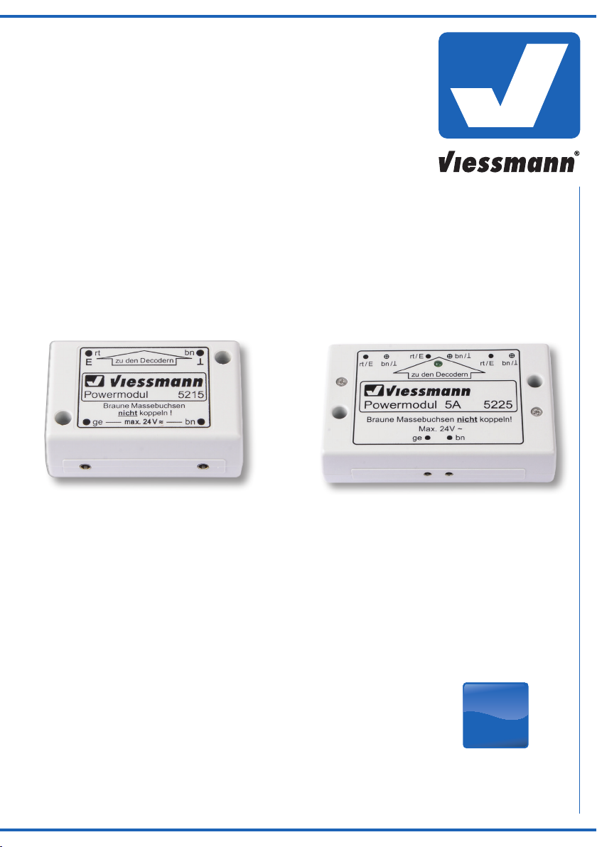
Powermodul
Power module
5215 2A
5225 5A
1. Wichtige Hinweise / Important information ........................................................ 2
2. Einleitung / Introduction ..................................................................................... 2
3. Anschluss / Connection ..................................................................................... 3
4. Einbau / Mounting ............................................................................................. 3
5. Technische Daten / Technical data .................................................................... 4
AC
die bewegt!
Page 2
DE EN
1. Wichtige Hinweise
Bitte lesen Sie vor der ersten Anwendung des Produktes bzw. dessen
Einbau diese Bedienungsanleitung aufmerksam durch. Bewahren Sie
diese auf, sie ist Teil des Produktes.
1.1 Sicherheitshinweise
Vorsicht:
Verletzungsgefahr!
Für die Montage sind Werkzeuge nötig.
Stromschlaggefahr!
Die Anschlussdrähte niemals in eine Steckdose einführen! Verwendetes Versorgungsgerät (Transformator, Netzteil) regelmäßig
auf Schäden überprüfen. Bei Schäden am Versorgungsgerät
dieses keinesfalls benutzen!
Alle Anschluss- und Montagearbeiten nur bei abgeschalteter
Betriebsspannung durchführen!
Ausschließlich nach VDE/EN-gefertigte Modellbahntransforma
toren verwenden!
Stromquellen unbedingt so absichern, dass es bei einem Kurzschluss nicht zum Kabelbrand kommen kann.
1.2 Das Produkt richtig verwenden
Dieses Produkt ist bestimmt:
- Zum Einbau in Modelleisenbahnanlagen und Dioramen.
- Zum Anschluss an einen Modellbahntransformator (z. B. Art.
5200, 5201) bzw. an eine Modellbahnsteuerung mit zugelassener
Betriebsspannung.
- Zum Betrieb in trockenen Räumen.
Jeder darüber hinausgehende Gebrauch gilt als nicht bestimmungsgemäß. Für daraus resultierende Schäden haftet der Hersteller nicht.
1.3 Packungsinhalt überprüfen
Kontrollieren Sie den Lieferumfang auf Vollständigkeit:
- Powermodul
- 2 Schrauben
- Anleitung
1. Important information
Please read this manual completely and attentively before using the
product for the first time. Keep this manual. It is part of the product.
1.1 Safety instructions
-
1.2 Using the product for its correct purpose
This product is intended:
- For installation in model train layouts and dioramas.
- For connection to an authorized model train transformer (e. g.
- For operation in dry rooms only.
Using the product for any other purpose is not approved and is considered inappropriate. The manufacturer is not responsible for any
damage resulting from the improper use of this product.
1.3 Checking the package contents
Check the contents of the package for completeness:
- Power module
- 2 screws
- Manual
Caution:
Risk of injury!
Tools are required for installation.
Electrical hazard!
Never put the connecting wires into a power socket! Regularly
examine the transformer for damage. In case of any damage, do
not use the transformer.
Make sure that the power supply is switched off when you mount
the device and connect the cables!
Only use VDE/EN tested special model train transformers for
the power supply!
The power sources must be protected to avoid the risk of burning
cables.
items 5200, 5201) or a digital command station.
2. Einleitung
Das Powermodul von Viessmann erzeugt aus einer TransformatorenWechselspannung, wie sie vom Lichtstromausgang eines handelsüblichen Modellbahntransformators geliefert wird, eine geglättete
Gleichspannung.
Zum Anschluss an die Decoder Art. 5211, 5231, 5280 und 5285, zur
bestmöglichen Versorgung von mechanischen Signal- und Weichenantrieben sowie weitere Verbraucher. Auch geeignet für die Decoder
anderer Hersteller, sofern diese über separate Spannungseinspeisung verfügen. LED-Leuchten arbeiten flackerfrei und fast doppelt so
hell im Vergleich zur Versorgung über einen Wechselstrom-Trafo. Ein
Powermodul reicht zur Versorgung mehrerer Decoder und bis zu 100
LED-Leuchten (Art. 5215) oder bis zu 250 LED-Leuchten (Art. 5225).
3. Anschluss
Schließen Sie das Powermodul über die beiden Buchsen (braun und
gelb) an einen handelsüblichen Modellbahntransformator an (Abb. 1).
Die Ausgänge des Powermoduls führen zu den Decodern bzw.
anderen Verbrauchern.
ACHTUNG:
Ausgang rot = MINUS
Ausgang braun = PLUS
2
2. Introduction
The power module generates filtered DC from the AC input which
is supplied by a commercially available model railroad transformer.
For connection to the decoders items 5211, 5231, 5280 and 5285,
digital signals or other consumers. Suitable for all decoders even
from other producers in case separate power input is provided. The
power module offers flicker-free lighting by using AC power. Nearly
double brightness is possible. One power module supplies up to 100
LED lights (item 5215) and several digital signals or up to 250 LED
lights (item 5225).
3. Connection
Connect the power module via the two sockets (yellow and brown)
to a commercially available model train transformer (fig. 1).
The two outputs of the power module have to be wired to the digital
decoders or other consumers.
ATTENTION:
Output red = NEGATIVE
Output brown = POSITIVE
Page 3

Vorsicht:
Die beiden braunen Buchsen des Powermoduls dürfen niemals miteinander verbunden werden! Das würde einen Kurzschluss verursachen!
Tipp: Zum einfachen Ein- und Ausschalten verwenden Sie einen
Schalter (z. B. Art. 5550).
Das Powermodul besitzt eine selbstrückstellende Überlastschutzabschaltung. Im Falle eines Ansprechens des Überlastschutzes ist
zunächst die Ursache der Überlastung (wie z. B. Kurzschluss an den
Ausgangsbuchsen) zu beseitigen und die Eingangsspannung abzuschalten. Nach einer Abkühlphase von ca. 1 bis 2 Minuten ist das Powermodul wieder einsatzbereit. Ein Funktionsdiagramm sehen Sie in Abb. 2.
Hinweis:
Wenn die Leistung des Powermoduls Art. 5215 nicht ausreichen
sollte, so können Sie entweder mehrere Powermodule einsetzen
und die Verbraucher entsprechend aufteilen oder Sie verwenden
stattdessen das 5A Powermodul Art. 5225.
Caution:
Never connect the two brown sockets of the power module together. It would cause a short circuit!
Hint: For easy on-off switching use an on-off switch (e. g. item
5550).
The power module includes a self resetting overload protection
unit. If an overload is detected you have to remove the cause of
the overload (e. g. short-circuit on the output sockets) and switch
off the input power. After a cooling time of about 1 to 2 minutes
the power module is ready again for use. Please find a functional
diagram in fig. 2.
Hint:
Should the power output of the power module item 5215 not be sufficient, you can either use several power modules or use the 5A
power module item 5225 instead.
Primär
Lichttransformator
5200
Sekundär
10 V
16 V
z. B. / e. g.
5200, 5201
z. B. / e. g.
5215, 5225
Universal Ein-Aus-Umschalter
viessmann
gelb / yellow
230 V~
Nur für trockene Räume
Primär 230 V 50 - 60 Hz
Sekundär max. 3,25 A52 VA
ta 25°CIP 40
Gefertigt nach
VDE 0570
EN 61558
0-10-16 V~
0 V
braun / brown
Das Powermodul Art. 5225 hat drei Buchsenpaare um die Verkabelung zu erleichtern. Außerdem verfügt dieses Modul über eine
grüne LED, welche die Funktionsbereitschaft anzeigt. Sie erlischt
bei Abschaltung durch Überlastung.
Vorsicht:
Bitte verwenden Sie zur Beschaltung des Powermoduls Querlochstecker wie Art 6870 gelb, 6871 rot, 6873 braun. Empfohlener
Querschnitt für Art. 5225 ab 0,25 mm!
4. Einbau
Befestigen Sie das Powermodul mit den beiliegenden Schrauben am
gewünschten Einbauort.
zu den Verbrauchern
to the consumers
braun / brownrot / red
rt bn
E
viessmann
Powermodul
Braune Massebuchsen
ge bn
braun / brown
z. B. / e. g. 5550
5550
The power module item 5225 has three socket pairs to facilitate
wiring. Furthermore, this module is equipped with a green LED
signaling function standby. It goes out in case of shut-off due to
overloading.
zu den Decodern
nicht koppeln !
max. 24 V~
5215
T
Niemals verbinden!
Do not connect!
Fig. 1Abb. 1
Caution:
When wiring the power module, please use plugs such as items
6870 yellow, 6871 red, 6873 brown. Recommended section for
item 5225 min. 0,25mm!
4. Mounting
Fix the power module with the included screws at the favoured
mounting place.
E
Gleich-
Eingang / Input Ausgang / Output
richter
rectifier
Energiespeicher
power
reservoir
Überlastschutz
overload
protection
MINUS / NEGATIVE
PLUS / POSITIVE
Fig. 2Abb. 2
3
Page 4

Viessmann
hnik GmbH
www.viessmann-modell.de
Hinweis zu Art. 5225:
Dauerhafte Belastung mit hohem Strom führt zu Erwärmung des
Moduls, das Gehäuse kann warm werden.
Vermeiden Sie andere Wärmequellen direkt in der Umgebung des Moduls.
Für Abgabe des Nennstroms über längere Zeit benötigt das Modul
eine gute Durchlüftung. Dazu wird die senkrechte Montage benötigt
(Abb. 3). Der Eingang befindet sich dann an der rechten Gehäuseseite.
Vorsicht!
Vermeiden Sie unbedingt Kurzschlüsse auf der Ausgangsseite
des Moduls, erhebliche Funkenbildung kann auftreten. Dabei
ist auch das Verschweißen der stromführenden Teile möglich.
Hint to item 5225:
Permanent exposure to high current leads to heating of the module,
the housing can become warm.
Avoid other heat sources directly in the vicinity of the module.
The module requires good ventilation to deliver the rated current
over a longer period of time. This requires vertical mounting (fig. 3).
The input is then located on the right side of the housing.
Caution!
It is essential to avoid short circuits on the output side of the
module, considerable sparking can occur. Welding of the live
parts is also possible.
Abb. 3
min. 5 cm
Tischbein / Table leg
5. Technische Daten
Betriebsspannung: max. 24 V AC~
Überlastgeschützt
Art. 5215
Strom: 2A dauernd
Maße: L 5,4 x B 3,4 x H 2,2 cm
Art. 5225
Strom: 5A dauernd
Maße: L 8,7 x B 5,3 x H 2,2 cm
Entsorgen Sie dieses Produkt nicht über den (unsortierten) Hausmüll, sondern führen Sie es der Wiederverwertung zu.
Änderungen vorbehalten. Keine Haftung für Druckfehler und Irrtümer.
Die aktuelle Version der Anleitung finden Sie auf der Viessmann
Homepage unter der Artikelnummer.
Modellbauartikel, kein Spielzeug! Nicht geeignet für Kinder
DE
unter 14 Jahren! Anleitung aufbewahren!
Model building item, not a toy! Not suitable for children
EN
under the age of 14 years! Keep these instructions!
Ce n’est pas un jouet. Ne convient pas aux enfants de
FR
moins de 14 ans ! C’est un produit décor! Conservez cette
notice d’instructions!
Não é um brinquedo!Não aconselhável para menores de
PT
14 anos. Conservar o manual de instruções.
Fig. 3
Tischplatte / Table board
5. Technical data
Operating voltage: max. 24 V AC~
Current protection
Item 5215
Current: 2A continuous
Dimensions: L 5,4 x W 3,4 x H 2,2 cm
Item 5225
Current: 5A continuous
Dimensions: L 8,7 x W 5,3 x H 2,2 cm
Do not dispose of this product through (unsorted)
domestic waste, supply it to recycling instead.
Subject to change without prior notice. No liability for
mistakes and printing errors.
You will find the latest version of the manual on the Viessmann
website using the item number.
Modelbouwartikel, geen speelgoed! Niet geschikt voor
NL
kinderen onder 14 jaar! Gebruiksaanwijzing bewaren!
Articolo di modellismo, non è un giocattolo! Non adatto
IT
a bambini al di sotto dei 14 anni! Conservare istruzioni per
l’uso!
Artículo para modelismo ¡No es un juguete! No
ES
recomendado para menores de 14 años! Conserva las
instrucciones de servicio!
Modelltec
Bahnhofstraße 2a
D - 35116 Hatzfeld-Reddighausen
info@viessmann-modell.com
4
Made in Europe
98036
Stand 06/sw
10/2019
Ho/Kf
 Loading...