

Page 1
Bedienungsanleitung
Operation Manual
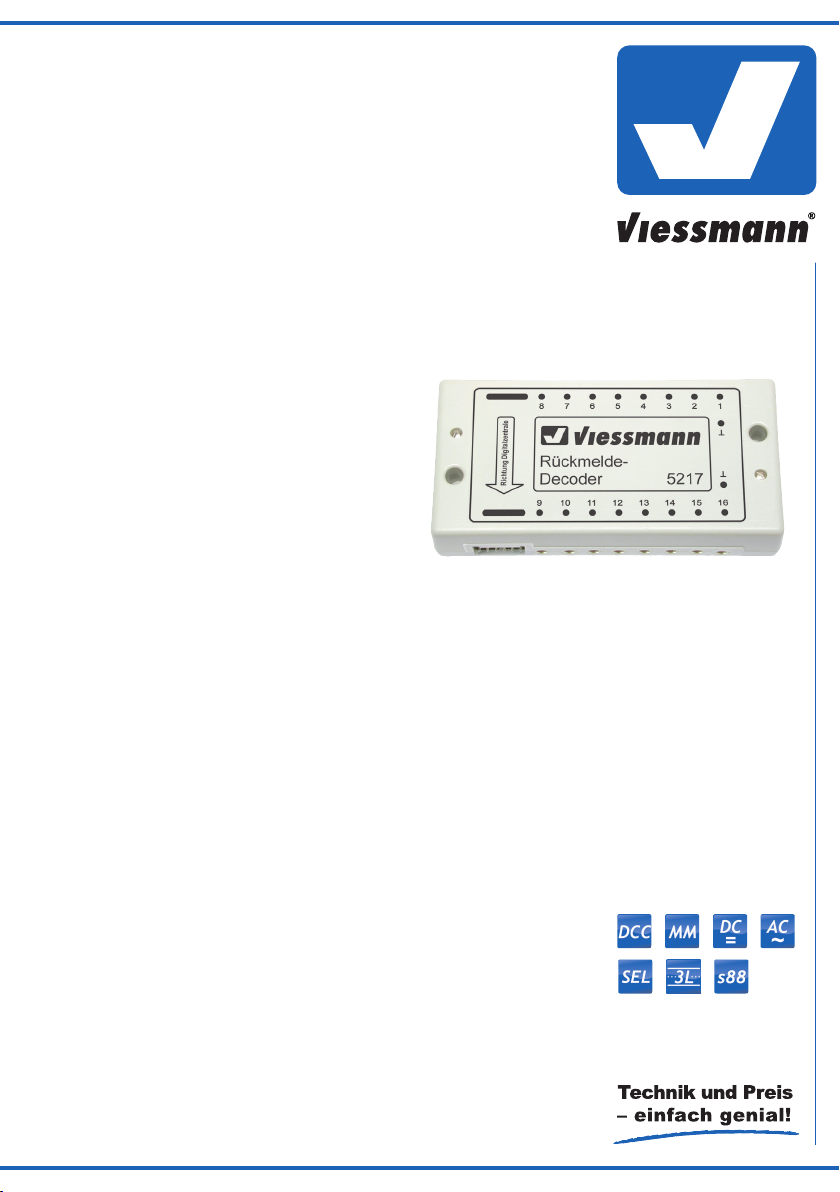
5217
Rückmeldedecoder
für s88-Bus
Feedback decoder
for s88-Bus
1. Wichtige Hinweise / Important information ........................................................ 2
2. Einleitung / Introduction ..................................................................................... 2
3. Anschluss / Connection ..................................................................................... 7
4. Technische Daten / Technical data .................................................................... 8
Page 2
DE EN
1. Wichtige Hinweise
Bitte lesen Sie vor der ersten Anwendung des Produktes
bzw. dessen Einbau diese Bedienungsanleitung aufmerksam durch. Bewahren Sie diese auf, sie ist Teil des Produktes.
1. Important information
Please read this manual completely and attentively be-
fore using the product for the rst time. Keep this manual.
It is part of the product.
1.1 Sicherheitshinweise
Vorsicht:
Verletzungsgefahr!
Aufgrund der detaillierten Abbildung des Originals bzw.
der vorgesehenen Verwendung kann das Produkt Spitzen, Kanten und abbruchgefährdete Teile aufweisen.
Für die Montage sind Werkzeuge nötig.
Stromschlaggefahr!
Die Anschlussdrähte niemals in eine Steckdose einführen! Verwendetes Versorgungsgerät (Transformator, Netzteil) regelmäßig auf Schäden überprüfen. Bei
Schäden am Versorgungsgerät dieses keinesfalls benutzen!
Alle Anschluss- und Montagearbeiten nur bei abgeschalteter Betriebsspannung durchführen!
Ausschließlich nach VDE/EN-gefertigte Modellbahntransformatoren verwenden!
Stromquellen unbedingt so absichern, dass es bei
einem Kurzschluss nicht zum Kabelbrand kommen
kann.
1.2 Das Produkt richtig verwenden
Dieses Produkt ist bestimmt:
- Zum Einbau in Modelleisenbahnanlagen und
Dioramen.
- Zum Anschluss an Kontaktgleisabschnitte (nur bei
Mittelleiter-Schienen) oder Gleiskontakte.
- Zum Betrieb innerhalb eines Modelleisenbahn-Digitalsystems mit s88-kompatiblem Rückmeldebus (wie
z. B. Fleischmann Twin-Center, Märklin Digital und
Uhlenbrock Intellibox).
- Zum Betrieb in trockenen Räumen.
Jeder darüber hinausgehende Gebrauch gilt als nicht bestimmungsgemäß. Für daraus resultierende Schäden
haftet der Hersteller nicht.
1.1 Safety instructions
Caution:
Risk of injury!
Due to the detailed reproduction of the original and the
intended use, this product can have peaks, edges and
breakable parts. Tools are required for installation.
Electrical hazard!
Never put the connecting wires into a power socket!
Regularly examine the transformer for damage.
In case of any damage, do not use the transformer.
Make sure that the power supply is switched off when
you mount the device and connect the cables!
Only use VDE/EN tested special model train transformers for the power supply!
The power sources must be protected to avoid the risk
of burning cables.
1.2 Using the product for its correct purpose
This product is intended:
- For installation in model train layouts and dioramas.
- For connection to contact track sections (only for
third-rail tracks) or track contacts.
- For operation within a model train digital system with
a feedback bus which is compatible to s88 (like the
Fleischmann Twin-Center, Märklin Digital, Uhlenbrock
Intellibox etc.).
- For operation in dry rooms only.
Using the product for any other purpose is not approved
and is considered inappropriate. The manufacturer is not
responsible for any damage resulting from the improper
use of this product.
1.3 Packungsinhalt überprüfen
Kontrollieren Sie den Lieferumfang auf Vollständigkeit:
- Rückmeldedecoder
- 18 Stecker
- 2 Schrauben
- s88-Buskabel
- Anleitung
2. Einleitung
Um eine Modellbahnanlage vorbildgerecht zu steuern,
z. B. per PC oder durch automatische Fahrstraßensteuerungen (Märklin Memory, IB-Switch von Uhlenbrock)
ist die ständige Information über die Belegtzustände der
2
1.3 Checking the package contents
Check the contents of the package for completeness:
- Feedback decoder
- 18 plugs
- 2 screws
- s88-Bus cable
- Manual
2. Introduction
In order to control a model railroad layout according to
the prototype, e. g. by PC or by an automatic route control system (Märklin Memory, IB-Switch from Uhlenbrock),
constant information on track occupancy is essential. The
Page 3

Gleise unerlässlich. Um diese Belegtmeldungen an die
Steuerzentrale zu leiten, hat sich bei vielen Digitalsystemen (Märklin Digital, Uhlenbrock Intellibox, Fleischmann
Twin-Center usw.) der s88-Bus durchgesetzt. An diesen
werden kettenförmig die Rückmeldedecoder angeschlossen, welche “vor Ort” die Belegtzustände erfassen und
über den s88-Bus an die Digitalzentrale senden.
Der Art. 5217 ist ein solcher Rückmeldedecoder und
kann 16 Rückmeldekontakte einlesen.
Einem Rückmeldedecoder müssen Informationen an
seinen Eingängen zur Verfügung gestellt werden. Dieses kann z. B. über potenzialfreie, zugbetätigte Schaltkontakte wie Schaltgleise oder Reedkontakte geschehen. Solche (”Moment”-) Schaltkontakte haben aber die
Eigenschaft, nur genau in jenem kurzen Augenblick einen Stromimpuls zu liefern, in welchem der Zug (oder sogar nur ein bestimmtes Fahrzeug davon) über den Kontakt hinweg fährt. Dieses ist nicht immer sinnvoll. Für
eine PC-Steuerung ist es beispielsweise wünschenswert,
nach dem Einschalten der Anlage direkt die belegten
Streckenabschnitte erkennen zu können. Auch sollten liegengebliebene Waggons sicher registriert werden. Hierzu sind Dauerkontakte erforderlich, welche so lange ein
Signal liefern, wie der überwachte Gleisabschnitt durch
ein Fahrzeug belegt ist. Dieses kann bei bestimmten Mittelleitergleistypen (Märklin C- und K-Gleis) über einseitig isolierte Masseschienenabschnitte (”Kontaktgleisstrecken”) erreicht werden. Ein darauf stehendes Fahrzeug
überbrückt die linke und rechte Masseschiene und kann
somit eine Meldung auslösen.
Dieses recht einfache Verfahren zur Besetztmeldung
funktioniert allerdings nicht in Weichenbereichen, da sich
dort die linken und rechten Masseschienenprofile nur mit
großem bastlerischem Aufwand elektrisch voneinander
trennen lassen. Auch bei Gleisen ohne Mittelleiter ist diese Art der Belegtmeldung nicht möglich. Dort besitzen
beide Schienenprofile unterschiedliche Polarität und ein
Überbrücken mit einem unisolierten Radsatz würde hier
zum Kurzschluss führen.
Zur Lösung dieser Probleme wurde unser Rückmeldedecoder mit Gleisbesetztmelder Art. 5233 entwickelt.
Er besteht aus einem “halben” Rückmeldedecoder Art.
5217, vor dessen 8 Eingänge empfindliche elektronische
Stromsensoren (mit sogenannten “Optokopplern”) geschaltet sind. An diese Stromsensoren können nun entweder die Weichenbereiche von Mittelleitergleisen (d.
h. deren isolierter Mittelleiter) oder einseitig isolierte Abschnitte von Gleisen ohne Mittelleiter (ZweischienenZweileiter-System) angeschlossen werden.
Die Stromsensoren erkennen jedes stromaufnehmende
Fahrzeug auf den überwachten Gleisabschnitten. Dieses
können Lokomotiven oder beleuchtete Waggons mit eigenen Stromabnehmern (Mittelschleifer, Radkontakte) sein.
Bei Zweischienensystemen ist es auch möglich, mit Hilfe von Widerstandslack (nicht zu verwechseln mit Silberleitlack!) die Achsisolierungen der Radsätze von unbeleuchteten Waggons hochohmig zu überbrücken. Dadurch werden die Waggons zu (geringen) Stromverbrauchern und auch von den Stromsensoren des Art. 5233
erkannt. Alternativ können für H0 auch die von Roco erhältlichen Widerstands-Radsätze 40186 und 40187 verwendet werden.
Der Rückmeldedecoder Art. 5217 ist voll kompatibel mit
dem Märklin Digital-Decoder s88. An seinen 16 Eingän-
s88 bus has become the standard for digital systems for
directing these occupied messages to the command station. The feedback decoders are connected to this bus in
a chain and detect the occupied states “on-site” and send
them to the digital command station via the s88 bus.
Item 5217 is such a feedback decoder which can read in
16 feedback contacts.
A feedback decoder must be provided with information at
its inputs. This can be achieved with potential-free, traintriggered switch contacts such as switching tracks and
reed contacts. Such “instant” switch contacts have the
property to only provide a pulse of current for the short
moment in which the train (or even a particular car of the
train) moves over the contact. This does not always make
sense. For a PC control system, for example, it is desirable to be able to directly recognize the occupied sections
of the route after the system is switched on. Cars that are
left standing should also be recognized. This requires
constant contacts that provide a signal for as long as the
monitored route section is occupied by a vehicle. For cer-
tain third-rail track types (Märklin C- and K-track), this can
be achieved using grounding rail sections insulated on
one side (“contact track sections”). A vehicle located on it
bridges the left and right grounding rails, thereby triggering a signal.
However, this quite simple procedure to detect occupied
track sections does not work in turnout areas, because
the left and right grounding rail sections there can only be
electrically separated from each other with a lot of handwork. This type of occupation detection is also not possible for tracks without a third rail. For this track type, both
rail profiles have a different polarity, and bridging with an
uninsulated set of wheels would lead to a short circuit.
Our feedback decoder with track occupancy detector
item 5233 was developed to solve this problem. It consists of a “half” feedback decoder item 5217 to whose 8
inputs sensitive electronic current sensors are connected
(via “optocouplers”). To these current sensors, you can
then connect either the turnouts areas of third-rail tracks
(i. e. their insulated third rail) or the sections of tracks insulated at one side without third rail (two-rail/two conductor system).
The current sensors recognize every power-consuming
vehicle on the monitored section of track. These can be
locomotives or illuminated cars with their own power pickups (center slider, wheel contact).
For two-rail systems, it is also possible to bridge the axle
insulation of the wheel sets of unlighted cars with high resistance using resistor paint (do not confuse with silver
conductor paint!). This turns the cars into (slight) power consumers so that they are recognized by the power
sensors of item 5233. As an alternative for H0, the resistor wheel sets (40186 and 40187) from Roco can also
be used.
The feedback decoder item 5217 is compatible with the
Märklin digital decoder s88. The 16 inputs of the decoder
are qualified for connecting to contacts, which are switching to ground, e. g. circuit tracks, reed switches, push
button switches (see fig. 5). With the feedback decoder
item 5217 the digital control system is able to recognize
and analyze proceedings running at the layout and to react appropriately.
3
Page 4

5217
von weiteren Decodern
Art. 5217 oder Art. 5233
from further decoders
item 5217 or item 5233
zur Digitalzentrale
to the digital command
station
Abb. 1
(Eingänge 9 bis16)
(inputs 9 to16)
(Eingänge 1 bis 8)
(inputs 1 to 8)
(Eingänge 17 bis 32)
(inputs 17 to 32)
2
1a
1b
5217
5233
5233
Digitalzentrale
digital command station
gen können sämtliche gegen Masse schaltenden Kontakte angeschlossen werden (z. B. Reed-Kontakte,
Schaltgleise oder Kontaktgleisstrecken (siehe Abbildung
5). Dadurch ist das Steuersystem der Anlage in der Lage,
Vorgänge auf der Anlage zu erkennen, diese auszuwerten und entsprechend zu reagieren.
Fig. 1
2.1 Anschluss des Decoders am
Digitalsystem
Der Decoder wird bei abgeschalteter Stromversorgung
des Digitalsystems über das beiliegende Spezialkabel direkt mit der sich auf der Rückseite des Memorys oder
des Interfaces (Märklin, Arnold alt), der Intellibox (Uhlenbrock) bzw. des Twin-Centers (Fleischmann) befindlichen
6-poligen s88-Steckbuchse verbunden. Die richtige Stellung des Spezialsteckers ist dabei unbedingt zu beachten (siehe Abb. 1). Dieser muss in sämtlichen Geräten so
eingesteckt werden, dass das Flachbandkabel nach unten verläuft.
Abb. 2
2.1 Connecting the decoder to the
digital system
The decoder is connected directly to the 6-pin s88 socket at the rear of the Memory or the Interface (Märklin or
Arnold), of the Intellibox (Uhlenbrock), or the Twin-Center (Fleischmann) via the included special cable, with the
power of the digital system switched off. Be absolutely
sure the special plug is positioned correctly (see fig. 1).
It must be inserted in all devices so that the ribbon cable
runs downward.
Fig. 2
4
Page 5

Am Märklin Interface, dem Fleischmann Twin-Center und
1
2
n (n <= 31)
A1 ... A8
B1 ... B8
C1 ... C8
der Uhlenbrock Intellibox können bis zu 31 Rückmeldedecoder Art. 5217 oder 62 Rückmeldedecoder mit Gleisbelegtmelder Art. 5233 angeschlossen werden. Ein Rückmeldedecoder Art. 5217 (16 Eingänge) kann also durch
zwei Art. 5233 mit jeweils 8 Eingängen ersetzt werden.
Die Summe aller Decodereingänge kann maximal 496
betragen.
Rückmeldedecoder mit Gleisbelegtmelder Art. 5233 und
Rückmeldedecoder Art. 5217 (oder s88) können miteinander kombiniert werden.
Die Decoder werden dabei automatisch von der Zentrale
bzw. dem Interface fortlaufend von 1 bis 31 durchnummeriert. Je zwei aufeinanderfolgende Art. 5233 Decoder erhalten dabei die gleiche Adresse (siehe Abb. 2).
Bitte beachten:
• Beim Anschließen des Spezialkabels den Strom immer abschalten!
• Der am Rückmeldedecoder aufgedruckte Pfeil muss
in Richtung Digitalzentrale zeigen!
• Bitte beachten, dass Teile des Decoders sehr sensibel auf statische Spannungen reagieren!
• Das Spezialkabel vorsichtig auf die Kontaktstifte aufstecken (die Stifte können leicht verbogen werden)!
Up to 31 feedback decoders item 5217 or 62 feedback
decoders with track occupancy detectors item 5233 can
be connected to the Märklin Interface, the Fleischmann
Twin-Center, or the Uhlenbrock Intellibox. This means
that one feedback decoder item 5217 (16 inputs) can be
replaced by two item 5233’s with 8 inputs each. The total
number of decoder inputs can be up to 496.
The feedback decoder with track occupancy detector
item 5233 and the feedback decoder item 5217 (or s88)
can be combined with each other in any sequence.
The decoders are automatically numbered in sequence
from 1 to 31 by the central control unit or the interface.
Two consecutive item 5233 decoders each get the same
address (see fig 2).
Please note:
• Always switch off the power when connecting the
special cable!
• The arrow printed on the feedback decoder must
point in the direction of the digital control center!
• Please note that parts of the decoder are very sensitive to static electricity!
• Plug the special cable carefully onto the contact pin
(the pins bend easily)!
Abb. 3
Fig. 3
Abb. 4
Fig. 4
5
Page 6

2.2 Spezielle Hinweise für die Intellibox
Sekundär
0-10-16 V~
16 V
Primär
230 V~
Gefertigt nach
VDE 0570
EN 61558
Lichttransformator
5200
Nur für trockene Räume
Primär 230 V 50 - 60 Hz
Sekundär max. 3,25 A52 VA
ta 25°CIP 40
10 V
0 V
5217
0L B
Kontaktgleisstrecke
contact track section
von weiteren Decodern
from further decoders
Schaltgleis
switching track
Schalt-
kontakt,
z. B. Art.
6840
switching
contact,
e. g. item
6840
und das Twin-Center:
Der Anschluss erfolgt an die mit “s88” gekennzeichnete Buchse. Im Grundeinstellungsmenü muss unter dem
Punkt “s88-Einstellungen” eingetragen werden, wie viele
Rückmeldedecoder angeschlossen sind.
2.2 Special information for the Intellibox
and the Twin-Center:
The connection is made at the socket marked „s88“. In
the basic settings menu, you must enter how many feedback decoders are connected under the point „s88 settings“.
2.3 Spezielle Hinweise für das Memory:
An ein Memory von Märklin können maximal drei Art.
5217 angeschlossen werden. Diese werden mit dem Einschalten des Systems automatisch vom Memory adressiert. Die Eingänge des Rückmeldedecoders Art. 5217
sind in 2 Gruppen aufgeteilt (1 – 8 und 9 – 16). Mit Betätigung des Eingangs “1” wird eine vorher programmierte
Fahrstraße aktiviert (d. h. Signale, Weichen usw. gehen
in die gewünschte Stellung). Im Zielpunkt angekommen,
muss die erste Fahrstraße über den Eingang “9” wieder
freigegeben werden. So gehört zum ersten Eingang der
neunte Eingang, zum zweiten Eingang der zehnte usw.
Bei drei Rückmeldedecodern können bis zu 24 Fahrstraßen programmiert werden. Eine Fahrstraße kann bis
zu 20 Befehle enthalten. Die Tastengruppe A1 – A8 entspricht dem ersten Decodereingang (siehe Bild 4). Die
Tastengruppe B1 – B8 bildet Einheit 2 bzw. C1 – C8 Einheit 3. Es besteht die Möglichkeit, die externe Auslösung
der Schaltfunktion mit den Tasten “extern”, bzw. “off” anund auszuschalten und somit die Anlage von Hand- auf
Automatikbetrieb umzustellen. Durch die entsprechende
Stellung des Codierschalters auf der Memoryrückseite
ist es möglich, den Aufruf einer neuen Fahrstraße zu verhindern.
Abb. 5
2.3 Special information for the memory:
Up to three items 5217’s can be connected to a Memory from Märklin. These will be addressed automatically
by Memory when you switch on the system. The inputs
of the feedback decoders are divided up into two groups
(1 – 8 and 9 – 16). By operating input “1”, a route programmed before can be activated (signals and turnouts
switch to a predefined position). When the train arrives
at its destination, the first route has to be released by input “9”. The first input belongs to the ninth, the second
to the tenth one, etc. With three feedback decoders you
are able to program 24 routes. A route can contain up to
20 commands altogether. The keygroup A1 – A8 corresponds to the first decoder input, keygroup B1 – B8 to the
second and C1 – C8 to the last one (see fig. 4). It is possible to turn on and off the external trigger of switch-function by the Memory keys “extern” and “off”. So the system
can be toggled between manual and automatic running.
By adjusting the code switch on the backside of the Memory, it is possible to block the call of a new route.
Fig. 5
6
Page 7

Benutzung der Viessmann-Stecker
Using the Viessmann plugs
Kabel abisolieren
1
Dismantle the
cable
Stecker aufschieben
3
Push plug on
ca. 1,5 cm
3. Anschluss
3.1 Anschluss an (Märklin-)
Mittelleitergleise:
Die verschiedenen Anschlussmöglichkeiten an (Märklin-)
Mittelleitergleisen sind in Abbildung 5 dargestellt. Neben
der Einrichtung von Kontaktgleisstrecken durch einseitig
auf-getrennte Masseschienen ist auch die Verwendung
der Märklin-Schaltgleise möglich. Auch diese schalten bei
Auslösung durch den Fahrzeugschleifer gegen Masse
und können somit eine Meldung an dem Rückmeldedecoder Art. 5217 erzeugen.
3.2 Anschluss an ZweischienenZweileitergleisen:
Leider ist der direkte Anschluss des Art. 5217 an Zweischienen-Zweileitergleise nicht möglich. Dazu müsste ein
Gleisbelegtmelder vor jeden Eingang des Art. 5217 geschaltet werden.
Alternativ empfehlen wir die Verwendung des Rückmeldedecoders Art. 5233 (siehe Abschnitt “Einleitung”).
3.2 Anschluss an Schaltkontakte:
Unabhängig von der Art des Gleissystems können an
den Eingängen auch potenzialfreie Schaltkontakte (z. B.
magnetbetätigte Reedkontakte) angeschlossen werden.
Hier bei ist zu beachten, dass der zweite Anschluss des
Schaltkontakts an einer der beiden Massebuchsen seitlich am Decoder Art. 5217 angeschlossen werden muss.
Bitte benutzen Sie zur Vermeidung von Störungen immer
die Massebuchsen an dem Decoder, an dem der jeweilige Kontakt angeschlossen ist.
Litzen verdrillen
2
Twist wires together
Draht umbiegen
4
Bend wire
3. Connection
3.1 Connecting to (Märklin) third-rail
track:
The various possibilities to connect the item 5217 to Märklin third rail tracks are shown in fig. 5. You can make
contact track sections with single side insulations of the
grounding rail. In addition you can use Märklin switching
tracks because they also switch against ground if they
are activated by the cars’ center slider.
3.2 Connecting to two-rail / twoconductor systems:
Connecting the item 5217 directly to two-rail / two-conductor track unfortunately is not possible. For this you
would have to put an occupancy detector in front of every
input of the item 5217.
Instead we recommend to use the feedback decoder item
5233 (please refer to section “introduction”).
3.3 Connecting to switching contacts:
Independent of your track system you can connect potential free switching contacts (like reed contacts which are
activated by magnets underneath the vehicles) to the inputs of the item 5217 decoder. Then you have to connect
the second cable from the switching contact to one of the
two grounding sockets located at the right side of the item
5217 feedback decoder. To avoid jammings please always use the grounding sockets of the same decoder to
which the contact is connected.
Dieses Symbol kennzeichnet einen zugbetätigten Schaltkontakt, z. B. einen Reed- (Magnet-) Kontakt (Art. 6840)
oder ein Schaltgleis.
Das obenstehende Symbol kennzeichnet eine Leitungsverbindung. Die sich hier kreuzenden Leitungen müssen
an einer beliebigen Stelle ihres Verlaufs elektrisch leitend
miteinander in Verbindung stehen. Der Verbindungspunkt
muss nicht exakt an der eingezeichneten Stelle sitzen,
sondern kann z. B. zu einem Stecker an einer der kreuzenden Leitungen verlagert werden.
This sign is used for a train-controlled momentary switching contact like a reed (magnetic) contact (item 6840) or
a switching track.
The symbol above designates a cable connection. The
cables that cross here must be in electrical contact with
each other at some point along their length. The connection point does not have to be exactly at the marked
point, but rather can be moved to a plug located at one of
the crossing cables.
7
Page 8

Dieses Symbol neben dem Gleis kennzeichnet eine elektrische Trennstelle (z. B. mit Isolierschienenverbindern)
an der gekennzeichneten Gleisseite. Bei Märklin-Gleisen
entspricht dieses einer Mittelleiter-Trennstelle.
This sign next to the track designates an electrical track
separation point (e. g. with insulating track connectors) at
the marked side of the track. For Märklin tracks, this is a
center-conductor separation point.
4. Technische Daten
Abmessungen 109 x 54 x 23,5 mm
Datenformat s88 - Format
Eingänge 1 – 16
Polarität reagieren auf
Masse-Impulse ( )
Entsorgen Sie dieses Produkt nicht über den
(unsortierten) Hausmüll, sondern führen Sie
es der Wiederverwertung zu.
Änderungen vorbehalten. Keine Haftung für Druckfehler
und Irrtümer.
Die aktuelle Version der Anleitung nden Sie auf der
Viessmann Homepage unter der Artikelnummer.
Modellbauartikel, kein Spielzeug! Nicht geeignet für Kinder
DE
unter 14 Jahren! Anleitung aufbewahren!
Model building item, not a toy! Not suitable for children
EN
under the age of 14 years! Keep these instructions!
Ce n’est pas un jouet. Ne convient pas aux enfants de
FR
moins de 14 ans ! C’est un produit décor! Conservez cette
notice d’instructions!
Não é um brinquedo!Não aconselhável para menores de
PT
14 anos. Conservar a embalagem.
4. Technical data
Dimensions 109 x 54 x 23,5 mm
Data format s88 - format
Inputs 1 – 16
Polarity react on
ground impulses ( )
Do not dispose of this product through (unsorted)
domestic waste, supply it to recycling instead.
Subject to change without prior notice. No liability for
mistakes and printing errors.
You will nd the latest version of the manual on the
Viessmann website using the item-No.
Modelbouwartikel, geen speelgoed! Niet geschikt voor
NL
kinderen onder 14 jaar! Gebruiksaanwijzing bewaren!
Articolo di modellismo, non è un giocattolo! Non adatto
IT
a bambini al di sotto dei 14 anni! Conservare instruzioni
per l’uso!
Artículo para modelismo ¡No es un juguete! No
ES
recomendado para menores de 14 años! Conserva las
instrucciones de servicio!
Modelltechnik GmbH
Bahnhofstraße 2a
D - 35116 Hatzfeld-Reddighausen
8
www.viessmann-modell.de
Made in Europe
98338
Stand 03/sw
09/2018
Ho/Kf
 Loading...