

Page 1

Gebrauchsanleitung
Manual
5132
Wasserkran für Dampflok-BWs
Water Crane For Depots
DE
1. Wichtige Hinweise ...................................... 2
2. Inhalt .......................................................... 2
3. Einleitung .................................................... 2
4. Funktionskontrolle ...................................... 3
5. Montage ..................................................... 4
6. Anschluss ................................................... 4
7. Fehlersuche & Abhilfe ................................ 6
8. Technische Daten ...................................... 6
EN
1. Important Information ................................. 2
2. Content ....................................................... 2
3. Introduction ................................................ 2
4. Checking the function ................................. 3
5. Mounting .................................................... 4
6. Connections & Wiring ................................ 4
7. Troubleshooting .......................................... 6
8. Technical Data ........................................... 6
Page 2

DE
EN
1. Wichtige Hinweise
Lesen Sie vor der ersten Benutzung des Produktes bzw. dessen Einbau diese Anleitung komplett und aufmerksam durch. Bewahren Sie diese
Anleitung auf. Sie ist Teil des Produktes.
Das Produkt richtig verwenden
Das Produkt darf ausschließlich dieser Anleitung
gemäß verwendet werden. Dieser Wasserkran
ist bestimmt
•zumEinbauineineModelleisenbahnanlage
oder ein Diorama
• zumAnschlussandasmitgelieferteSchaltmodul und darüber an einen zugelassenen
Modellbahntransformator bzw. an einer damit
versorgten elektrischen Steuerung
•zumBetriebintrockenenRäumen.
Jeder darüber hinausgehende Gebrauch gilt als
nicht bestimmungsgemäß. Für daraus resultierende Schäden haftet der Hersteller nicht.
2. Inhalt
Beachten Sie:
Das Modell des Wasserkrans besteht aus
ligranenKunststoffteilenundeineremp-
ndlichenAntriebsmechanik.Dahersollten
Sie den Wasserkran nie am Kran selbst,
sondern nur an der Bodenplatte oder der
Antriebseinheit anfassen.
Packungsinhalt überprüfen
Kontrollieren Sie nach dem Auspacken den Lieferumfang auf Vollständigkeit:
►WasserkranmitAntriebseinheit,
►SchaltmodulfürdenelektrischenAnschluss,
►dieseAnleitung.
3. Einleitung
Die bewegten Modelle der Serie eMotion sorgen
für Leben auf der Modelleisenbahn.
Der speziell entwickelte Antrieb ist mit einer elektronischen Steuerung ausgerüstet, die realistische
Bewegungsabläufe erzeugt. Der Antrieb ist fest
mit dem Modell verbunden.
Die elektronische Steuerung des Wasserkrans ist
im mitgelieferten Schaltmodul untergebracht. Mit
Hilfe des Schaltmoduls wird die Drehbewegung
des Krans gesteuert und die Abschaltung des Motors bei Erreichen der Endpositionen sichergestellt.
2
1. Important Information
Please read this manual prior to rst use of the
product resp. its installation! Keep this manual. It
is part of the product.
Using the product for it’s correct
purpose
This product must only be used as required in
this manual. This model is intended
• for installation in model railroad layouts and
dioramas,
• for connection to the enclosed electronic box
„Schaltmodul“ and via that ot an authorized
model railroad transformer or an electrical
control system connected to one
• for operation in a dry area.
Using the product for any other purpose is not
approved and is considered incorrect. The
manufacturer cannot be held responsible for
any damage resulting from the improper use of
this product.
2. Content
Caution:
The model of the water crane is made of
very small and detailed plastic parts and a
sensitive drive unit.
So if you mount or unmount the model,
don’t pull the water crane. Carefully take
the drive unit or the ground plate instead
and push it up.
Checking the package contents
Check the contents of the package for completeness after unpacking:
► Water crane with drive unit,
► Switching module for the electrical connections,
► this manual.
3. Introduction
The Viessmann moving models bring life to your
model train layout.
The especially developed drive unit contains a
controller, which generates realistic movements.
The drive unit is xed to the model.
The controller of the water crane is integrated in
the enclosed switching module “Schaltmodul”. By
the switching module, the rotation of the crane
and the stop at the end positions is controlled.
Page 3
90°
Der Wasserkran ist elementarer Bestandteil jedes
Dampok-Betriebswerksundwarhäugauchan
Lokeinsatzstellenzunden.Erdientdazu,den
WasservorratvonDampokomotivenaufzufüllen.
Der Wasserkran steht neben dem Gleis und
wird zum Betanken einer Lok über das Gleis geschwenkt. Dazu fährt die Lok zunächst bis zur
Tankposition auf dem Gleis (abhängig davon, wo
bei der jeweiligen Baureihe der Einfüllstutzen zu
ndenist).AnschließendwirdderKranherübergeschwenkt und dann heißt es „Wasser marsch!“.
Wenn der Tank gefüllt ist, wird das Wasser abgestellt und der Kran wieder in seine Parkposition
geschwenkt. Jetzt darf die Lok, mit frischem Wasser versorgt, weiterfahren.
Mit dem Viessmann Wasserkran können Sie diesen Vorgang nun auch im Modell nachbilden und
so richtig Betrieb machen.
4. Funktionskontrolle
Nehmen Sie den Wasserkran vorsichtig aus der
Verpackung. Führen Sie vor der Montage eine
Funktionskontrolle durch.
►SchließenSiedazudenWasserkrangemäß
Abbildung 4 an das Schaltmodul an.
►VerbindenSiedenStromanschluss(beschriftet
mit „16 V=/~“) des Schaltmoduls mit einem geeigneten Modellbahntransformator (z. B. Viess-
mann 5200 oder 5201)
►VerbindenSieabwechselndjeweilsdasbraune
Kabel des Trafos zusätzlich mit den beiden mit
Pfeilen markierten Eingängen des Schaltmoduls. Schließen Sie niemals beide Eingänge
gleichzeitig an den Trafo an. Das kann zur
Zerstörung des Wasserkrans führen.
Der Wasserkran schwenkt um 90° und stoppt in
seiner Endlage, sobald der jeweilige Eingang kurz
mit dem Trafo verbunden wird.
The water crane is a typical part of every depot for
steam engines. It is needed to ll up the locomo-
tions with water.
The water crane stands beside the track. To tank
up a loco, the crane is slewed over the track, after the loco drove to the tank position (the exact
position of the loco depends on the position of
the neck). When the tank is full, the crane will be
slewed back to the neutral position and the loco is
allowed to travel on.
The Viessmann water crane allows to demon-
strate this very realistic on the model railroad too.
4. Checking the function
Remove the water crane from the box carefully.
Check all functions prior to installation.
Connect the water crane to the switching module
as shown in gure 4.
Connect the power input of the switching module
(labeled with “16 V=/~”) to a 16 V transformer for
model railways (e. g. Viessmann 5200 or 5201).
Then alternately make contact between the brown
output of the transformer and the control inputs of
the switching module (labeled with arrows).
Never connect the both inputs at the same
time to the transformer. This may destroy the
water crane.
When you connect the inputs with the transformer,
the water crane rotates 90° and stops in the re-
spective end position.
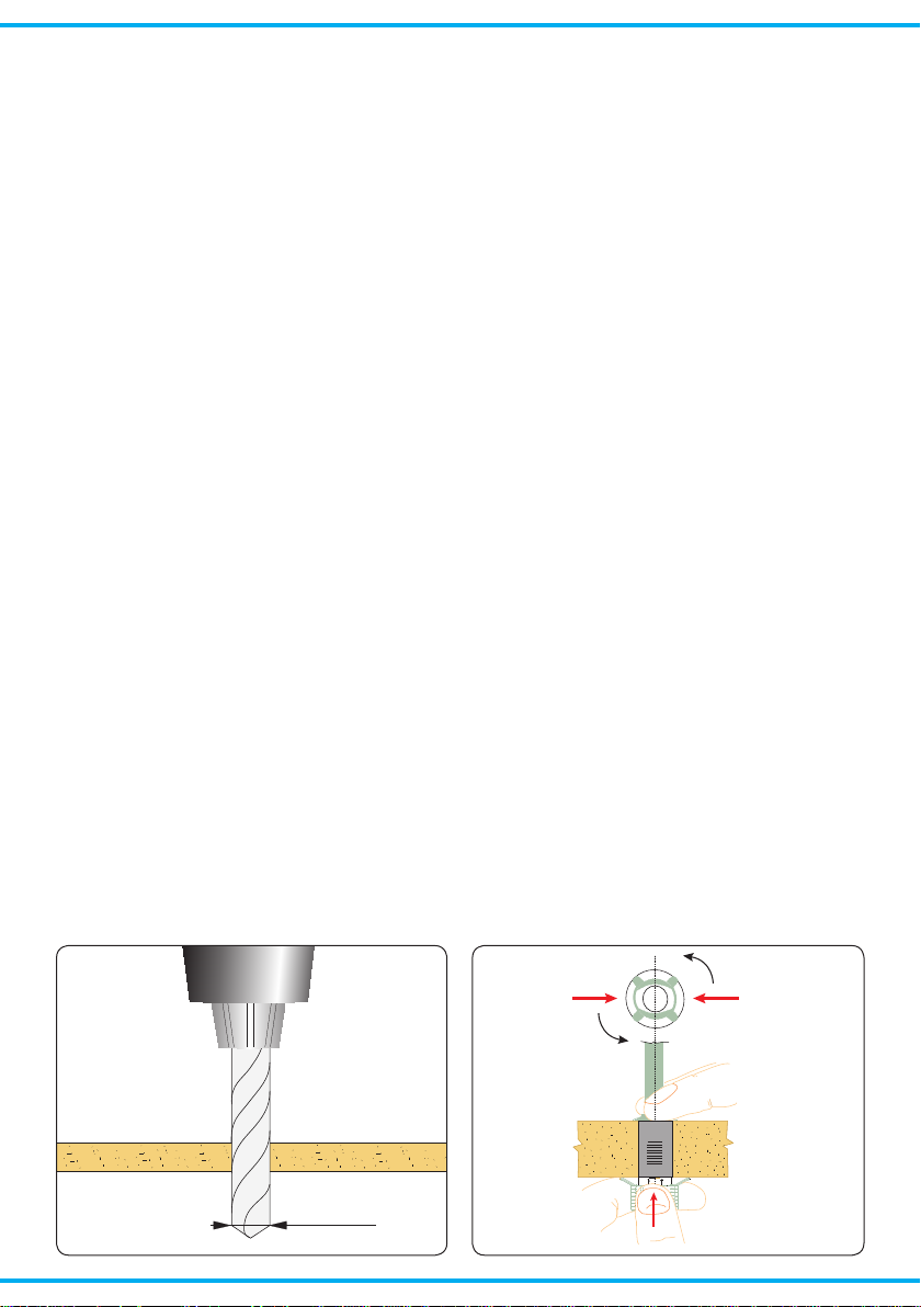
Abb. 1
12 mm
Fig. 1
Abb. 2
Fig. 2
3
Page 4
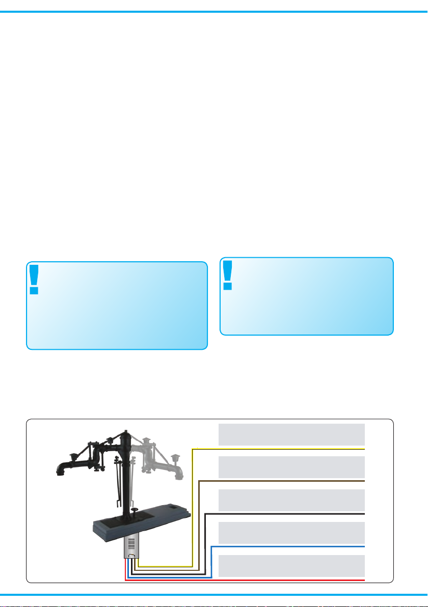
braun
gelb
schwarz
blau
rot
Motor
Motor
Masse
Endlagenkontakt
Endlagenkontakt
brown
yellow
black
blue
red
drive
drive
ground
end position contact
end position contact
5. Montage
1. Bohren Sie an der Montagestelle ein Loch mit
einem Durchmesser von 12 mm (Abb. 1).
2. Führen Sie die Anschlusskabel von oben durch
das Montageloch und stecken Sie dann den
Wasserkran mit dem Antrieb voran hinein.
3. Befestigen Sie den Wasserkran mit dem beiliegenden Befestigungsring. Führen Sie dazu alle
Kabel des Signals durch den Ring. Die Federn
des Rings müssen in Richtung des Wasserkrans zeigen (Abb. 2).
Halten Sie den Wasserkran am Sockel fest.
Schieben Sie den Ring über den Antrieb und
drücken Sie ihn gegen die Modellbahnplatte.
Drehen Sie den Ring um 90° um ihn zu arretieren
4. Schrauben Sie das Schaltmodul nahe beim An-
triebunteruraneinengeeignetenTräger(z.B.
Anlagengrundplatte oder Spanten). Die Kabel
des Wasserkrans müssen ohne mechanische
Spannung bis zum Schaltmodul reichen.
6. Anschluss
Alle Anschluss- und Montagearbeiten dürfen
nur bei abgeschalteter Betriebsspannung
durchgeführt werden!
Verwenden Sie nur nach VDE /EN-gefertigte
Modellbahntransformatoren!
Sichern Sie die Stromquellen unbedingt so
ab, dass es bei einem Kurzschluss nicht
zum Kabelbrand kommen kann.
Die Betriebsspannung beträgt 16 V = / ~.
Schließen Sie den Wasserkran und das Schaltmodul gemäß den Abbildungen 4 oder 5 an. Zur Bedeutung der Kabelfarben siehe Abbildung 3.
Abb. 3
5. Mounting
► Check that the water crane works properly as
per the instructions above before you start installing it on the layout.
► Drill a hole of 12 mm diameter at the mount-
ing place (Fig. 1).
► Insert the connection wires into the hole rst.
Then put the water crane with the drive rst
into the hole.
► Attach the signal to the baseboard with the
enclosed ring. Put the ring over the cables
and the drive unit of the signal (Fig. 2).
Turn the ring 90° to arret it.
► Fix the switching module with screws near to
the drive unit of the water crane on a suitable
support (e. g. the ground plate of your model
railway).
The cable of the drive unit have to reach the
switching module.
6. Connections & Wiring
The operation voltage is 16 V AC or DC.
Installation and electrical wiring may only
be carried out while the power supply is
switched off.
Only use transfor mers compliant with
VDE / EN standards.
The power sources must be protected to
prevent the risk of burning wires.
Now make the electrical connection as per gure 4 or 5. For the meaning of the cable colours
refer to gure 3 (see below).
Fig. 3
4
Page 5
viessmann
Schaltmodul
16 V=/~
- +
ge bn
bl rt sw bn ge
M
Universal Tasten - Stellpult
5547
Viessmann
braun
gelb
rot
grün
z. B. 5547
brown
yellow
red
green
e. g. 5547
16 V ~ / =
5132
viessmann
Schaltmodul
16 V=/~
- +
ge bn
bl rt sw bn ge
M
DCC-
Schaltdecoder
5209
Viessmann
Adresse
–
–
+
+
–
–
+
+
J K 1 gnrt
4 3
2 gnrt
gnrtgn rt
braun
gelb
rot
grün
z. B. 5209
braun
rot
brown
yellow
red
green
e. g. 5209
brown
red
16 V ~ / =
5132
Digital
(Mot. / DCC)
viessmann
Schaltmodul
16 V=/~
- +
ge bn
bl rt sw bn ge
M
rot
blau
braun
schwarz
gelb
red
blue
brown
black
yellow
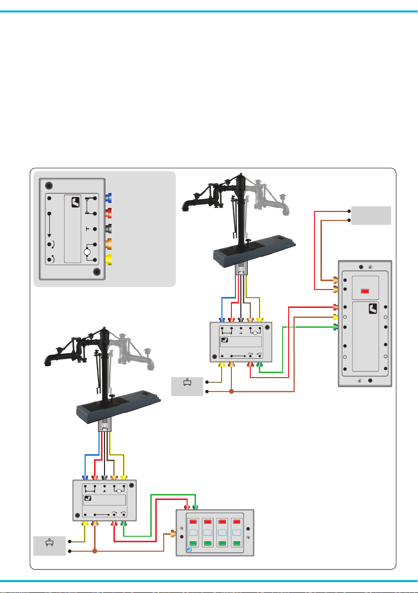
Gleichstrombetrieb: Schließen Sie das gelbe
Kabel an den Minuspol des Trafos an.
Analoge Ansteuerung
Abbildung 4 zeigt, wie Sie den Wasserkran mit
Hilfe des Viessmann Tastenstellpultes 5547 anschließen können. Schalter, Taster und Relais anderer Hersteller können Sie natürlich auch nutzen.
Digitale Ansteuerung
Der Viessmann-Wasserkran kann auch von einem
Digitalsystem angesteuert werden (Abb. 5). Beim
Anschluss z. B. an den Viessmann-Schaltdecoder 5209 (Mot. und DCC) müssen Sie darauf ach-
Direct current: Connect the yellow cable to the
negative pole of the transfomer.
Analogue Wiring
The conventional wiring is shown in gure 4. It
shows how you can connect the water crane to a
push-button panel (e. g. 5547).
Digital Control
The Viessmann water crane can also be operated
with a digital system. Refer to gure 5 (see below)
for the correct wiring.
Abb. 4
Fig. 4
Abb. 5
Fig. 5
5
Page 6
ten, dass neben dem roten und grünen Kabel zur
Signalsteuerung auch das braune Kabel für die
Stromversorgung angeschlossen ist. Zum digitalen Schalten des Wasserkrans wird eine Ausgangsgruppe eines Schaltdecoders benötigt.
Der Schaltdecoder 5209 (4-fach) ist kompatibel
zum Märklin-Motorola und Märklin-Systems-Format sowie zum NMRA-DCC-Format. Damit lässt
er sich mit den meisten am Markt vorhandenen
Digitalzentralen wie z. B. Viessmann Commander,
Digital plus (Lenz), Arnold Digital, Roco Digital,
Fleischmann Twin Center, Digitrax, Uhlenbrock Intellibox, Tillig Digital, Märklin CS2 usw. steuern.
7. Fehlersuche & Abhilfe
Jedes Viessmann-Produkt wird unter hohen Qualitätsstandards gefertigt und vor seiner Auslieferung
geprüft. Sollte es dennoch zu einer Störung kommen, können Sie anhand der folgenden Punkte
eine erste Überprüfung vornehmen. Testen Sie jedoch zuvor die Stromzuführungen.
1. Der Wasserkran schwenkt über die Ruhestellung hinaus oder erreicht diese nicht
ganz:
Wasserkran in Ruhestellung stellen und Kran
vorsichtig von Hand in richtige Position bringen.
Der Kran lässt sich auf seiner Drehachse verstellen.
Sollte das Produkt beschädigt sein, geben Sie es
in der zugehörigen Verpackung zu Ihrem Fachhändler oder senden Sie es direkt an den
Viessmann-Service (Adresse siehe unten).
Simply connect the wires to a digital switching decoder (e.g. Viessmann 5209 for Mot. and DCC).
Remind, that all three cables (brown, red, green)
are connected to the digital switching decoder.
The digital switching decoder 5209 (4 outputs)
is compatible to the Märklin-Motorola and the
NMRA-DCC system. Therefore it is compatible
with the following digital command stations: Viessmann Commander, Digital plus (Lenz), Arnold
Digital, Roco Digital, Fleischmann Twin Center,
Digitrax, Uhlenbrock Intellibox, Tillig Digital, Märklin CS2 etc.
7. Troubleshooting
Every Viessmann-product is manufactured under
high quality standards and is tested before delivery. If there is a fault nevertheless, you can do a
rst check. At rst check the power supply.
1. The water crane slews out of the neutral position:
Set the water crane to the neutral position and
adjust the arm of the crane to the correct position very careful! The water crane can be shifted on its axle.
If the product is damaged, send it in the original
package directly for repair to your local dealer or
to the Viessmann company (see below for ad-
dress).
8. Technische Daten
Betriebsspannung 16 Volt =/~
Stromaufnahme ca. 100 mA
Umgebungstemperatur (Betrieb) 0 - + 60 °C
Zulässige relative Luftfeuchtigkeit max. 85 %
Höhe des Wasserkrans ca. 73 mm
Länge des Antriebszylinders ca. 42 mm
Dieses Produkt ist kein Spielzeug. Nicht geeignet für
Kinder unter 14 Jahren! Anleitung aufbewahren!
This product is not a toy. Not suitable for children
under 14 years! Keep these instructions!
Ce produit n’est pas un jouet. Ne convient pas aux
enfants de moins de 14 ans ! Conservez ce mode
d’emploi !
Modellspielwaren GmbH
8. Technical Data
Operating voltage: 16 V AC / DC
Current consumption approx. 100 mA
Ambient temperature in use 0 - +60 °C
Comparative humidity allowed max. 85 %
Height of water crane approx. 73 mm
Length of drive unit approx. 42 mm
Dit produkt is geen speelgoed. Niet geschikt voor kinderen onder 14 jaar! Gebruiksaanwijzing bewaren!
Questo prodotto non è un giocattolo. Non adatto a
bambini al di sotto dei 14 anni! Conservare instruzioni per l’uso!
Esto no es un juguete. No recomendado para menores
de 14 años! Conserva las instrucciones de servicio!
9/2009 Ko
Stand 01
Sach-Nr. 92884
Made in Europe
6
 Loading...