

Bedienungsanleitung
Operation Manual
Bahnschranke, vollautomatisch
mit Zubehör
Level crossing, fully automatic
with accessories
H0: 5100
TT: 5700
N: 5900
5100
1. Wichtige Hinweise / Important information ........................................................ 2
2. Einleitung / Introduction ..................................................................................... 3
3. Funktionskontrolle / Function check .................................................................. 4
4. Einbau / Mounting ............................................................................................. 4
5. Anschluss / Connection ..................................................................................... 6
6. Digitale Ansteuerung / Digital control ................................................................ 6
7. Montage der Verkehrsschilder / Installing the trac signs ................................ 7
8. Technische Daten / Technical data .................................................................... 8
DE EN
1. Wichtige Hinweise
Bitte lesen Sie vor der ersten Anwendung des
Produktes bzw. dessen Einbau diese Bedienungsanleitung aufmerksam durch. Bewahren Sie diese
auf, sie ist Teil des Produktes.
1. Important information
Please read this manual completely and attentive-
ly before using the product for the rst time. Keep
this manual. It is part of the product.
1.1 Sicherheitshinweise
Vorsicht:
Verletzungsgefahr!
Aufgrund der detaillierten Abbildung des Originals bzw. der vorgesehenen Verwendung kann
das Produkt Spitzen, Kanten und abbruchgefährdete Teile aufweisen. Für die Montage sind
Werkzeuge nötig.
Stromschlaggefahr!
Die Anschlussdrähte niemals in eine Steckdose einführen! Verwendetes Versorgungsgerät
(Transformator, Netzteil) regelmäßig auf Schäden überprüfen. Bei Schäden am Versorgungsgerät dieses keinesfalls benutzen!
Alle Anschluss- und Montagearbeiten nur bei
abgeschalteter Betriebsspannung durchführen!
Ausschließlich nach VDE/EN-gefertigte Modellbahntransformatoren verwenden!
Stromquellen unbedingt so absichern, dass es
bei einem Kurzschluss nicht zum Kabelbrand
kommen kann.
1.2 Das Produkt richtig verwenden
Dieses Produkt ist bestimmt:
- Zum Einbau in Modelleisenbahnanlagen und
Dioramen.
- Zum Anschluss an einen Modellbahntransformator (z. B. Art.-Nr. 5200) bzw. an eine Modellbahnsteuerung mit zugelassener Betriebsspannung.
- Zum Betrieb in trockenen Räumen.
Jeder darüber hinausgehende Gebrauch gilt als
nicht bestimmungsgemäß. Für daraus resultierende Schäden haftet der Hersteller nicht.
1.1 Safety instructions
Caution:
Risk of injury!
Due to the detailed reproduction of the original
and the intended use, this product can have
peaks, edges and breakable parts. For installation tools are required.
Electrical hazard!
Never put the connecting wires into a power
socket! Regularly examine the transformer for
damage. In case of any damage, do not use the
transformer.
Make sure that the power supply is switched
o when you mount the device and connect the
cables!
Only use VDE/EN tested special model train
transformers for the power supply!
The power sources must be protected to prevent the risk of burning cables.
1.2 Using the product for its correct purpose
This product is intended:
- For installation in model train layouts and
dioramas.
- For connection to an authorized model train
transformer (e. g. item-No. 5200) or a digital
command station.
- For operation in dry rooms only.
Using the product for any other purpose is not
approved and is considered incorrect. The
manufacturer is not responsible for any damage
resulting from the improper use of this product.
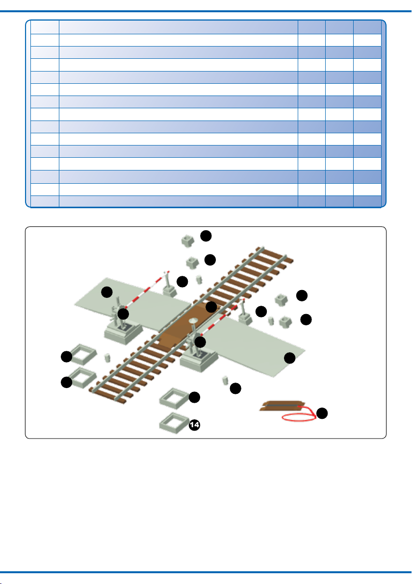
1.3 Packungsinhalt überprüfen
Kontrollieren Sie den Lieferumfang auf
Vollständigkeit (siehe Tabelle und Abb. 1):
2
1.3 Checking the package contents
Check the contents of the package for complete-
ness (see table and g. 1):
Pos.
Bezeichnung / Description
H0 TT N
1 Bahnschranke mit Antrieb / Barrier with drive unit 2 2 2
2 Verkehrsschild mit Mast / Trac sign with mast 2 2 2
3 Andreaskreuz mit Mast / St. Andrew‘s cross with mast 2 2 2
4 Warnbake mit Mast / Beacon with mast 12 12 12
5 Rampe / Ramp 2 4 2
6 Rampenfuß / Ramp socket 4 - 7 Gleiszwischenstück / Additional inll 1 1 1
8 Gleiszwischenstück mit Kabel / Additional inll with cable 1 - -
9 Befestigungsring für Antrieb / Attachment ring for drive 2 2 2
10 Schrankenbaumwiderlager / Barrier support 2 2 2
11 Oberes Sockelstück für Widerlager / Upper socket part for barrier support 2 - 12 Unteres Sockelstück für Widerlager / Lower socket part for barrier support 2 - 13 Oberes Sockelstück für Schranke / Upper socket part for barrier 2 - 14 Unteres Sockelstück für Schranke / Lower socket part for barrier 2 - -
Abb. 1
10
5
1
13
14
13
5100
14
2. Einleitung
2.1 Vorbild
Zur Sicherung von Bahnübergängen durch Bahnschranken wurden seit jeher Schrankenwärter
eingesetzt. Die Schranken wurden über Seilzüge
durch den Schrankenwärter fernbedient. Bis in die
heutige Zeit ist dies bei der Bahn unverändert.
Allerdings werden die Schrankenwärter immer
weniger, da alle handbetätigten Bahnübergänge
nach und nach durch moderne Lichtzeichenanlagen ersetzt werden.
11
12
11
7
1
10
12
5
6
8
Fig. 1
2. Introduction
2.1 Prototype
To secure level crossings by crossing barriers
gate keepers are appointed in the past and even
today. These barriers are remote-operated manually by the gate keeper with cables.
These level crossings are still used today.
But the gate keepers are replaced more and more
by modern trac light systems.
3

2.2 Modell
Das Viessmann-Modell einer vollautomatischen Bahnschranke gibt vorbildgerecht die Funktionen des Originals wieder und ist ein Schmuckstück auf Ihrer
Anlage. Die beiden Schrankenbäume werden durch je
einen Unterur-Kompaktantrieb angetrieben, welche
diese vorbildgerecht langsam heben und senken.
Da jeder Schrankenbaum einzeln angetrieben wird,
kann die Schranke individuell eingesetzt und jeder
Betriebssituation angepasst werden. Übergänge im
Winkel von 45°, mehrgleisige Übergänge oder der
Einsatz von 4 Schrankenbäumen als gegenschlägige
Schranke für sehr breite Straßen sind kein Problem
(Widerlager sind nicht notwendig, Schrankenbäume
stehen ohne Stütze in der Endlage waagerecht).
Ein Gleisfüllstück sowie Rampen auf das Gleisniveau
liegen bei. Die beiliegenden Verkehrsschilder sind bereits fertig bedruckt. Für den Einsatz der Schranke in
den Epochen II – III sind an den Andreaskreuzen und
den Warnbaken Bruchkanten angebracht, um diese
den damaligen Straßenverkehrsvorschriften entsprechend kürzen zu können.
2.2 The model
The Viessmann model of a fully automatic crossing barrier shows the prototypical functions of the
original and is an eye-catcher on your layout.
Driven by an underoor-drive unit, the beams rise
and lower with a prototypical slow movement.
Because each beam is driven separately the barrier
can be installed according to any operating situation.
Crossings with an angle of 45°, multiple-track crossings or the use of 4 crossing beams working in opposite direction from each other for very wide streets
are no problem (barrier supports are not necessary,
the beams remain horizontal in the end position
without support).
An additional inll as well as ramps for the track
level are included. The included trac signs are
already printed. Breaking edges are provided on
the St. Andrew’s crosses and the beacons, so that
it is possible to shorten the signs appropriately to
t the trac regulations of epochs II – III.
3. Funktionskontrolle
Führen Sie vor der Montage eine Funktionskontrolle durch. Nehmen Sie die Bahnschranken vorsichtig aus der Verpackung.
Schließen Sie dann das gelbe Kabel an einen Pol
eines 16 V-Modellbahntransformators (AC ~/DC
=) an, z. B. Viessmann Art.-Nr. 5200.
Verbinden Sie abwechselnd jeweils ein blaues
Kabel mit dem anderen Pol des Trafos. Schließen
Sie niemals die blauen Kabel gleichzeitig an.
Das kann zur Zerstörung des Antriebs führen.
Blau mit roter Markierung:
Schranken önen sich.
Blau mit grüner Markierung:
Schranken schließen sich.
4. Einbau
1. Zeichnen Sie die Positionen der Bohrungen
für die Schranken und die Widerlager mit
Hilfe der in Abb. 2 abgebildeten Schablone an.
Die Mittelpunkte der Bohrungen müssen einen
Abstand von 58,6 mm (H0), 50,0 mm (TT) bzw.
46 mm (N) haben.
2. Bohren Sie an den angezeichneten Stellen jeweils zwei Löcher mit einem Durchmesser von
13 mm für die Schrankenantriebe und 4 mm
(H0) bzw. 1 mm (TT, N) für die Widerlager.
3. Stecken Sie die Schranken mit dem Antrieb
von oben durch die Bohrungen (Abb. 3).
4. Schieben Sie die Befestigungsringe von un-
ten so auf die Antriebe auf, dass die Rastnasen
4
3. Function check
Check all functions before installation.
Carefully take the barriers out of the packaging.
Connect the yellow wire to one of the terminals of
a 16 V-transformer (AC ~/DC =), e. g. Viessmann
item-No. 5200.
Then alternately connect the blue cables with the
other terminal. Never connect the blue cables
at the same time to the transformer. This may
destroy the drive unit.
Blue with red marker:
Barriers will be raised.
Blue with green marker:
Barriers will be lowered.
4. Mounting
1. Mark the positions for the holes to be drilled for
the barriers and the barrier supports as
shown in the template in g. 2. The centre points
of the holes must have a distance of 58,6 mm
(H0), 50 mm (TT) or 46 mm (N) to each other.
2. Drill two holes at the marked positions with a
diameter of 13 mm for the barrier drives and 4
mm (H0) resp. 1 mm (TT, N) for the barrier
supports.
3. Insert the barrier with the drive from above
through the large holes (g. 3).
4. Slide the attachment rings onto the drives so
that the snap tabs sit at an angle of 90° against
the ribbing on the housing of the drive (g. 3)

um 90° zu der Rielung am Gehäuse der Antriebe verdreht sind (Abb. 3). Drehen Sie den
Ring so, dass die Nasen in der Rielung des
Antriebsgehäuses für einen festen Halt sorgen.
Halten Sie dabei die Sockel der Bahnschranke
von oben fest.
Abb. 2
H0: 58,6 mm
TT: 50 mm
N: 46 mm
and are rmly arrested.
During this process you should hold down the
base of the barrier form above.
Fig. 2
Widerlager
barrier support
13 mm
Schranke
barrier
N + TT: 1 mm
Abb. 3
Achtung:
Fassen Sie die Schran-
ken nie am Baum oder
Lager an, sondern nur
an der Bodenplatte bzw.
dem Antriebszylinder,
wenn Sie sie ausbauen
wollen!
Attention
Never touch the barrier itself. If you
have to remove the model, do not
pull the model. Carefully take the
drive unit instead and push it up.
Abb. 4
blau mit roter Markierung
blue with red marker
bla u mit grüner Markierung
blue with green marker
5100
5100
5. Stecken Sie die Widerlager in die entsprechenden Bohrungen ein.
6. Kleben Sie das Gleisfüllstück bzw. auf die
Schwellen zwischen den Schienenprolen im
Bereich des Bahnüberganges auf.
Bei Zweileitergleisen (Fleischmann, Trix,
Roco, Peco, Lima usw.) verwenden Sie bitte
das Gleiszwischenstück ohne Metallstreifen
und Anschlusskabel (7).
H0: 4 mm
H0: 5 mm
H0: 5,5 mm
Schranke öffnen
open barrier
Schranke schließen
close barrier
Gemeinsamer Mittelpunkt der Antriebsspulen
gelb
common pole for the drive coils
yellow
Kontakt für Blinkelektronik der Andreaskreuze
rot
contact for blinker unit of St. Andrew´s crosses
red
Kontakt für Blinkelektronik der Andreaskreuze
rot
contact for blinker unit of St. Andrew´s crosses
red
11
90°
12
5. Insert the barrier supports into the according
holes.
6. Glue the additional inlls resp. on the
sleeper between the tracks in the section of the
level crossing.
For 2 rail tracks (Fleischmann, Trix, Roco,
Peco, Lima etc.) please use the additional inll
without metalband and without wire (7).
13 mm
Fig. 3
Fig. 4
5

Für Mittelleitergleise (nur H0: Märklin C, M und
K, Trix Express) verwenden Sie bitte das Gleiszwischenstück mit Metallstreifen und rotem Anschlusskabel (8). Das rote Anschlusskabel führen
Sie zwischen den Schwellen nach unten (eventuell
zuvor ein Loch bohren) und schließen es am Mittelleiter-Fahrstromanschluss (rot bei Märklin) an.
Zum Erstellen breiterer oder mehrgleisiger Übergänge für H0 gibt es unter der Art.-Nr. 5101 (Zweileiter) und Art.-Nr. 5102 (Mittelleiter) einen Ergänzungssatz mit jeweils einem entsprechenden
Gleiszwischenstück. Die Rampen
Auahrt für die Modellautos auf das Gleisniveau.
dienen als
For 3 rail tracks (only H0: Märklin C, M and
K, Trix Express), please use the additional inll
with metalband and with red wire (8).
Lead the red connecting wire between the
sleepers to the lower side of the layout (rst
drill a hole). Then connect it to the neutral conductor (Märklin: red).
For realizing wider level crossings or over several
tracks you may purchase additional inlls, itemNo. 5101 (2 rail track) and item-No. 5102
(3 rail track). The ramps are used as drive-up
for cars on the level crossing.
5. Anschluss
Schließen Sie die Schranken gemäß Abb. 5 oder
6 an. Zur Bedeutung der Kabelfarben siehe Abb.
4. Für den zuggesteuerten Betrieb benötigen Sie
Schaltgleise oder -kontakte (z. B. Viessmann Art.Nr. 6840 und 6841).
Bei zweigleisigem Betrieb ist ein elektronisches Relais Art.-Nr. 5552 erforderlich. Dadurch wird erreicht,
dass bei gleichzeitigem Überqueren des Bahnüberganges von 2 entgegenkommenden Zügen die
Schranken erst wieder geönet werden, wenn beide
Züge den Bahnübergang verlassen haben.
Die Antriebe der H0-Bahnschranke (Art.-Nr. 5100)
verfügen über jeweils einen zusätzlichen Schaltkontakt. Diese können Sie nutzen, um z. B. eine Blinkelektronik für Andreaskreuze (z. B. Art.-Nr. 5835) zu
steuern. Hierzu führen Sie eine der beiden Stromversorgungsleitungen der Blinkelektronik über den Kontakt eines der beiden Antriebe.
Gleichstrombetrieb: Schließen Sie die gelben Kabel
an den Minuspol des Trafos an.
6. Digitale Ansteuerung
Die Viessmann Bahnschranken lassen sich auch mit
einem Digitalsystem ansteuern. Schließen Sie die Antriebe der Bahnschranken dazu an einen Magnetartikeldecoder, z. B. Art.-Nr. 5211 (Märklin-Motorola) oder
Art.-Nr. 5280 (DCC) wie eine Weiche oder ein Signal
an. Achten Sie darauf, neben den blauen auch das
gelbe Kabel für die Stromversorgung anzuschließen.
5. Connection
Connect the barriers as shown in g. 5 or 6. For
the meaning of the cable colours refer to g. 4.
To control the beams by trains, you need switching tracks or -contacts (e. g. Viessmann item-No.
6840 and 6841).
An electronic relay item-No. 5552 is required for
two track operation. This is necessary when 2
trains are approaching each other and crossing at
the same time. The beams do not open until both
trains have left the level crossing.
Each drive unit of the H0-crossing barrier (itemNo. 5100) includes an additional switching contact. They can be used to control the blinking elec-
tronics of warning lights (e. g. item-No. 5835). To
use this function, please connect one of the wires
for the electric current of the blinker unit with the
contact of one of the drive units.
Direct current: Connect both yellow cables to the
negative pole of the transfomer.
6. Digital control
Of course crossing barriers can be controlled by using a digital system. For digital control of the beams,
connect the drive units to a digital decoder such as
item-No. 5211 (Märklin-Motorola) or item-No. 5280
(DDC) in the same way as a point or a signal. Remind, that you have to connect not only the blue cables but also the yellow cables for power supply!
6.1 Wichtiger Hinweis für digitales Schalten
Der Viessmann Bahnschrankenantrieb benötigt
für den ordnungsgemäßen Betrieb eine Schaltspannung von mindestens 16 Volt.
Verwenden Sie ausschließlich Magnetartikeldecoder mit separater Schaltspannungseinspeisung
(z. B. alle Viessmann Magnetartikeldecoder).
Benutzen Sie einen ausreichend starken Trafo (z. B.
Viessmann Art.-Nr. 5200 oder 5201) in Verbindung
mit dem Viessmann Powermodul Art.-Nr. 5215/5225.
6
6.1 Important information for digital switching
The Viessmann level crossing drive requires a
switching voltage of minimum 16 volt for proper
operation.
Therefore you should use digital decoders with
a separate switching voltage input only (e. g. all
Viessmann digital decoders).
For power supply, use a powerful transformer (e. g.
Viessmann item-No. 5200 or 5201) combined with
the Viessmann power module item-No. 5215/5225.

Abb. 5
driving direction
braun
gelb
blau (rote Markierung)
grün
rot
blau (grüne Markierung)
openclose
/ yellow
/ blue (red marker)
/ brown
/ red
/ green
open close
min. 1 train length
/ blue (green marker)
Fahrtrichtung
16 V ~
öffnen öffnenschließenschließen
mind. 1 Zuglänge
driving direction
Elektr. Relais 5552
Viessmann
braun
gelb
rot
grün
blau
blau
blau
blau
blau
blau
blau (rote Markierung)
blau (grüne Markierung)
Schranke auf
Schranke zu
open
close
/ yellow
brown
/ green
/ red
open
close
min. 1 train length
blue
blue
blue
blue
blue
blue
/ blue (red marker)
/ blue (green marker)
open barrier
close barrier
Fahrtrichtung
Fahrtrichtung
driving direction
16 V ~
öffnen
öffnenschließen
schließen
mind. 1 Zuglänge
Fig. 5
Abb. 6
7. Montage der Verkehrsschilder
1. Zur Verwendung der Schilder in den Epochen II und
III die Warnbaken und die Andreaskreuze an
den vorgegebenen Bruchkanten auf der Rückseite
der Schilder kürzen. Mit scharfem Messer vorritzen!
2. Andreaskreuze (bei H0 auch die Warnbaken) mit
handelsüblichem Polystyrolkleber an die entsprechenden Masten kleben. Beachten Sie hierbei,
dass in den Epochen II und III das Andreaskreuz
um 90° gedreht am Mast befestigt wurde,
7. Installing the trafc signs
1. To use the signs in epoch II and III, rst shorten
the beacons and the St. Andrew’s crosses
at the specied breaking edges on the rear
of the signs. If necessary, rst cut an indentation with a sharp knife!
2. Glue the St. Andrew’s crosses with standard
polystyrene glue to their respective masts. Please
note that in epochs II and III the St. Andrew’s
cross was attached at a 90° angle on the
Fig. 6
7

wobei die kurzen Schenkel nach unten zeigten.
3. Bohren Sie an den dafür vorgesehenen Stellen Löcher mit dem in der Abb. 7 angegebenen
Durchmesser und montieren Sie die Schilder in
der richtigen Reihenfolge (siehe Abb. 7).
4. Der Regelabstand zwischen den Warnbaken beträgt beim Vorbild 80 m (H0 92 cm, TT 67 cm, N 50
cm). Wenn die örtlichen Gegebenheiten es erfordern, sind aber auch kürzere Abstände erlaubt.
5. Bei beengten Platzverhältnissen können Sie
die dreistreige Warnbake mit einem Messer
vom eigenen Mast abtrennen und unten an den
Mast des Verkehrsschildes kleben.
mast, with the short shanks pointing downwards.
3. Drill holes as shown in g. 7 at the marked po-
sitions and install the signs in the correct se-
quence (see g. 7).
4. The standard distance between the beacons in
reality is 80 m (H0 92 cm, TT 67 cm, N 50 cm).
Shorter distances are also permitted when the
local situation requires it.
5. As an additional measure the beacon
with
the three strips may be separated from its mast
and glued at the bottom onto the mast of the
rst warning sign .
Abb. 7
H0:
4 mm
TT, N:
1,5 mm
3
8. Technische Daten
Betriebsspannung: 16 V = / ~
Stromaufnahme
(im Schaltmoment, ca. 0,1 s): 0,7 A
Max. Belastbarkeit des Fahrstromkontaktes: 2 A
Entsorgen Sie dieses Produkt nicht über
den (unsortierten) Hausmüll, sondern führen Sie es der Wiederverwertung zu.
Änderungen vorbehalten. Keine Haftung für Druckfehler
und Irrtümer.
Die aktuelle Version der Anleitung nden Sie auf der
Viessmann Homepage unter der Artikelnummer.
Modellbauartikel, kein Spielzeug! Nicht geeignet für Kinder
DE
unter 14 Jahren! Anleitung aufbewahren!
Model building item, not a toy! Not suitable for children
EN
under the age of 14 years! Keep these instructions!
Ce n’est pas un jouet. Ne convient pas aux enfants de
FR
moins de 14 ans ! C’est un produit décor! Conservez cette
notice d’instructions!
Não é um brinquedo!Não aconselhável para menores de
PT
14 anos. Conservar a embalagem.
Zum Bahnübergang
to the level crossing
44 4
Fig. 7
2
8. Technical data
Operating voltage: 16 V = / ~
Peak inrush current (for approx. 0,1 s): 0,7 A
Max. contact load of
the track control contact: 2 A
Do not dispose this product through (unsorted)
general trash, but supply it to the recycling.
Subject to change without prior notice. No liability for mistakes and printing errors.
The latest version of the manual can be looked up at the
Viessmann homepage using the item-No.
Modelbouwartikel, geen speelgoed! Niet geschikt voor
NL
kinderen onder 14 jaar! Gebruiksaanwijzing bewaren!
Articolo di modellismo, non è un giocattolo! Non adatto
IT
a bambini al di sotto dei 14 anni! Conservare instruzioni
per l’uso!
Artículo para modelismo ¡No es un juguete! No
ES
recomendado para menores de 14 años! Conserva las
instrucciones de servicio!
Modelltechnik GmbH
Bahnhofstraße 2a
D - 35116 Hatzfeld-Reddighausen
www.viessmann-modell.de
Made in Europe
98179
Stand 07
02/2018
Ho/Me
 Loading...