

Page 1
Bedienungsanleitung
Operation Manual
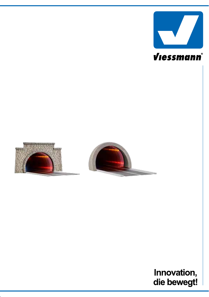
H0 Straßentunnel, mit
LED Spiegeleffekt und
Tiefenwirkung
H0 Road tunnel, with LED
mirroring- and depth effect
5097 klassisch / classic
5098 modern / modern
5097 5098
1. Wichtige Hinweise / Important information ........................................................ 2
2. Einbau / Mounting ............................................................................................. 2
3. Anschluss / Connection ..................................................................................... 3
4. Gewährleistung / Warranty ................................................................................ 4
5. Technische Daten / Technical data .................................................................... 5
Page 2
DE EN
1. Wichtige Hinweise
Bitte lesen Sie vor der ersten Anwendung des Produktes
bzw. dessen Einbau diese Bedienungsanleitung aufmerksam durch. Bewahren Sie diese auf, sie ist Teil des
Produktes.
1.1 Sicherheitshinweise
Vorsicht:
Verletzungsgefahr!
Aufgrund der detaillierten Abbildung des Originals bzw.
der vorgesehenen Verwendung kann das Produkt Spitzen, Kanten und abbruchgefährdete Teile aufweisen. Für
die Montage sind Werkzeuge nötig.
Stromschlaggefahr!
Die Anschlussdrähte niemals in eine Steckdose einführen! Verwendetes Versorgungsgerät (Transformator,
Netzteil) regelmäßig auf Schäden überprüfen. Bei Schäden am Versorgungsgerät dieses keinesfalls benutzen!
Ausschließlich nach VDE/EN gefertigte Modellbahntransformatoren verwenden!
Alle Anschluss- und Montagearbeiten nur bei abgeschal
teter Betriebsspannung durchführen!
Stromquellen unbedingt so absichern, dass es bei einem
Kurzschluss nicht zum Kabelbrand kommen kann.
1.2 Das Produkt richtig verwenden
Dieses Produkt ist bestimmt:
- Zum Einbau in Modelleisenbahnanlagen und Dioramen.
- Zum Anschluss an einen Modellbahntransformator
(z. B. Art. 5200) bzw. an eine Modellbahnsteuerung mit
zugelassener Betriebsspannung.
- Zum Betrieb in trockenen Räumen.
Jeder darüber hinausgehende Gebrauch gilt als nicht bestimmungsgemäß. Für daraus resultierende Schäden haftet
der Hersteller nicht.
1.3 Packungsinhalt überprüfen
Kontrollieren Sie den Lieferumfang auf Vollständigkeit:
- Straßentunnel klassisch bzw. modern aus Steinkunst
- Montierte optische Einheit
- Straßenplatte aus Steinkunst, L 18 cm
- Anleitung
1. Important information
Please read this manual completely and attentively before
using the product for the first time. Keep this manual. It is
part of the product.
1.1 Safety instructions
-
1.2 Using the product for its correct purpose
This product is intended:
- For installation in model train layouts and dioramas.
- For connection to an authorized model train transformer
- For operation in dry rooms only.
Using the product for any other purpose is not approved
and is considered inappropriate. The manufacturer is not
responsible for any damage resulting from the improper
use of this product.
1.3 Checking the package contents
Check the contents of the package for completeness:
- Road tunnel, classic resp. modern made of Stone Art
- Mounted optical unit
- Street plate made of Stone Art, L 18 cm
- Manual
Caution:
Risk of injury!
Due to the detailed reproduction of the original and the
intended use, this product can have peaks, edges and
breakable parts. Tools are required for installation.
Electrical hazard!
Never put the connecting wires into a power socket!
Regularly examine the transformer for damage. In case
of any damage, do not use the transformer.
Only use VDE/EN tested special model train transformers for the power supply!
Make sure that the power supply is switched off when
you mount the device and connect the cables!
The power sources must be protected to avoid the risk
of burning cables.
(e. g. item 5200) or a digital command station.
2. Einbau
1. Legen Sie die Straße auf eine stabile horizontale Oberfläche.
2. Nehmen Sie die optische Einheit vorsichtig aus der
Verpackung.
Vorsicht!
Fassen Sie die optische Einheit nur mit einem Textilhandschuh oder einem fettfreien Brillenputztuch an, um
Fingerabdrücke und Kratzer zu vermeiden!
2
2. Mounting
1. Place the street onto a stable horizontal surface.
2. Carefully remove the optical unit from the package.
Caution!
Touch the optical unit only with textile gloves or a greaseless lens cleaning tissue in order to avoid fingerprints
and scratches!
Page 3

3. Versehen Sie die quadratischen Einkerbungen der
Straßenplatte mit etwas Klebstoff (Abb. 1).
3. Apply some glue to the square notches of the street
plate (fig. 1).
Abb. 1
4. Platzieren Sie die optische Einheit auf der Straßenplatte
(Abb. 2). Achten Sie darauf, dass die optische Einheit
so platziert wird, dass die Reflexion der Linien durchlaufend übereinstimmt (Abb. 3). Einbauseite beachten!
Abb. 2
Spiegelseite
Mirror side
Transparente Seite
Transparent side
Fig. 1
4. Place the optical unit onto the street plate (fig. 2). Make
sure to place the optical unit in a way that the reflection
of the lines fully coincides with the lines on the road (fig.
3). Observe the mounting side!
Fig. 2
Abb. 3
Fig. 3
3
Page 4

5. Versehen Sie die Vertiefung der Rückseite des Tunnelportals sowie die Auflagefläche des Portals auf der
Straßenplatte mit einem handelsüblichen Bastelkleber
(Abb. 4).
Abb. 4
5. Apply some commercially available adhesive to the
recess of the tunnel portal’s rear side as well as to the
contact surface between portal and street plate (fig. 4).
Fig. 4
6. Platzieren Sie das Tunnelportal vorsichtig auf die Vorderseite der optischen Einheit. Achten Sie darauf, dass
Sie die bereits verklebte Einheit nicht bewegen!
7. Nach Trocknung des Klebers, platzieren Sie die montierte Straßenplatte mit optischer Einheit und Tunnelportal
an der gewünschten Stelle Ihrer Anlage und markieren
die Position des Ausführungslochs der Anschlusskabel.
8. Zur Bohrung des Lochs entfernen Sie zunächst den
Straßentunnel. Bohren Sie ein Loch Ø 2 mm an der
markierten Position. Führen Sie die Anschlusskabel von
oben durch die Bohrung und platzieren den Straßentunnel final.
3. Anschluss
Schließen Sie die LED-Beleuchtung des Straßentunnels
an den Lichtausgang eines Modellbahntransformators
(z. B. Art. 5200) an (Abb. 5).
Gleichspannung: Verbinden Sie die Diode (rotes Bauteil
mit schwarzer Markierung) mit dem Plus-Pol des Netzteils,
den Widerstand mit dem Minus-Pol.
Wechselspannung: Bei Betrieb mit Wechselspannung
kann es zu leichtem Flackern kommen. Daher empfehlen
wir den Betrieb mit dem Viessmann-Powermodul Art. 5215.
Ein Powermodul ist ausreichend für ca. 100 LED-Leuchten
oder -Strahler. Verbinden Sie das Anschlusskabel mit der
Diode mit der braunen Anschlussbuchse, das Anschlusskabel mit dem Widerstand mit der roten Anschlussbuchse.
6. Carefully place the tunnel portal onto the front side of
the optical unit. Make sure not to move the unit which
has already been sealed!
7. Once the adhesive is dry, take the mounted street plate
with optical unit and tunnel portal to the desired spot
on your layout and mark the position of the bore for the
connection cables.
8. To drill the hole, remove the road tunnel first. Then drill
a hole of 2 mm diam. at the marked position. Insert the
connection cables from above through the bore and
bring the road tunnel into its final position.
3. Connection
Connect the LED lighting of the street tunnel to the lighting
power output of a model train transformer (e. g. item 5200)
or power supply as shown in fig. 5.
DC voltage: Connect the diode (red part with black mark)
with the plus pole of the power supply, the resistor with
the minus pole.
AC voltage: Operation with AC voltage could cause some
flickering. We recommend to use the Viessmann power
module, item 5215, which is sufficient for approx. 100
LED-lamps or -reflectors. Connect the cable to the diode
with the brown output socket, the resistor with the red output socket of the power module.
4
Page 5

Abb. 5
Straßentunnel
Road tunnel
Art. / Items
5097 / 5098
z. B. / e. g.: 5200
Fig. 5
braun / brown
gelb / yellow
150 Ohm
Lichttransformator
Primär
230 V~
Primär 230 V 50 - 60 Hz
Sekundär 52 VA max. 3,25 A
Nur für trockene Räume
IP 40 ta 25°C
Gefertigt nach
VDE 0570
EN 61558
5200
Sekundär
0-10-16 V~
16 V
10 V
0 V
4. Gewährleistung
Jeder Artikel wurde vor Auslieferung auf volle Funktionalität
geprüft. Der Gewährleistungszeitraum beträgt 2 Jahre ab
Kaufdatum. Tritt in dieser Zeit ein Fehler auf und Sie finden
die Fehlerursache nicht, nehmen Sie bitte Kontakt mit uns
auf (service@viessmann-modell.com).Senden Sie uns
den Artikel zur Kontrolle bzw. Reparatur bitte erst nach
Rücksprache zu. Wird nach Überprüfung des Artikels ein
Herstell- oder Materialfehler festgestellt, wird er kostenlos
instandgesetzt oder ausgetauscht. Von der Gewährleistung
und Haftung ausgeschlossen sind Beschädigungen des
Artikels sowie Folgeschäden, die durch unsachgemäße
Behandlung, Nichtbeachten der Bedienungsanleitung, nicht
bestimmungsgemäßen Gebrauch, eigenmächtigen Eingriff,
bauliche Veränderungen, Gewalteinwirkung, Überhitzung
u. ä. verursacht werden.
gelb / yellow
braun / brown
4. Warranty
Each model is tested as to its full functionality prior to delivery. The warranty period is 2 years starting on the date
of purchase. Should a fault occur during this period please
contact our service department (service@viessmannmodell.com). Please send the item to the Viessmann service department for check and repair only after consultation. If we find a material or production fault to be the cause
of the failure the item will be repaired free of charge or
replaced. Expressively excluded from any warranty claims
and liability are damages of the item and consequential
damages due to inappropriate handling, disregarding the
instructions of this manual, inappropriate use of the model,
unauthorized disassembling, construction modifications
and use of force, overheating and similar.
5
Page 6

Viessmann
hnik GmbH
www.viessmann-modell.de
5. Technische Daten
Betriebsspannung: 10 – 16 V AC ~
(mit und ohne 5215 Powermodul)
14 – 24 V DC =
13 – 24 V Digitalsignal
Stromaufnahme: ca. 10 mA
Einbautiefe Tunnelportal: 2,5 cm
Maße: Länge Tunnelportal incl. Straße 18 cm,
Breite Klassisches Portal 16,5 cm,
Breite modernes Portal 12 cm,
Höhe klassisches Portal 10 cm,
Höhe modernes Portal 7,6 cm
5. Technical data
Operating voltage: 10 – 16 V AC ~
(with and without 5215 power modul)
14 – 24 V DC =
13 – 24 V digital signal
Operating current: ca. 10 mA
Mounting depth tunnel portal: 2,5 cm
Dimensions: length tunnel portal incl. street 18 cm,
width classical portal 16,5 cm,
width modern portal 12 cm,
height classical portal 10 cm,
height modern portal 7,6 cm
Entsorgen Sie dieses Produkt nicht über den
(unsortierten) Hausmüll, sondern führen Sie
es der Wiederverwertung zu.
Änderungen vorbehalten. Keine Haftung für Druckfehler
und Irrtümer.
Die aktuelle Version der Anleitung finden Sie auf der Viessmann Homepage unter der Artikelnummer.
Modellbauartikel, kein Spielzeug! Nicht geeignet für Kinder
DE
unter 14 Jahren! Anleitung aufbewahren!
Model building item, not a toy! Not suitable for children
EN
under the age of 14 years! Keep these instructions!
Ce n’est pas un jouet. Ne convient pas aux enfants de
FR
moins de 14 ans ! C’est un produit décor! Conservez cette
notice d’instructions!
Não é um brinquedo!Não aconselhável para menores de
PT
14 anos. Conservar a embalagem.
Modelltec
Bahnhofstraße 2a
D - 35116 Hatzfeld-Reddighausen
info@viessmann-modell.com
6
Do not dispose of this product through (unsorted)
domestic waste, supply it to recycling instead.
Subject to change without prior notice. No liability for
mistakes and printing errors.
You will find the latest version of the manual on the Viessmann website using the item number.
Modelbouwartikel, geen speelgoed! Niet geschikt voor
NL
kinderen onder 14 jaar! Gebruiksaanwijzing bewaren!
Articolo di modellismo, non è un giocattolo! Non adatto
IT
a bambini al di sotto dei 14 anni! Conservare instruzioni
per l’uso!
Artículo para modelismo ¡No es un juguete! No
ES
recomendado para menores de 14 años! Conserva las
instrucciones de servicio!
85884
Stand 01/sw
Made in Europe
05/2019
Ho/Kf
 Loading...