

Page 1
Bedienungsanleitung
Innovation,
AC~DC
=
Operation Manual
5094
H0 Bogenampel mit
Fußgängerampel
und LEDs, 2 Stück
H0 Arc traffic light with
pedestrian signal and LEDs,
2 pieces
5095
H0 Verkehrsampel mit
Fußgängerampel und LEDs,
5094
2 Stück
5095
H0 Traffic light with
pedestrian signal and LEDs, 2 pieces
1. Wichtige Hinweise / Important information ........................................................ 2
2. Einleitung / Introduction ..................................................................................... 2
3. Einbau / Mounting ............................................................................................. 3
4. Anschluss / Connection ..................................................................................... 4
5. Betrieb / Operation ............................................................................................ 4
6. Fehlersuche und Abhilfe / Trouble-shooting ...................................................... 8
7. Gewährleistung / Warranty ................................................................................ 8
8. Technische Daten / Technical data .................................................................... 8
die bewegt!
Page 2
DE EN
1. Wichtige Hinweise
Bitte lesen Sie vor der ersten Anwendung des Produktes
bzw. dessen Einbau diese Bedienungsanleitung aufmerksam durch. Bewahren Sie diese auf, sie ist Teil des
Produktes.
1.1 Sicherheitshinweise
Vorsicht:
Verletzungsgefahr!
Aufgrund der detaillierten Abbildung des Originals bzw.
der vorgesehenen Verwendung kann das Produkt Spitzen, Kanten und abbruchgefährdete Teile aufweisen. Für
die Montage sind Werkzeuge nötig.
Stromschlaggefahr!
Die Anschlussdrähte niemals in eine Steckdose einführen! Verwendetes Versorgungsgerät (Transformator,
Netzteil) regelmäßig auf Schäden überprüfen. Bei Schäden am Versorgungsgerät dieses keinesfalls benutzen!
Alle Anschluss- und Montagearbeiten nur bei abgeschal
teter Betriebsspannung durchführen!
Ausschließlich nach VDE/EN gefertigte Modellbahntransformatoren verwenden!
Stromquellen unbedingt so absichern, dass es bei einem
Kurzschluss nicht zum Kabelbrand kommen kann.
1.2 Das Produkt richtig verwenden
Dieses Produkt ist bestimmt:
- Zum Einbau in Modelleisenbahnanlagen und Dioramen.
- Zum Anschluss an einen Modellbahntransformator
(z. B. Art. 5200) bzw. an eine Modellbahnsteuerung mit
zugelassener Betriebsspannung.
- Zum Betrieb in trockenen Räumen.
Jeder darüber hinausgehende Gebrauch gilt als nicht bestimmungsgemäß. Für daraus resultierende Schäden haftet
der Hersteller nicht.
1.3 Packungsinhalt überprüfen
Kontrollieren Sie den Lieferumfang auf Vollständigkeit:
- 2 Ampeln
- 2 Halteringe
- Elektronikbaugruppe
- 100-Ohm-Widerstand als Kabelbrücke für Nachtbetrieb
- Anleitung
1. Important information
Please read this manual completely and attentively before
using the product for the first time. Keep this manual. It is
part of the product.
1.1 Safety instructions
-
1.2 Using the product for its correct purpose
This product is intended:
- For installation in model train layouts and dioramas.
- For connection to an authorized model train transformer
- For operation in dry rooms only.
Using the product for any other purpose is not approved
and is considered inappropriate. The manufacturer is not
responsible for any damage resulting from the improper
use of this product.
1.3 Checking the package contents
Check the contents of the package for completeness:
- 2 Traffic lights
- 2 Retaining rings
- Electronic control
-
- Manual
Caution:
Risk of injury!
Due to the detailed reproduction of the original and the
intended use, this product can have peaks, edges and
breakable parts. Tools are required for installation.
Electrical hazard!
Never put the connecting wires into a power socket!
Regularly examine the transformer for damage. In case
of any damage, do not use the transformer.
Make sure that the power supply is switched off when
you mount the device and connect the cables!
Only use VDE/EN tested special model train transformers for the power supply!
The power sources must be protected to avoid the risk
of burning cables.
(e. g. item 5200) or a digital command station.
100 Ohm resistor as wiring bridge for night-time operation
2. Einleitung
Originalgetreue Nachbildung einer Verkehrsampel im Stil
der Epochen III – VI mit 2 Ampeln zur Darstellung eines
Fußgänger-Überwegs mit Lichtzeichenanlage. Beide Ampeln verfügen über je eine rote, gelbe und grüne LED für
den Straßenverkehr und je eine rote und grüne LED für
Fußgänger. Die Ampeln verfügen jeweils über einen Messingmast mit Patentsteckfuß für eine besonders einfache
Montage und wartungs- und flackerfreie LED-Beleuchtung.
Über die beiliegende Elektronik werden beide Ampeln in
einem festen Wechselrhythmus automatisch gesteuert.
2
2. Introduction
Prototypical model of a traffic light with two sets of lights
for modelling a pedestrian crossing with traffic lights suitable for eras III through VI. Both sets of lights consist of
one red, amber and green LED for the motorized traffic
and one each red and green LED for the pedestrians. Patented base socket for particularly easy mounting. Maintenance free and flicker-free due to LED light sources.
The enclosed electronics control both sets of lights in a
predetermined alternating rhythm. The duration of the
green respectively red phases may be varied. This can be
Page 3
Optional ist die Änderung der Dauer der Grün- und Rotphasen möglich, z. B. über das Viessmann Zeitrelais Art. 5207.
Da die Ansteuerung der Ampel in Multiplextechnik erfolgt,
genügen drei Zuleitungen.
An den Enden der Zuleitungen befinden sich Widerstände,
die nicht entfernt werden dürfen. Sie dienen auch zum Anschluss der Ampeln an das Steuermodul.
In Verbindung mit Art. 5096 kann eine komplette Kreuzung (2 Straßen) mit Ampeln ausgestattet werden. Die
Ansteuerung erfolgt über die in Art. 5094/5095 enthaltene
Elektronik. Für eine Kreuzung (2 Straßen) werden 2 x Art.
5094/5095 und 1 x Art. 5096 benötigt.
accomplished by using a Viessmann time relay, item 5207.
The traffic lights are controlled with the proven multiplex
technology. Therefore, only three wires are required.
The resistors are attached to the ends of these wires
which may not be removed. They serve for the proper
connection of the traffic lights to the control module.
Together with item 5096 a complete crossover (2 streets)
can be equipped with traffic lights. It is controlled by the
electronics of item 5094/5095. For a full two-street intersection 2 x item 5094/5095 and 1 x item 5096 are required.
3. Einbau/Montage
Achtung:
Artikel enthält abbruchgefährdete Kleinteile, Ampel beim
Einstecken nur am unteren Teil des Mastes anfassen.
Montieren Sie die Ampel wie folgt:
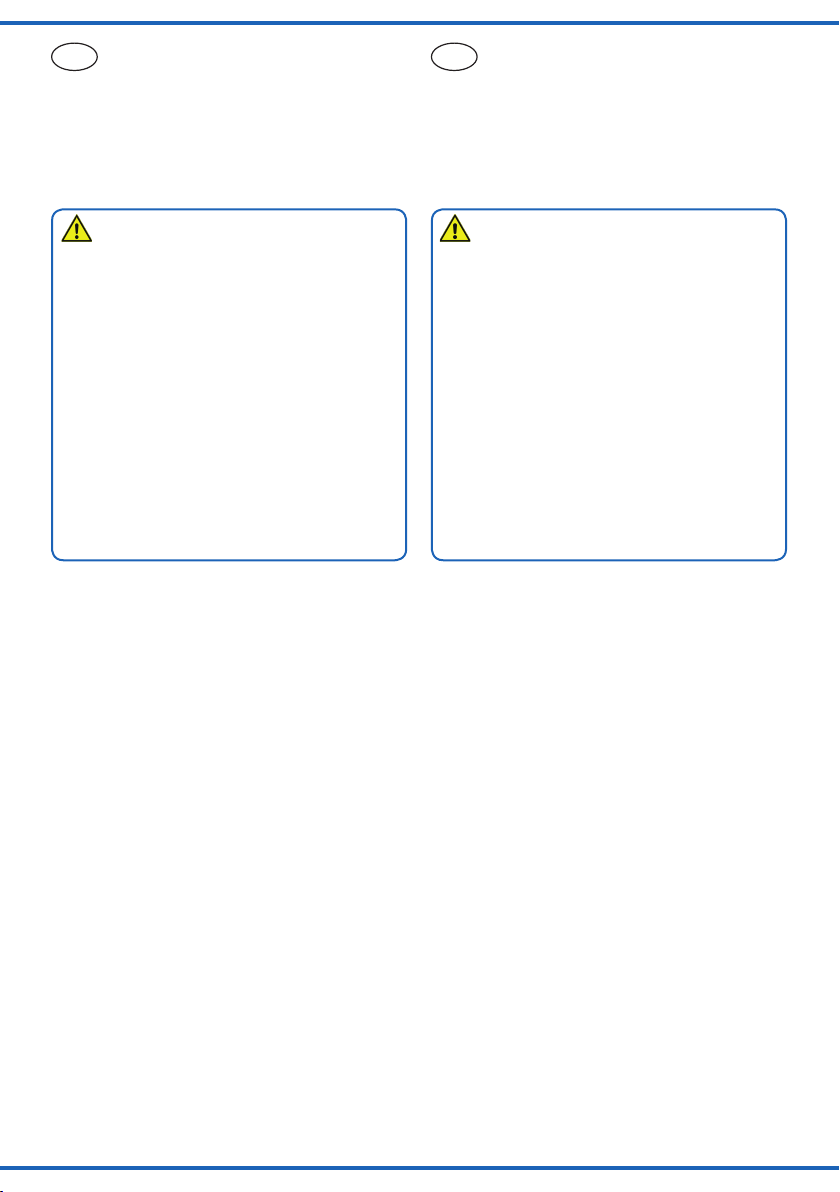
1. Bohren Sie an der Montagestelle ein Loch mit einem
Durchmesser von 4 mm (Abb. 1).
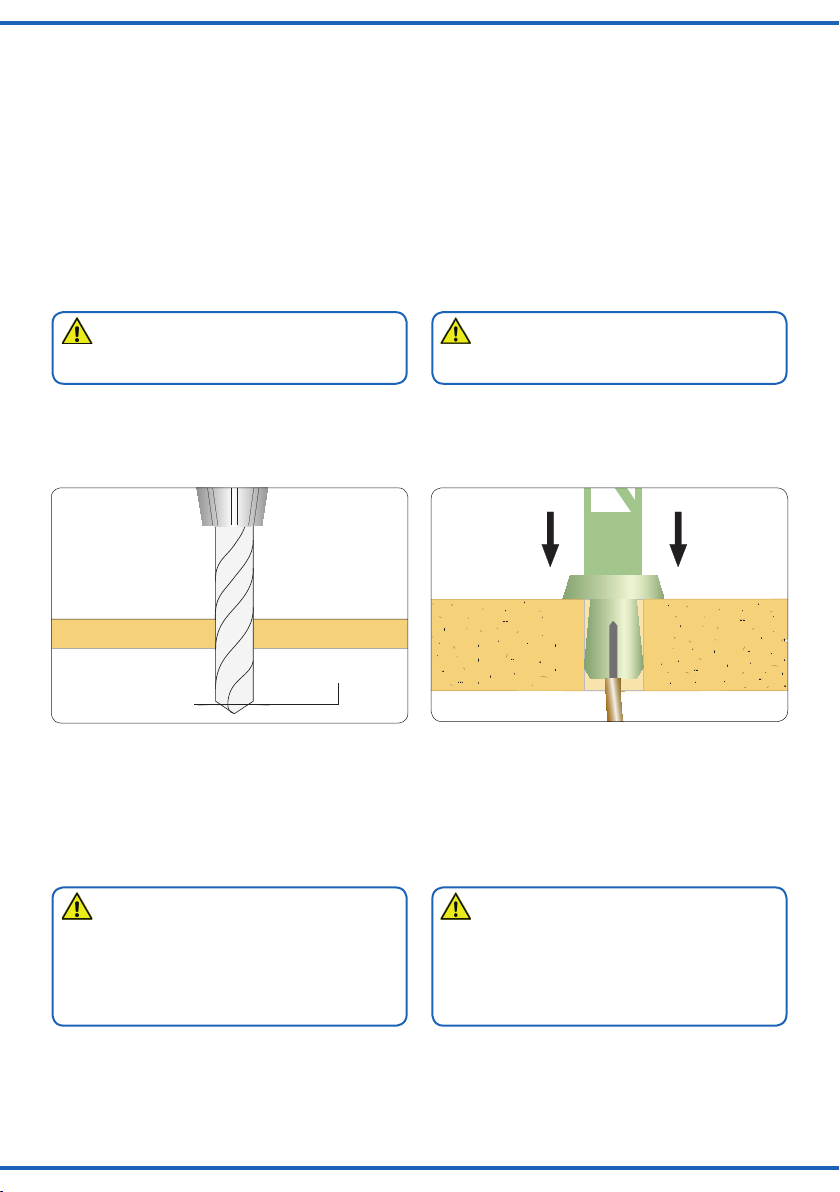
2. Stecken Sie zuerst den Steckfuß mit den Anschluss-
kabeln durch die Bohrung (Abb. 2).
Abb. 1 Abb. 2
Fig. 1 Fig. 2
3. Mounting/Installation
Please note:
Item contains breakable parts. When inserting, touch the
traffic light only at the lower part of the mast.
Mount the traffic lights as described below:
1. Drill a 4 mm hole at the appropriate position on your
layout (see fig. 1).
2. First insert the base with the wire leads into the hole
(see fig. 2).
Ø 4 mm
3. Stecken Sie den Mast der Ampel in den Steckfuß, wo-
durch dieser in der Bohrung festklemmt. Falls der Steckfuß
nicht genügend Halt findet, schieben Sie den Haltering von
unten auf den Steckfuß.
4. Lassen Sie beim Anschließen der Kabel unterhalb der
Ampel eine Schleife von ca. 2 – 3 cm Länge, damit Sie die
Ampel bei eventuellen Arbeiten aus der Montagebohrung
ziehen können.
Achtung!
Wegen der sehr dünnen Drähte zwischen dem Ampelmast und den Verbindungsstellen zu den Anschlusslitzen
darf auf keinen Fall Zug auf die Anschlussleitungen
ausgeübt werden. Das Umbiegen der Drähte muss vorsichtig geschehen und sollte nicht mehrfach erfolgen,
um Drahtbruch zu vermeiden.
Befestigen Sie die elektronische Baugruppe nach Anschluss der Leitungen, z. B. mit einem Klebestreifen, und
sorgen Sie für Zugentlastung der Kabel.
3. Insert the mast of the traffic lights into the base, which
causes the latter to be firmly fastened inside the hole. In
case the base does not sit firmly in the hole, slide the retaining ring onto the base from below.
4. Make sure to leave a short loop (about 2 – 3 cm) below
the base to enable you to remove the mast from the base
and put is sideways on the layout, should this become
necessary for maintenance reasons.
Attention:
Do not exert any undue force to the very thin wires from
the mast to the connecting points of the wiring leads.
Carefully bend the wires preferably only once in order
to avoid any broken wires.
Fasten the electronics after connecting the cables and
make sure there is adequate strain relief for the cables.
3
Page 4

4. Anschluss
Vorsicht:
Widerstände an den Enden der Anschlussdrähte sind für
die Funktion erforderlich. Keinesfalls entfernen! Widerstände nicht mit Isolationsmaterial umhüllen, da sonst
keine ausreichende Kühlung möglich ist!
Beim Betrieb mit Wechselstrom verbinden Sie das blaue
Steuerkabel mit dem braunen Zuleitungskabel. Schließen
Sie beide Kabel sowie das gelbe Zuleitungskabel wie in
Abb. 3 gezeigt an einen Transformator an, z. B. Viessmann
Art. 5200. Im Gleichstrombetrieb verbinden Sie das braune
Kabel und das blaue Steuerkabel mit dem Plus-Pol, das
gelbe Kabel mit dem Minus-Pol.
4. Connection
Caution:
Resistors at the cables are needed for proper function
of the lamp. Never cut them off! Never cover resistor or
diode with insulation material, because they have to be
cooled by surrounding air!
For AC operation connect the blue control cable with the
brown cable. Connect both cables as well as the yellow
lead to a transformer (e. g. Viessmann item 5200) as
shown in fig. 3. For DC operation connect the brown wire
and the blue control wire with the positive („plus“) terminal
and the yellow wire with the negative terminal.
5. Betrieb
Es sind mehrere Betriebsarten möglich: Automatischer
Betrieb als Fußgängerampel im Tagbetrieb, automatischer
Nachtbetrieb und manueller bzw. extern gesteuerter Betrieb.
5.1 Automatischer Betrieb als
Fußgängerampel im Tagbetrieb
Schließen Sie die Ampel gemäß der farbigen Markierungen an die Steuerelektronik an. Schalten Sie dann die
Betriebsspannung ein. Die Steuerung befindet sich nun
im Automatikmodus.
In dieser Betriebsart wechselt die Ampelsteuerung automatisch zwischen den Zuständen „rot“ und „grün“ für die
Fahrzeuge – mit allen erforderlichen Übergängen (Abb.
4). Die Grünphase dauert ca. 30 Sekunden, die Rotphase
ca. 12 Sekunden.
Abb. 3 Fig. 3
5. Operation
There are several operating modes: Automatic operation
as pedestrian traffic light in day-time mode, automatic
night-time mode as well as manual respectively remote
controlled mode.
5.1 Automatic operation as pedestrian
traffic light in day-time mode
Connect the traffic lights to the electronic control while
observing the colour coding. Then switch on the power.
The controls are now in automatic mode.
In this mode the traffic lights automatically alternate between “red” and “green” for the motorized traffic with all
necessary transitions (see fig. 4). The “green” phase lasts
about 30 seconds and the “red” phase for about 12 seconds.
z. B./e. g.
5095
rot/red
gelb/
yellow
grün/
green
4
z. B./e. g.
5200
gelb/yellow
blau/blue
braun/brown
Page 5

Abb. 4
Fig. 4
1. Stabil
1. stabilized
2. Übergang
2. transition
3. Übergang
3. transition
5.2 Automatischer Nachtbetrieb
Verbinden Sie das blaue Steuerkabel mit dem braunen
Zuleitungskabel und stellen Sie mit dem beiliegenden
Widerstand die Brücke an der Steuerelektronik gemäß
Abb. 5 her. Schalten Sie dann die Betriebsspannung ein.
Die Steuerung befindet sich nun im Nachtbetrieb. In dieser
Betriebsart blinkt nur die gelbe Verkehrsampel.
Statt der Brücke kann auch ein Schalter oder ein potentialfreier Kontakt eines Schaltdecoders verwendet werden
(z. B. Art. 5285).
4. Stabil
4. stabilized
5. Übergang
5. transition
6. Übergang
6. transition
5.2 Automatic night-time mode
Connect the blue control wire with the brown cable and
install the bridge on the printed circuit board with the supplied resistor as per fig. 5. Then switch on the power.
The controls are now in automatic night-time mode. In this
mode only the amber lights are blinking.
You may install a switch or galvanically insulated contact
of an accessory decoder instead of the resistor bridge
(e. g. item 5285).
Abb. 5
Fig. 5
Brücke für Nachtbetrieb
wiring bridge for night-time operation
5
Page 6

5.3 Automatischer Betrieb
Zeitrelais
Viessmann
5207
Start
↓
Verzögerung
AusEin
0 3
Minuten
0 3
Minuten
bnge 16 V~
mit manueller Zeiteinstellung
Verbinden Sie die Steuerung der Ampel wie in Abb. 6 mit
einem Zeitrelais (z. B. Viessmann Art. 5207). Über die
Einschaltverzögerung (linkes Poti) stellen Sie die Dauer
der Rotphase ein. Über die Ausschaltverzögerung (rechtes
Poti) steuern Sie die Dauer der Grünphase.
5.4 Manueller Betrieb
Diese Betriebsart ermöglicht die Simulation, dass Fußgänger an der Ampel den Schalter betätigen, wenn sie
die Straße überqueren möchten. Verbinden Sie das blaue
Steuerkabel mit einem Taster (z. B. Viessmann Art. 5547,
Abb. 7) und schalten Sie die Betriebsspannung ein. Die
Steuerung befindet sich nun im ersten stabilen Zustand
aus Abb. 4: Die Fahrzeugampel leuchtet grün, die Fußgängerampel rot. In dieser Betriebsart wird mit dem Taster der
Zustandswechsel ausgelöst. Dabei werden alle Zwischenzustände, die in Abb. 4 mit „Übergang“ gekennzeichnet
sind, automatisch ausgeführt. Die Steuerung wechselt also
aufgrund der Impulse zwischen den beiden als „stabil“ gekennzeichneten Zuständen.
Kurzer Impuls (kürzer als 3 Sekunden):
Die Steuerung wechselt bei kurzem Anlegen der Span
nung an den Steuereingang von einem stabilen Zustand
in den anderen. Alle Übergänge werden dabei ausgeführt.
Die Steuerung bleibt bis zum nächsten Impuls im stabilen
Zustand. So können Sie Abläufe auf Ihrer Anlage mit der
Ampel manuell synchronisieren.
Langer Impuls (länger als 5 Sekunden):
In Verbindung mit einem Zeitrelais (z. B. Viessmann Art.
5207) können Sie die Dauer des Impulses verlängern (Abb.
8). Mit Hilfe des linken Potentiometers steuern Sie die Fahr-
zeugampel: Am Anfang des Impulses wechselt sie auf Rot,
am Ende des Impulses wieder auf Grün. Die Rotphase
wird also mit der Einschaltdauer des Relais gesteuert, die
Grünphase durch die Zeit bis zum nächsten Impuls.
5.3. Automatic operation with manual
timing
Connect the electronic control as shown in fig. 6 with a
time relay (e. g. Viessmann item 5207). Adjust the duration of the “red” phase with the potentiometer on the left.
Via the potentiometer for adjusting the switch-off delay you
can control the duration of the “green” phase.
5.4 Manual operation
This operating mode facilitates the simulation of a pedestrian activating the push button of the traffic light when he
or she wishes to cross the road. Connect the blue wire
with a push button panel (e. g. Viessmann item 5547;
fig. 7) and switch on the power supply. The controls are
now in the first stabilized status as shown in fig. 4: The
traffic light for the motorists displays green and the one
for the pedestrians shows red. The change of the lights
is achieved by pressing the push button. All transitional
phases described as “transition” in fig. 4 are automatically
activated in the proper sequence. Thus the control system
changes between the two states marked as “stable” due to
the pulses generated by the button.
Short pulse (less than 3 seconds):
-
The system changes from one stable status into the one
whenever voltage is applied briefly. All transitional states
will be activated. The system then remains in the latest
stable stage until another pulse is applied. Thus you can
manually synchronize the traffic lights on your layout.
Long pulse (more than 5 seconds):
You may extend the duration of the pulse with the aid
of a time relay (e. g. Viessmann item 5207) as shown
in fig. 8. The left potentiometer allows you to control the
traffic lights for the motorists: At the beginning of a pulse
this traffic light changes to red and returns to green at the
end of the pulse. Thus the red phase is controlled by the
time the relay is switched on while the green phase is controlled by the time until the next pulse is triggered.
6
Abb. 6
z. B./e. g.
5200
gelb/
yellow
grün /
green
rot/
red
blau/blue
gelb/yellow
braun/brown
z. B./e. g.
5207
braun/brown
Fig. 6
Page 7

16 V
10 V
0 V
Universal Tasten - Stellpult
5547
Viessmann
Sekundär
0-10-16 V~
16 V
Primär
230 V~
Gefertigt nach
Lichttransformator
5200
Nur für trockene Räume
Primär 230 V 50 - 60 Hz
Sekundär max. 3,25 A52 VA
ta 25°CIP 40
10 V
0 V
Zeitrelais
Viessmann
5207
Start
↓
Verzögerung
AusEin
0 3
Minuten
0 3
Minuten
bnge 16 V~
Universal Tasten - Stellpult
5547
Viessmann
Hinweis:
Für eine Kreuzung (2 Straßen) benötigen Sie zweimal
Art. 5094/5095 und einmal Art. 5096 Fußgängerampel, 4
Stück. Weitere Details zum Anschluss entnehmen Sie der
Bedienungsanleitung zu Art. 5096.
Hint:
For a crossroad (2 streets) you need two pieces of item
5094/5095 and one of item 5096 pedestrian signal, 4
pieces. Further information regarding the connection you
will find in the operation manual for item 5096.
Abb. 7
z. B./e. g.
5200
gelb/
yellow
gelb/yellow
braun/brown
grün/
green
rot/
red
z. B./e. g.
5095
Fig. 7
blau/
blue
z. B./e. g.
5547
Abb. 8
z. B./e. g.
5200
z. B./e. g.
Fig. 8
5095
gelb/
yellow
rot/
red
z. B./e. g.
5207
braun/brown
z. B./e. g.
5547
grün/
green
blau/blue
gelb/yellow
braun/brown
7
Page 8

Viessmann
hnik GmbH
www.viessmann-modell.de
6. Fehlersuche und Abhilfe
Problem Mögliche Ursache
Ampel funktioniert nicht Steuerkabel nicht
angeschlossen?
Polung bei DC-Betrieb falsch?
Abläufe falsch Anschlüsse der Ampel
falsch gesteckt?
6. Trouble-shooting
Problem Possible cause
Traffic light does Missing connection of the
not work
Wrong polarity in DC mode?
Wrong sequences Connections to the traffic lights
inadvertently inserted in the
wrong way?
control wire?
7. Gewährleistung
Jeder Artikel wurde vor Auslieferung auf volle Funktionalität
geprüft. Der Gewährleistungszeitraum beträgt 2 Jahre ab
Kaufdatum. Tritt in dieser Zeit ein Fehler auf und Sie finden
die Fehlerursache nicht, nehmen Sie bitte Kontakt mit uns
auf (service@viessmann-modell.com).Senden Sie uns
den Artikel zur Kontrolle bzw. Reparatur bitte erst nach
Rücksprache zu. Wird nach Überprüfung des Artikels ein
Herstell- oder Materialfehler festgestellt, wird er kostenlos
instandgesetzt oder ausgetauscht. Von der Gewährleistung
und Haftung ausgeschlossen sind Beschädigungen des
Artikels sowie Folgeschäden, die durch unsachgemäße
Behandlung, Nichtbeachten der Bedienungsanleitung, nicht
bestimmungsgemäßen Gebrauch, eigenmächtigen Eingriff,
bauliche Veränderungen, Gewalteinwirkung, Überhitzung
u. ä. verursacht werden.
8. Technische Daten
Betriebsspannung: 10 – 16 V AC ~
Höhe: 41 mm
Entsorgen Sie dieses Produkt nicht über den
(unsortierten) Hausmüll, sondern führen Sie
es der Wiederverwertung zu.
Änderungen vorbehalten. Keine Haftung für Druckfehler
und Irrtümer.
Die aktuelle Version der Anleitung finden Sie auf der Viessmann Homepage unter der Artikelnummer.
Modellbauartikel, kein Spielzeug! Nicht geeignet für Kinder
DE
unter 14 Jahren! Anleitung aufbewahren!
Model building item, not a toy! Not suitable for children
EN
under the age of 14 years! Keep these instructions!
Ce n’est pas un jouet. Ne convient pas aux enfants de
FR
moins de 14 ans ! C’est un produit décor! Conservez cette
notice d’instructions!
Não é um brinquedo!Não aconselhável para menores de
PT
14 anos. Conservar o manual de instruções.
14 – 24 V DC =
7. Warranty
Each model is tested as to its full functionality prior to delivery. The warranty period is 2 years starting on the date
of purchase. Should a fault occur during this period please
contact our service department (service@viessmannmodell.com). Please send the item to the Viessmann service department for check and repair only after consultation. If we find a material or production fault to be the cause
of the failure the item will be repaired free of charge or
replaced. Expressively excluded from any warranty claims
and liability are damages of the item and consequential
damages due to inappropriate handling, disregarding the
instructions of this manual, inappropriate use of the model,
unauthorized disassembling, construction modifications
and use of force, overheating and similar.
8. Technical data
Operating voltage: 10 – 16 V AC ~
14 – 24 V DC =
Height: 41 mm
Do not dispose of this product through (unsorted)
domestic waste, supply it to recycling instead.
Subject to change without prior notice. No liability for
mistakes and printing errors.
You will find the latest version of the manual on the Viessmann website using the item number.
Modelbouwartikel, geen speelgoed! Niet geschikt voor
NL
kinderen onder 14 jaar! Gebruiksaanwijzing bewaren!
Articolo di modellismo, non è un giocattolo! Non adatto
IT
a bambini al di sotto dei 14 anni! Conservare istruzioni per
l’uso!
Artículo para modelismo ¡No es un juguete! No
ES
recomendado para menores de 14 años! Conserva las
instrucciones de servicio!
Modelltec
Bahnhofstraße 2a
D - 35116 Hatzfeld-Reddighausen
info@viessmann-modell.com
8
Made in Europe
85562
Stand 05/fa
01/2020
Ho/Kf
 Loading...