

Page 1
Bedienungsanleitung
Innovation,
Operation Manual
5061
5062 modern
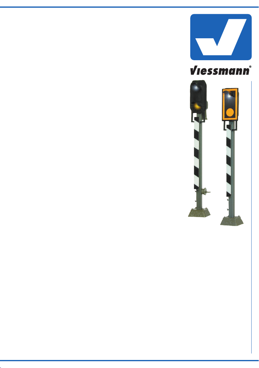
H0 BlinklichtÜberwachungssignal
H0 Route indicator blinking
signal
5061
5062
1. Wichtige Hinweise / Important information ........................................................ 2
2. Einleitung / Introduction ..................................................................................... 2
3. Funktionskontrolle / Functional test ................................................................... 3
4. Einbau / Mounting ............................................................................................. 3
5. Anschluss / Connection ..................................................................................... 3
6. Technische Daten / Technical data .................................................................... 4
die bewegt!
Page 2
DE
EN
1. Wichtige Hinweise
Bitte lesen Sie vor der ersten Anwendung des Produktes
bzw. dessen Einbau diese Bedienungsanleitung aufmerksam durch. Bewahren Sie diese auf, sie ist Teil des Produktes.
1.1 Sicherheitshinweise
Vorsicht:
Verletzungsgefahr!
Aufgrund der detaillierten Abbildung des Originals bzw.
der vorgesehenen Verwendung kann das Produkt Spitzen, Kanten und abbruchgefährdete Teile aufweisen. Für
die Montage sind Werkzeuge nötig.
Stromschlaggefahr!
Die Anschlussdrähte niemals in eine Steckdose einführen! Verwendetes Versorgungsgerät (Transformator,
Netzteil) regelmäßig auf Schäden überprüfen. Bei Schäden am Versorgungsgerät dieses keinesfalls benutzen!
Alle Anschluss- und Montagearbeiten nur bei abgeschal
teter Betriebsspannung durchführen!
Ausschließlich nach VDE/EN gefertigte Modellbahntransformatoren verwenden!
Stromquellen unbedingt so absichern, dass es bei einem
Kurzschluss nicht zum Kabelbrand kommen kann.
1.2 Das Produkt richtig verwenden
Dieses Produkt ist bestimmt:
- Zum Einbau in Modelleisenbahnanlagen und Dioramen.
- Zum Anschluss an eine geeignete Blinkelektronik (z. B.
5065).
- Zum Betrieb in trockenen Räumen.
Jeder darüber hinausgehende Gebrauch gilt als nicht be-
stimmungsgemäß. Für daraus resultierende Schäden haftet
der Hersteller nicht.
-
1. Important information
Please read this manual completely and attentively before
using the product for the first time. Keep this manual. It is
part of the product.
1.1 Safety instructions
Caution:
Risk of injury!
Due to the detailed reproduction of the original and the
intended use, this product can have peaks, edges and
breakable parts. Tools are required for installation.
Electrical hazard!
Never put the connecting wires into a power socket!
Regularly examine the transformer for damage. In case
of any damage, do not use the transformer.
Make sure that the power supply is switched off when
you mount the device and connect the cables!
Only use VDE/EN tested special model train transformers for the power supply!
The power sources must be protected to avoid the risk
of burning cables.
1.2 Using the product for its correct purpose
This product is intended:
- For installation in model train layouts and dioramas.
- For connection to blinker electronics (e. g. 5065).
- For operation in dry rooms only.
Using the product for any other purpose is not approved
and is considered inappropriate. The manufacturer is not
responsible for any damage resulting from the improper
use of this product.
1.3 Packungsinhalt überprüfen
Kontrollieren Sie den Lieferumfang auf Vollständigkeit:
- Signal mit Anschlusskabeln
- Haltering
- Anleitung
2. Einleitung
2.1 Vorbild / Aufstellung
Das Blinklicht-Überwachungssignal wird beim Vorbild zur
Überwachung von Bahnübergängen mit Blinklicht (mit
und ohne Halbschranken) verwendet, wenn dieser Bahnübergang durch den fahrenden Zug eingeschaltet wird.
Dabei zeigt das obere Blinklicht dem Lokführer an, dass
die eingeschaltete Bahnübergangssicherung einwandfrei
funktioniert. Blinkt das obere Licht nicht, muss der Zug vor
dem Übergang halten und dieser erst durch das Zugpersonal gesichert werden, bevor der Zug weiterfahren darf.
2
1.3 Checking the package contents
Check the contents of the package for completeness:
- Signal with connection cables
- Retaining ring
- Manual
2. Introduction
2.1 Prototype / Set-up
The route indicator blinking signal is used for monitoring
level crossings with indicators (with and without half level
crossing barriers) if it is switched on by the train. The upper blinking light shows the engine driver that the level
crossing barrier is working. If the light is not blinking, the
train has to stop in front of the level crossing. After the
train personnel has secured the level crossing, the train is
allowed to drive on.
Page 3

Das untere gelbe Licht ist als Kennlicht des Signals immer
eingeschaltet. Bei der modernen Version (Art. 5062), die
seit 1986 eingesetzt wird, ist dieses gelbe Licht durch einen gelben Aufdruck ersetzt worden. Das Signal steht im
Bremswegabstand vor dem eigentlichen Bahnübergang.
Es wird bei Nebenbahnen mit Geschwindigkeiten bis 100
km/h verwendet.
The lower yellow light is always on. For the modern version (item 5062), which is used since 1986, the yellow
light has been replaced by a yellow imprint. The indicator
observation signal is placed in braking distance in front of
the level crossing. It is used on branch lines with maximum
speeds of 100 km/h.
2.2 Modell
Das Viessmann Blinklicht-Überwachungssignal gewährleistet einen vorbildgerechten Einsatz auf der Modellbahn, da
alle Funktionen vorhanden sind. Hierzu ist das Signal mit
einer ständig leuchtenden gelben LED als Kennlicht (Art.
5061) bzw. einem gelben Aufdruck (Art. 5062) im unteren
Teil des Mastschirmes ausgestattet. Im oberen Teil befindet
sich eine weiße LED, die über die Blinkelektronik Art. 5065
des zu überwachenden Bahnüberganges (Andreaskreuze)
angeschlossen wird.
Ein vorbildgerechter Abstand zwischen Signal und Bahnübergang beträgt etwa zwei Loklängen.
Viele weitere Informationen über Signale finden Sie im
Viessmann-Signalbuch (Art. 5299).
3. Funktionskontrolle
Prüfen Sie vor dem Einbau des Signals die Funktion, indem Sie das Blinklicht-Überwachungssignal probeweise
entsprechend Abb. 2 an der Blinkelektronik Art. 5065 anschließen.
4. Einbau
1. Bohren Sie an der Montagestelle ein Loch mit 5,5 mm
Durchmesser (Abb. 1).
2. Führen Sie die Anschlusskabel mit dem Stecker von
oben durch das Montageloch und stecken Sie dann das
Signal mit dem Patentsteckfuß hinein.
Abb. 1
2.2 Model
The Viessmann route indicator blinking signal can show
all aspects, which ensures a realistic use on your layout.
For that the signal is equipped with a permanently burning
yellow LED as identity light (item 5061) or a yellow imprint
(item 5062) on the lower side of the signal head. On the
upper side of the signal there is a white LED, which can
be connected to the blinker electronics item 5065 of the
level crossing.
So you can choose a distance from the signal to the level
crossing of two locomotive lengths.
More information about signals you will find in the Viessmann signal book (item 5299, German version only).
3. Functional test
Please test the function of the signal before mounting by
connecting the route indicator blinking signal to the blinking electronics item 5065 as is shown in fig. 2.
4. Mounting
1. Drill a hole with 5.5 mm diameter at the mounting place
(fig. 1).
2. The signal‘s connection wire with the plug has to be
inserted into the hole first. After that put the signal with
the patented base socket into that hole.
Fig. 1
5,5 mm
5. Anschluss
Vorsicht!
Entfernen Sie keinesfalls die Widerstände sowie die
Diode (Art. 5061).
Schließen Sie das Blinklicht-Überwachungssignal gemäß
Abb. 2 an.
5. Connection
Caution!
Never cut off the resistors or the diode (item 5061).
Connect the route indicator blinking signal as shown in
fig. 2.
3
Page 4

Viessmann
hnik GmbH
www.viessmann-modell.de
Abb. 2
/ yellow
Lichttransformator
Primär
230 V~
Primär 230 V 50 - 60 Hz
Sekundär max. 3,25 A52 VA
Nur für trockene Räume
10 V
Sekundär
0-10-16 V~
ta 25°CIP 40
0 V
Gefertigt nach
VDE 0570
EN 61558
16 V
5200
z. B. / e. g. 5200
schwarz
Diode
black
gelb
gelb
yellow
braun
brown
Anschluss s. 5065
connect. see 5065
viessmann
4-fach-Blinkgerät 5065
1
schwarz
black
16 V ~bn
ge
ge
4
32
5061 5062
/ white / white
weiß weiß
zu den Andreaskreuzen
to the St. Andrews crosses
Fig. 2
6. Technische Daten
Anschluss: an Blinkelektronik Art. 5065!
Stromversorgung: 10 – 16 V AC ~
(mit und ohne 5215 Powermodul)
14 – 24 V DC =
13 – 24 V Digitalsignal
Höhe: 56 mm
Entsorgen Sie dieses Produkt nicht über den
(unsortierten) Hausmüll, sondern führen Sie es
der Wiederverwertung zu.
Änderungen vorbehalten. Keine Haftung für Druckfehler
und Irrtümer.
Die aktuelle Version der Anleitung finden Sie auf der Viessmann Homepage unter der Artikelnummer.
Modellbauartikel, kein Spielzeug! Nicht geeignet für Kinder
DE
unter 14 Jahren! Anleitung aufbewahren!
Model building item, not a toy! Not suitable for children
EN
under the age of 14 years! Keep these instructions!
Ce n’est pas un jouet. Ne convient pas aux enfants de
FR
moins de 14 ans ! C’est un produit décor! Conservez cette
notice d’instructions!
Não é um brinquedo!Não aconselhável para menores de
PT
14 anos. Conservar o manual de instruções.
Modelltec
Bahnhofstraße 2a
D - 35116 Hatzfeld-Reddighausen
info@viessmann-modell.com
4
6. Technical data
Connection: to blinking electronics item 5065!
Power Supply: 10 – 16 V AC ~
(with and without item 5215 power modul)
14 – 24 V DC =
13 – 24 V digital signal
Height: 56 mm
Do not dispose of this product through (unsorted)
domestic waste, supply it to recycling instead.
Subject to change without prior notice. No liability for
mistakes and printing errors.
You will find the latest version of the manual on the Viessmann website using the item number.
Modelbouwartikel, geen speelgoed! Niet geschikt voor
NL
kinderen onder 14 jaar! Gebruiksaanwijzing bewaren!
Articolo di modellismo, non è un giocattolo! Non adatto
IT
a bambini al di sotto dei 14 anni! Conservare istruzioni per
l’uso!
Artículo para modelismo ¡No es un juguete! No
ES
recomendado para menores de 14 años! Conserva las
instrucciones de servicio!
98796
Stand 06/sw
Made in Europe
06/2020
Ho/Kf
 Loading...