

Page 1
Bedienungsanleitung
AC
~
DC
=
DCC
LED
K
Operation Manual
Digital Funktionsmodell mit
Bewegung
Digital Functional Model
with movement
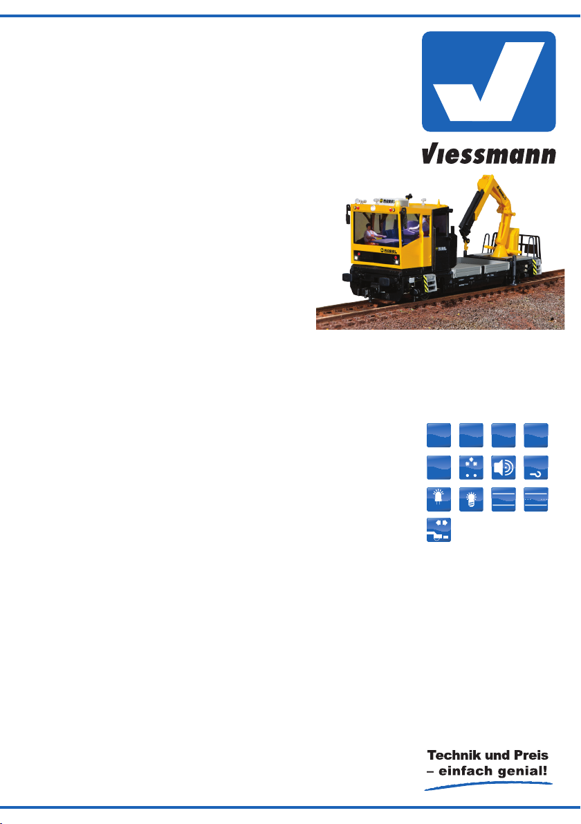
26110 - H0 ROBEL Gleiskraftwagen 54.22,
Funktionsmodell für Zweileitersysteme
26110 - H0 ROBEL Track Motor Car
Functional model - 2 rail version
26111 - H0 ROBEL Gleiskraftwagen 54.22,
Funktionsmodell für Dreileitersysteme
26111 - H0 ROBEL Track Motor Car
functional model - 3 rail version
1. Wichtige Hinweise ........................... 2
2. Transport und Verpackung .............. 3
3. Einführung / Eigenschaften ............. 5
4. Betrieb ............................................. 5
5. Konguration des Decoders ............ 11
6. Wartung ........................................... 16
7. Vorbild .............................................. 19
8. Fehlersuche & Abhilfe ...................... 20
9. Ersatzteile ........................................ 21
10. Technische Daten ............................ 24
1. Important Information ...................... 2
2. Transport and packaging ................. 3
3. Introduction / characteristics ............ 5
4. Operation ......................................... 5
5. Conguration of the decoder ........... 11
6. Maintenance .................................... 16
7. Prototype ......................................... 19
8. Troubleshooting ............................... 20
9. Spare parts ...................................... 21
10. Technical Data ................................. 24
Rail
Com
MM
◄►
NEM
2L 3L
Page 2
DE EN
1. Wichtige Hinweise
Lesen und beachten Sie vor Gebrauch die Sicherheitshinweise und diese Anleitung und bewahren Sie sie auf. Sie ist Teil des Produktes.
1. Important Information
Read and follow these safety precautions and instructions carefully before use! Keep this manual.
It is part of the product.
Sicherer Betrieb
Vorsicht: Verletzungsgefahr! Aufgrund
der detaillierten Nachbildung des Originals
bzw. der vorgesehenen Verwendung kann
das Produkt Spitzen, Kanten und abbruch-
gefährdete Teile aufweisen. Das Produkt
gehört aus diesem Grund nicht in die Hände von Kindern!
Vorsicht: Stromschlaggefahr! Verwendetes Versorgungsgerät (Transformator,
Netzteil) regelmäßig auf Schäden an Kabeln, Stecker, Gehäuse usw. prüfen. Bei
Schäden am Versorgungsgerät dieses keinesfalls benutzen!
Achtung: Das Modell enthält eine elektro-
nische bzw. mechanische Baugruppe. Es
ist nicht vorgesehen, dass das Modell vom
Kunden geöffnet wird. Es darf nicht beschädigt oder Feuchtigkeit ausgesetzt wer-
den. Die genannten Baugruppen sind für
den einwandfreien Betrieb erforderlich.
Achtung: Bruchgefahr! Modell stets vorsichtig am Gehäuse anfassen, da die ligranen Teile des Modells sonst abbrechen
könnten.
Achtung: Betreiben Sie den Robel Gleis-
kraftwagen niemals unbeaufsichtigt und
verwenden Sie ihn niemals zur Beförderung von Personen oder Tieren.
Das Produkt richtig verwenden
Das Produkt darf ausschließlich dieser Anleitung gemäß verwendet werden. Dieses Schie-
nenfahrzeugmodell ist bestimmt
• zum Betrieb auf Modelleisenbahnanlagen
der Baugröße H0,
• zum Betrieb mit einem zugelassenen
Modellbahntransformator mit einer Ausgangsspannung von max. 21 V bzw. an
einer Digitalzentrale der Formate DCC
und / oder Märklin Motorola (MM) wie
bspw. dem Viessmann Commander 5300,
• zum Betrieb in trockenen Räumen.
Jeder darüber hinausgehende Gebrauch gilt als
nicht bestimmungsgemäß. Der Hersteller haftet
nicht für daraus resultierende Schäden. Dies ist
ein Sammlermodell! Nicht geeignet für Kinder unter 14 Jahren. Bei unsachgemäßem Gebrauch be-
2
Safe operation
Attention: Risk of injury! Due to the detailed reproduction of the prototype respectively the intended application this product
may have sharp edges and parts prone to
breaking. Therefore this product is not intended for children!
Take care: Risk of electrocution! Please
check the power supply (transformer, power supply unit) regularly for damaged cables, plugs etc. or damage to the housing.
Should there be any damage do not use
this power supply anymore!
Attention: The model contains electronic
respectively mechanical subassemblies. It
should not be opened by the client. It may
not be damaged or exposed to humidity.
The subassemblies mentioned above are
essential for trouble-free operation.
Attention: Risk of breakage! Always handle this model carefully since the many
nely detailed parts may otherwise be damaged.
Attention: Never leave the Robel track
motor car unattended during operation and
never use it for transporting persons or
animals.
Using this product for its correct
purpose
This product may only be used as described in
this manual. This rail-bound vehicle is intended
for operation as follows
• For operation on a H0 model train layout,
• For operation with an approved transformer for model trains with a secondary voltage of max 21 V respectively a digital
command station supplying DCC and / or
Märklin Motorola (MM) such as the Viess-
mann Commander 5300,
• For operation in dry rooms.
Any other use of this product is not permitted. The
manufacturer is not liable for any damage due to
inappropriate use. This is a collector´s item! Not
suitable for children less than 14 years old. Inappropriate use may result in injury.
Page 3
steht Verletzungsgefahr.
2. Transport und Verpackung
Der Robel Gleiskraftwagen ist ein fein detailliertes
und empndliches Modell. Damit Sie lange Freu-
de an diesem Fahrzeug haben, ist er gut verpackt
und verschiedene Zurüstteile sind im Auslieferungszustand nicht montiert. Wir empfehlen, den
Robel Gleiskraftwagen bei Nichtgebrauch in der
Originalverpackung zu lagern.
Lieferumfang
Kontrollieren Sie nach dem Auspacken den Lieferumfang auf Vollständigkeit:
► Modell Robel Gleiskraftwagen,
► Beutel mit Zurüst- und Ersatzteilen,
► diese Anleitung.
Fahrzeug aus der Transportverpackung
entnehmen
Bitte alle Verpackungsteile und diese Anleitung
für späteren Gebrauch aufbewahren. Nur die Originalverpackung garantiert Schutz vor Transportschäden. Zur besseren Entnahme des Fahrzeugs
aus dem Styroporträger ist diese in etwa in der
Mitte der Pritsche mit einer Vertiefung ausgestattet, die das sichere Entnehmen des Modells er-
laubt.
Achtung: Bruchgefahr! Modell stets vor-
sichtig in der Eingreifvertiefung der Verpa-
ckung an der Pritsche anfassen, da die ligranen Teile des Modells sonst abbrechen
könnten. Niemals am Dach oder Kranauf-
bau festhalten.
► Styroporträger seitlich aus dem Karton
nehmen.
► Das Fahrzeug vorsichtig in der Eingreifvertie-
fung der Verpackung an der Pritsche anfassen
und das Fahrzeug gleichmäßig aus dem Styroporträger ziehen. Gegebenenfalls Styroporträ-
ger xieren.
► Fahrzeug aufrecht auf einen Tisch oder auf die
Gleise stellen.
► Alle Teile der Verpackung für späteren Ge-
brauch aufheben.
Fahrzeug in Transportverpackung
verpacken
Achtung: Zerstörungsrisiko! Der Kranaufbau muss sich über der Ladeäche benden, damit das Fahrzeug korrekt in den
Styroporeinleger der Verpackung passt!
Der Kran wird von den zylindrischen Konturen der Verpackung sicher gehalten.
2. Transport and packaging
The Robel track motor car is a nely detailled and
sensitive model. In order to assure that you may
enjoy this product for a long period of time it has
been packed carefully. Some detail parts are not
yet mounted. We recommend to store the vehicle
in its original packaging when not in use.
Purchased parts package
Please check that all parts have been supplied
and that the package is complete:
► Model of Robel track motor car,
► Pouch with detail parts and spare parts,
► This manual.
Removing the vehicle from the transport
packing
Please keep all parts of the packaging and this
manual for later use. Only the original packaging
protects the model from transport damage. In order to make removing the vehicle easier the styrofoam base has an indentation at the centre.
Attention: risk of breakage! Always hold
the model with both hands on the hous-
ing, since some of the ne detail parts
may break. Never hold it by the aggregate
frame, the roof or the bogies.
.
► Remove Styrofoam base sideways
from the carton.
► Carefully grab the vehicle at the indetation in
the packaging and pull it evenly from the styrofoam base.
► Place the vehicle upright on a table or onto the
track.
► Keep all parts of the packaging for later use.
Inserting the vehicle in the transport
packaging
Attention: Risk of damage or destruction! The crane structure must be locat-
ed above the loading platform before placing the vehicle in the styrofoam base! The
crane is held in place by the cylindrical contour of the packaging.
3
Page 4

3. Einführung / Eigenschaften
Der Robel Gleiskraftwagen ist eine hochwertige
Arbeitsmaschine, die wegen der hohen Zugkraft
durch die besondere Antriebstechnik auch bestens für den Übergabeverkehr geeignet ist.
Dieses Modell überzeugt mit einer neuartigen, einzig hierfür entwickelten, Antriebstechnologie, die
der achen Bauweise dieses Gleisbaufahrzeuges
angepasst ist und trotzdem mit sehr stabilen Fahreigenschaften überzeugt. Bei Langsamfahrt, im
Betrieb mit Sound, digital und analog überzeugt
der Robel auf ganzer Linie. Das Fahrzeug ist vielseitig einsetzbar und gehört auf jede Modellbahnanlage. Mit elektrischem Antrieb, fahrtrichtungsabhängiger Dreilicht-Spitzenbeleuchtung bzw.
roten Schlussleuchten, gelber Warnblinkleuchte
und beleuchteter Fahrerkabine. Mit integriertem
Soundmodul für verschiedene Betriebsgeräusche.
RailCom-fähiger Digitaldecoder für DCC / MM und
Analogbetrieb.
Ein integrierter Stromspeicher ermöglicht eine
ausgezeichnete Langsamfahrt auch über Weichen
oder verschmutzte Stellen. Um die Wirkung dieses Stromspeichers besonders effektiv nutzen zu
können, verfügt dieses Modell über eine Besonderheit. Wenn sehr häuge oder längere Strom-
unterbrechungen bei sehr langsamer Fahrt auf-
treten, dann beschleunigt das Modell geringfügig,
um die Strecke mit schlechter Kontaktgabe innerhalb der durch den Stromspeicher verfügbaren
Zeit zu überwinden.
Diese Beschleunigung hilft vielfach, eine Strecke
zu durchfahren, die ohne diese Maßnahme zeit-
lich nicht zu durchfahren wäre.
Ergänzt wird diese Eigenschaft durch einen spe-
ziellen Bremsmodus. Wenn das Modell für eine
einstellbare Zeit keinerlei Gleisspannung erkennt,
dann wird wegbezogen gebremst. Der Bremsweg
ist ebenfalls einstellbar. So können Sie vorgeben,
auf welcher Strecke das Modell zum Stillstand
kommen soll, um z.B. sicher innerhalb stromlos
gemachter Abschnitte anzuhalten oder im Falle
eines Notaus nicht unnötig weit zu fahren.
Bitte beachten Sie, dass im Analog-Betrieb diese
Eigenschaften nur bedingt zur Verfügung stehen,
da der Stromspeicher nicht immer voll geladen
werden kann. Dies gilt um so mehr, je niedriger
die Gleisspannung ist.
4. Betrieb
Der Robel Gleiskraftwagen ist für analogen und
digitalen Betrieb geeignet. Für den vorbildgerechten Einsatz und die Nutzung aller Zusatzfunk-
tionen empfehlen wir die Verwendung eines Digitalsystems. Der integrierte Decoder versteht die
Digitalformate Märklin-Motorola (MM) und DCC.
4
3. Introduction / characteristics
The Robel track motor car is a sophisticated piece
of working equipment, which - due to its considerable pulling power - may well be used for transfer
runs to remote rail customers.
This model convinces the most discerning modeller due to its innovative, specially developed drive
technology perfectly matching the at design of
this track maintenance vehicle while featuring excellent driving characteristics. The Robel offers
outstanding performance under all circumstances
even at low speeds, when operating with sound,
in digital or analogue mode. It is extremely versatile in its potential use and is a must for every
model train layout. It has an electric drive, directional lighting (three white lights and two red lights
at either end), a yellow warning beacon and an illuminated drivers cab. The integral sound module
generates various sounds and the RailCom capable digital decoder is suitable for DCC and MM as
well as analogue mode.
The integral power storage module allows for perfect running at low speeds on turnouts and other spots with poor current pick-up. In order to be
able to utilise this power storage module really effectively this model offers yet another speciality.
If frequent or longer-lasting current interruptions
occur at low speed then the model accelerates
slightly in order to traverse the sector with poor
current pick-up before the power storage module
runs out of energy.
This acceleration often helps to get across spots
that would otherwise cause an unintentional stop
of the vehicle.
In addition, a special braking mode supplements
this feature. If the model does not detect any
track voltage for a pre-determined time, it will slow
down based on a given braking distance. This
braking distance is, of course, adjustable. Thus
you may choose the distance from starting braking until the vehicle comes to a complete standstill. This may be useful for assuring stopping the
vehicle inside stop sectors in front of a signal or in
case of an emergency stop.
Please keep in mind, that on an analogue operated layout the power storage module may not always be fully charged, especially when the loco is
operated at low track-voltages. The functions described above will therefore not be so effective as
under digital operation and are partially not supported.
4. Operation
The Robel track motor car is suitable for both analogue and digital operation. We recommend operating this vehicle in digital mode in order to run it
Page 5
Er erkennt automatisch, mit welchem Digitalformat
er angesprochen wird und stellt sich darauf ein.
Ab Werk eingestellte Adresse: 03 (DCC / MM).
Fahrstufenmodus: DCC 28 Fahrstufen
Tipp: Bei Verwendung einer multiprotokoll-
fähigen Digitalzentrale empfehlen wir den
Betrieb mit dem Protokoll DCC und einer
digitalen Ausgangsspannung von 17 - 21
V. So lassen sich die optimalen Betriebseigenschaften erzielen.
Funktionsumfang
Sämtliche digital schaltbaren Funktionen des Ro-
bel Gleiskraftwagens entnehmen Sie bitte der
Tabelle unten. Der Robel Gleiskraftwagen verfügt über folgende Ausstattung:
► Fahren vorwärts / rückwärts (digital, analog)
► RailCom-fähiger Digitaldecoder für DCC / MM
und Analogbetrieb
► Funktionen digital schaltbar
► Lichtfunktionen: fahrtrichtungsabhängige Drei-
licht-Spitzenbeleuchtung / rote Schlussleuchten, gelbe Warnblinkleuchte sowie Kabinenbeleuchtung
► Soundmodul für verschiedene Betriebsge-
räusche
► Kupplungsschächte nach NEM 362 beidsei-
tig. Im Lieferzustand sind die Kupplungen nicht
montiert.
► Lastregelung für Fahrbetrieb (digital)
► Vorbildkonforme Höchstgeschwindigkeit auch
im Analogbetrieb durch automatische Anpassung an eine zu hohe Trafospannung
► Unterstützung der RailCom-Datagramme Be-
fehlsquittungen, CV-Inhalte, Adressbroadcast
Funktionstastenbelegung
Die Zusatzfunktionen sind den Funktionstasten
gemäß der Tabelle ab Seite 10 zugeordnet:
Tipp: Bei Funktionstasten (z. B. Pfeife und
diverse andere Tasten zur manuellen Betätigung) sollten, sofern die Zentrale dies
unterstützt, die Momenttasten benutzt werden.
Programmierung der Funktionen:
Die Funktionen des Decoders richten Sie über die
CV-Programmierung ein. Sämtliche Einstellmöglichkeiten nden Sie in Kapitel 5.
Digitalbetrieb (DCC / MM)
Im Digitalbetrieb sind alle Funktionen verfügbar
und über Funktionstasten separat steuerbar (vgl.
Abschnitt Funktionstastenbelegung). Im DCC-Be-
like the prototype and to enjoy all special features
this model offers.
The integral decoder supports Märklin-Motorola
(MM) as well as DCC. It automatically detects the
available digital data format.
Default address: 03 (DCC and MM).
Speed step mode: DCC 28 speed steps
Hint: When using a multiprotocol digital
command station we recommend operating
this model with DCC at a digital output voltage ranging between 17 - 21 V. Thus you
will achieve optimal operating properties.
Available functions
All digitally controlled functions of the Robel track
motor car can be found in the table below. The
Robel track motor car is equipped with the following:
► Running forward / reverse (digital, analogue)
► RailCom capable digital decoder for DCC / MM
and analogue operation
► Functions can be separately switched in digital
mode
► Lighting functions: Directional headlights (three
white headlights) / red tail lights, yellow warning
beacon as well as white cab lighting
► Sound module generating various operating
sounds
► Pivoting coupler pockets as per NEM 362 at
both ends. Couplers are not mounted ex works.
► Load compensation in running mode (digital)
► Prototypical maximum speed even in analogue
mode due to automatic adaptation to excessive
supply voltage
► Supporting RailCom datagram command con-
rmations, CV content, address broadcast
Allocation of function buttons
The auxiliary functions are mapped to the following function buttons:
Hint: For certain functions (e.g.: horn and
others for controlling various features of
the tamping unit) you should set the corresponding function buttons to momentary action (provided the command stations
supports this feature).
Programming functions:
You can set all decoder parameters by means of
CV programming or in register mode. You will nd
all available options in chapter 5.
5
Page 6
trieb beherrscht der Decoder die Fahrstufenmodi 14, 28 und 128 Fahrstufen. Die Lastregelung
sorgt für seidenweichen und leisen Fahrbetrieb.
Analogbetrieb
Achtung: Verwenden Sie für den Ana-
logbetrieb ausschließlich regelbare Modelleisenbahntrafos. Der Betrieb mit Ana-
log-Fahrreglern mit Pulsweitensteuerung
(PWM) ist nicht möglich und kann zu Fehlfunktionen führen.
Der Robel Gleiskraftwagen lässt sich auch auf
analog gesteuerten Gleich- und Wechselstrom-
Modellbahn-Anlagen betreiben. Der Funktionsumfang ist jedoch systembedingt eingeschränkt. Die
Funktionen, die im Analogbetrieb aktiv sein sollen,
können eingestellt werden, siehe CV-Tabelle auf
den Seiten 10 - 12.
Ab einer Spannung von ca. 8 V setzt das Mo-
torengeräusch ein. Wenn der Transformator eine
Spannung von etwa 9 V abgibt, fährt die Lok langsam los.
Für den Analogbetrieb eigenen sich sowohl
Gleichstromtrafos (z.B.: von Roco® oder Fleischmann) als auch Wechselstromtrafos (z.B.: von
Märklin®, Titan).
Empfehlung: Drehen Sie den Trafo für kurze
Stopps (Betriebshalte) nicht ganz auf null, sondern lassen Sie eine minimale Spannung zur Ver-
sorgung des Decoders (Beleuchtung etc.) am
Gleis. Dies stellt auch sicher, dass der Stromspeicher geladen ist, wenn das Modell startet.
Digitale Zusatzfunktionen
Dreilicht-Spitzenbeleuchtung / Schlussleuchten: (F0)
Spitzenlicht (weiß) und Schlussleuchten (rot)
sind gekoppelt und nur gemeinsam schaltbar. Sie
wechseln automatisch mit der Fahrtrichtung.
Soundmodul: (F1)
Das integrierte Soundmodul enthält verschiedene betriebsabhängige Geräusche. Im Stillstand
spielt es beim Betätigen von F1 Start- bzw. Aus-
laufgeräusche des Dieselmotors. Während der
Fahrt gibt es geschwindigkeitsabhängige Fahrgeräusche wieder.
Pfeife: (F2)
Pfeife ist nur aktivierbar, wenn F1 (Soundmodul)
aktiv ist.
Tipp: Vor dem Anfahren sollten Sie vorbildgerecht
einmal die Pfeife betätigen, damit alle beteiligten
Arbeiter wissen, dass es jetzt los geht.
6
Digital mode (DCC / MM)
In digital mode all functions are available and can
be individually controlled with the function buttons
(also refer to the paragraph function mapping). In
DCC mode the decoder supports 14, 28 and 128
speed steps. Load control assures smooth and silent operation.
Analogue mode
Attention: Only use analogue variable ratio model train transformers. Transformers / throttles applying pulse width modulation (PWM) are not suitable and can lead
to malfunction.
The Robel track motor car can also be operated
on analogue layouts utilising DC or AC power supplies. However, the number of functions available
is reduced due to system limitations. You may program the functions that should be active in analogue mode. Also refer to the CV table on pages
10 to 12.
The engine sound sets in at a track voltage of
about 8V. The vehicle slowly starts moving once
the track voltage has been increased to 9V.
Ordinary DC transformers resp. throttles (e.g.:
Roco® or Fleischmann) or AC transformers resp.
throttles (e.g.: Märklin®, Titan) may be used for
analogue operation.
Recommendation: Do not turn the throttle right
down to zero for short stops but rather maintain a
minimum track voltage supplying the decoder with
enough energy to power the lights, etc. This also
assures that the power storage remains charged
and is fully available when the model starts moving again.
Digital auxiliary functions
Headlights / tail lights: (F0)
Headlights (white) and tail lights (red) are linked
to each other and can only be switched together. They change automatically with the direction
of travel.
Sound module: (F1)
Several operational sounds are stored in the integral sound module. When pressing F1 while the
train is stationary one hears the starting sounds
of the diesel engine respectively the engine shut
down noises. During movement the running
sounds are subject to the speed of travelling.
Horn: (F2)
Horn can only be activated when F1 (sound module) is active.
Page 7

Kompressor-Sound: (F3)
Der Kompressor-Sound lässt sich nur aktivieren,
wenn das Soundmodul (F1) aktiv und das Fahrzeug im Stillstand ist.
Rangiermodus: (F4)
Im Rangiermodus ist die Beschleunigungs- und
Bremsrampe abgeschaltet.
Warnblinkleuchte: (F5)
Kann unabhängig von den Stirnleuchten betä-
tigt werden.
Kabinenbeleuchtung: (F6)
5. Konguration des Decoders
Die Konguration des Decoders erfolgt über die
Kongurationsvariablen (CVs). Bei DCC ist die
Hauptgleisprogrammierung (POM) ebenfalls möglich. Im Motorola-Format werden die Einstellungen
in gleichnamige Register programmiert.
Programmierung mit DCC-Zentralen
Von der Zentrale aus können Sie die Kongurationsvariablen (CVs) des Decoders programmieren.
Beachten Sie dazu den betreffenden Abschnitt
in der Bedienungsanleitung Ihrer Zentrale, in der
die byteweise Programmierung der CV beschrieben ist.
Wahlweise ist auch über die Registerprogram-
mierung die Programmierung der CVs 1 bis 8
möglich.
Programmierung mit Märklin Central
Station und Mobile Station
Mit der Central Station und der Mobile Station von
Märklin können Sie die Register programmieren.
Sie können durch ein erweitertes Programmierverfahren auch Eingabewerte über 80 eingeben.
Programmierung mit Märklin-MotorolaZentralen
Stellen Sie das Fahrzeug auf ein Gleis, das mit
dem Gleisausgang der Zentrale verbunden ist. Es
darf kein weiteres Fahrzeug auf dem Gleis ste-
hen, da der darin bendliche Decoder sonst ggf.
ebenfalls programmiert wird.
Beachten Sie: Wenn Sie eine Zentrale einsetzen,
die sowohl das DCC- als auch das Motorola-Format sendet, ist die Programmierung des Decoders
im DCC-Format empfehlenswert. Sie können den
Decoder nach dem Programmieren auch im Moto-
rola-Format ansteuern.
Führen Sie für die Programmierung mittels Märklin-Motorola-Zentralen zunächst einen Reset
an der Zentrale durch (durch gleichzeitiges län-
Hint: Prior to moving you should blow the horn
once in order to warn all workers.
Compressorsound: (F3)
This sound can only be activated when sound is
active and the loco is standing still.
Shunting mode: (F4)
In shunting mode acceleration- and decelerationramps are disabled.
Warning beacon: (F5)
The warning beacon can be switched independently from the headlights.
Compartment lighting: (F6)
5. Conguration
The decoder can be congured by means of the
Conguration Variables (CVs). In DCC mode Pro-
gramming on the Main (POM) is also possible. In
the Motorola format the settings are programmed
into the respective registers.
Programming with DCC command
stations
You may program the Conguration Variables
(CVs) with the command station.
Please refer to the relevant chapter of the manual
of your command station where the programming
of the CVs by bytes is described.
Programming of CV 1 to 8 can also be done by
physical register programming.
Programming with the Märklin Central
Station and Mobile Station
You can program the registers with the Central Station and the Mobile Station by Märklin. By
means of an expanded data entry method it is
also possible to enter values greater than 80.
Programming with Märklin Motorola
command stations
Put the vehicle onto the track that is connected to
the track output terminals of the command station.
To avoid programming another vehicle inadvertently no other vehicle may be on this track.
Please note: If you use a multiprotocol command
station providing both DCC and Motorola format
we recommend programming the decoder with
DCC. Afterwards you may also control the decoder in the Motorola format.
For programming the decoder with any of the Mär-
klin Motorola Central Units rst activate a reset of
the command station (by simultaneous pressing
of the “Stop” and “Go” buttons for a few moments)
or turn off the command station and then back on
7
Page 8

geres Drücken der Tasten „Stop“ und „Go“) oder
schalten Sie die Zentrale kurz aus und wieder ein.
Wählen Sie zunächst die aktuelle Adresse des
Decoders oder die Adresse „80“ (wenn Sie z.B.
die aktuelle Adresse des Decoders nicht kennen).
Bei der Auslieferung hat der Decoder die Adresse
„3“. Stellen Sie alle Funktionen (Funktion, F1 bis
F4) auf „Off“.
Drücken Sie als nächstes die „Stop“-Taste der
Zentrale. Betätigen Sie dann den Richtungsum-
schalter und halten Sie ihn gedrückt. Drücken Sie
kurz die „Go“-Taste. Sobald die Beleuchtung des
Fahrzeugs blinkt (nach ca. 2 Sekunden), bendet
sich der Decoder im Programmiermodus und Sie
können den Umschalter loslassen.
Im Programmiermodus können Sie die Register
des Decoders wie folgt programmieren:
1. Wählen Sie ein Register zum Programmieren aus, indem Sie die Nummer des Registers
als Motorola-Lokadresse an Ihrer Zentrale eingeben. Beachten Sie, dass bei manchen Zen-
tralen eine führende „0“ eingegeben werden
muss.
2. Betätigen Sie den Richtungsumschalter. Die
Beleuchtung blinkt schneller.
3. Geben Sie den gewünschten Wert des Regis-
ters ein, indem Sie den Wert als Motorola-Lokadresse an Ihrer Zentrale eingeben. Der Wert
Null ist über die Motorola-Adresse 80 erreich-
bar.
4. Betätigen Sie den Richtungsumschalter erneut.
Die Beleuchtung fängt wieder an langsam zu
blinken.
Wiederholen Sie die Punkte 1 bis 4 für alle Register, die Sie programmieren wollen. Um ein Register zum Programmieren auszuwählen oder einen
Wert für ein Register einzugeben, müssen Sie die
eingegebene Zahl immer wie beim Auswählen ei-
ner Lokadresse an Ihrer Zentrale bestätigen. Die
Beleuchtung zeigt an, welche Eingabe der Deco-
der erwartet:
► Beleuchtung blinkt: Eingabe einer Register-
nummer;
► Beleuchtung blinkt schneller: Eingabe des Wer-
tes eines Registers. Zum Beenden des Pro-
grammiermodus drücken Sie „Stop“.
Tipp: Programmierung von Werten größer 80
im „Motorola Langmodus“.
Um vom klassischen Motorola-Programmiermodus in den erweiterten oder Motorola-Langmodus
zu gelangen, programmieren Sie zunächst wie
oben beschrieben Register 7 mit Wert 7.
Daraufhin blinken die Stirnleuchten (rot / weiß)
zweimal lang, gefolgt von einer langen Pause,
dann wiederholt sich das zweimalige lange Blin-
8
again. Then select the current address of the decoder or the address “80” (if, for instance, you do
not know the current address of the decoder). The
factory default value is “3”. Turn all functions off
(F1 to F4).
Then press the „Stop“ button of the command
station. After that activate the change-of-direction command and keep the throttle knob pressed
down. Press the “Go” button. As soon as the lights
of the vehicle start blinking (after about 2 seconds)
the decoder has switched to programming mode.
Now you may release the throttle knob.
You may program the register of the decoder as
follows while in programming mode:
1. Select a register that you want to program by
entering the number of the register as a Motorola locomotive address on your command
station. Please note that with some command
stations you have to rst enter a “0“.
2. Activate the change-of-direction command. The
lights blink faster.
3. Enter the desired value for the register by en-
tering the value as a Motorola locomotive address on your command station. The value
zero can be reached by the Motorola address
80.
4. Activate the change-of-direction command
again. The lights blink slower again.
Repeat points 1 to 4 for all registers you want to
program. In order to select a register for programming or for entering a value into a register you
must conrm the entered value (number) in the
same manner as if you select a locomotive number on your command station. The lighting indicates which command is expected by the decoder:
► Lighting blinks: Entry of a register number;
► Lighting blinks faster: Entry of a value for a reg-
ister. For terminating the programming mode
press the “Stop” button.
Hint: Programming of values greater than 80 in
the “Motorola long mode“.
In order to move from the classic Motorola programming mode into the extended or Motorola
Long Mode rst program register 7 with the value
7 as described above.
The front and rear lights start to blink (red / white)
twice long, followed by a long pause after which
the blinking (twice) is repeated and so forth. The
decoder now expects the hundred and the ten value of the register whose value you wish to program to be entered as a value.
Enter the relevant number on the command sta-
Page 9

ken und so weiter. Der Decoder erwartet jetzt die
Hunderter- und die Zehnerstelle des Registers,
dessen Wert Sie programieren wollen, als Wert.
Geben Sie die entsprechende Zahl auf der Zentrale ein und bestätigen Sie durch Umschaltklick.
Der Decoder blinkt nun einmal lang, gefolgt von
einer langen Pause. Auch dieser Rhythmus wie-
derholt sich kontinuierlich. Der Decoder erwartet
jetzt die Einerstelle des Registers.
Geben Sie die entsprechende Zahl auf der Zen-
trale ein und bestätigen Sie durch Umschaltklick.
Jetzt ist dem Decoder der „Name“ des Registers
bekannt, nun folgt der Inhalt.
Dies signalisiert der Decoder durch zweimaliges
kurzes Blinken, gefolgt von einer langen Pause.
Geben Sie wieder die Hunderter und Zehnerstelle
ein und bestätigen Sie durch Umschaltklick.
Der Decoder zeigt durch kurzes Blinken, gefolgt
von langer Pause, dass er die Einerstelle des
Wertes erwartet.
Beispiel: In Register 94 soll der Wert 237 einge-
tragen werden. Der Decoder soll sich bereits für
dieses Beispiel im Langmodus benden – umgeschaltet durch das klassische Motorola-Program-
mierverfahren mittels Register 7.
Das Abschalten der Gleisspannung oder ein Fahrbefehl auf die Adresse des Decoders beendet je-
den Programmiermodus.
Kongurationsvariable (CV)
In der CV-Tabelle auf den Seiten 10 - 12 sind alle
Kongurationsvariablen (für das DCC-Format) und
Register (für das Motorola-Format) aufgeführt, die
für den Robel Gleiskraftwagen eingestellt werden
können.
In der Tabelle sind in der Spalte „CV-Nr. / Register“ die identischen Nummern der Kongurationsvariablen für die Programmierung im DCC-Format
und Register für die Programmierung im Motorola-Format angegeben. Die Defaultwerte sind die
Werte, die bei Auslieferung eingestellt sind, und
die nach einem Reset eingestellt werden.
Hinweis: Für einige Kongurationsvariablen wer-
den die Eingabewerte durch Addieren der Zahlenwerte ermittelt, die den gewünschten Einstellungen entsprechen. Diese so genannten bit-basierten Zahlen sind in Spalte drei der Tabelle kursiv dargestellt.
Lautstärke einstellen
Im Digitalbetrieb erfolgt die Lautstärkeeinstellung
über die CV63 (vgl. CV-Tabelle weiter unten). Die-
se Einstellung ist auch im Analogbetrieb wirksam.
tion and conrm by activating the change-of-direction command.
The decoder blinks long followed by a long pause.
This rhythm is repeated continuously. The decoder now expects the input for the unit position.
Enter the relevant number on the command station and conrm by activating the change-of-direc-
tion command.
Now the decoder knows the “name” of the register
after which follows the content.
The decoder indicates its readiness by two short
blinks followed by a long pause. Again enter the
hundred and decade and conrm by activating the
change-of-direction command.
The decoder indicates its readiness to receive
the value for the unit position by short blinking followed by a long pause.
Example: You want to enter the value 237 in register 94. Let´s assume the decoder is already in the
“Long Mode” for this example – arrived at by the
classic Motorola programming method by means
of register 7. Turning off the track voltage or a
command to the address of the decoder terminates the programming mode.
Conguration variables (CVs)
The CV table on pages 10 - 12 contains all conguration variables (DCC) and registers (Motorola)
that can be adjusted for the robel track motor car.
The column “CV No / Register” shows the identical numbers of the conguration variables for programming in DCC format and the register for programming in Motorola format. The default values
are the factory set values that will also be applied
after a decoder reset.
Note: For some conguration variables the values
to be entered are arrived at by adding the numbers corresponding to the desired settings. These
bit-based variables are indicated by italic type in
colum three of the table.
Adjusting the volume
In digital mode the volume is adjusted by setting
CV63 (compare with teh CV table above). This
setting is also effective in analogue mode.
Hint:
The model is equipped with a power storage module that assures continuous travel even in case of
a total power interruption – perhaps due to poor
contact – for several seconds.
In order to avoid undesirable long braking distances at higher speeds the braking distance can be
9
Page 10

Name der CV
Name of CV
Basisadresse
Primary address
Hinweis: Wenn für die Basisadresse ein Wert > 127 programmiert wird und die Verwendung der erweiterten Adresse in CV 29 ausgeschaltet
ist, reagiert der Decoder nicht auf DCC-Befehle.
Hint: If a value higher than 127 is set for the basic address and the use of extended addresses in CV 29 is set to off, the decoder does not
react to signals in DCC format!
Startspannung
Starting voltage
Beschleunigungsrate
Acceleration rate
Bremsrate
Deceleration rate
Höchstgeschwindigkeit
max speed
Versionsnummer
Version number
Hersteller
Manufacturer
Zwangsbremsung
Packet time-out
Erweiterte Adresse
Extended address
Mehrfachtraktions-
adresse
consist address
Funktionen im Mehrfachtraktions-Modus
consist mode
function status
Bremsverhalten bei
Gleichspannung
Decoder automatic stop-
ping conguration
Hinweis: Standardmäßig wird bei Anliegen einer Gleichspg. am Gleis in den Analogbetrieb umgeschaltet. Setzen Sie den Decoder auf einer
Anlage mit einer Bremsstrecke ein, die auf dem Anlegen einer Gleichspg. basiert (z. B. Märklin-Bremsstrecke), muss das Umschalten auf
Analogbetrieb verhindert und sichergestellt werden, dass die Lok wie gewünscht auf die Bremsstrecke reagiert. Wird für den Decoder ein
Bremsen bei positiver oder negativer Gleichspg. eingestellt, wird automatisch die Analogerkennung ausgeschaltet.
Hint: It is standard to switch over into analogue mode when applying a DC voltage at the rails. In case that the decoder is run in a layout with
a braking route based on applying a d.c. voltage (e.g. Märklin-braking route), the locomotive has to be prevented from changing over into
analogue mode and it has to be ensured that the locomotive reacts as expected on the braking route. When braking with positive or negative
d.c. voltage is set for the decoder, the analogue recognition is switched off automatically.
RailCom
RailCom
Eingabewerte
CV-
(Default)
Nr.
value range
No.
1 1 … 255 (3) Wertebereich bei DCC: 1 … 127 Range of values in DCC: 1 ... 127
2 0 … 63 (2) Minimale Spannung, die an den Motor
3 0 … 63 (10) Wartezeit, die beim Beschleunigen der Lok
4 0 … 63 (8) Wartezeit, die beim Abbremsen der Lok
5 0 … 255 (255) Maß für die maximale Spannung, die an den
7 (1) Nur lesbar /
8 (109) Nur lesbar /
11 0 … 255 (100) Autom. Halt bei Signalausfall von der Digi-
17 192 … 255 (192) Erlaubt Adresse über 127 wenn die lange
18 0 … 255 (0)
19 1 … 127 (0) Adresse für die Lokomotive im Mehrfachtrak-
21 0 … 255 (0) Bit auf Wert “0” bedeutet, dass die entspre-
27 0, 16, 32, 48 (16) Kein Bremsen bei Gleichspg. = 0
28 0 … 3 (3) Bidirektionale Kommunikation:
Erläuterungen / Hinweise
ausgegeben wird. Wert 1 ist ca. 1/1000 der
Maximalspannung, um eine sehr langsame
Fahrt bei Fahrstufe 1 erlauben zu können.
jeweils vor dem Hochschalten zur nächst
höheren Fahrstufe vergeht. Berechnung: Zeit
zw. min. und max. Fahrstufe = Wert von ca.
CV 3 x 0,9 sec.
jeweils vor dem Herunterschalten zur nächst
niedrigeren Fahrstufe vergeht. Berechnung
wie unter CV 3.
Motor abgegeben wird.
Motorola: erweiterte Programmierung.
Schreiben von Wert 7 ermöglicht erweiterte
Programmierung unter Motorola.
Reset auf Werkseinstellungen: Schreiben
von Wert 8 setzt alle Werte auf Auslieferungszustand zurück. Schreiben von Wert
9 setzt alle Werte außer Lokadresse, CV
29 und Fahrstufentabelle auf Auslieferungszustand zurück.
talzentrale. Berechnung: Wert x 0,1 = Zeit
[sec] bis Stop-Auslösung. Wert 0 deaktiviert
dieses Feature.
Adresse im CV 29 aktiviert ist, nur für DCC.
Bei den meisten Zentralen ist es möglich,
erweiterte Adressen direkt einzugeben. Die
CVs 17, 18 und 29 werden dann von der
Zentrale automatisch richtig eingestellt.
tionsmodus.
chende Funktion nur über die Lokadresse
gesteuert werden kann. Bit auf Wert 1 erlaubt, die Funktionen über die Mehrfachtraktions-Adresse zu schalten.
F1 ein = 1; F2 ein = 2; F3 ein = 4;
F4 ein = 8 … F8 ein = 128
Bremsen bei Gleichspg. in Gegenricht. = 16
Bremsen bei Gleichspg. in Fahrtricht. = 32
inaktiv = 0,
Adresse senden = 1,
Quittung und POM aktiv = 2
Remarks
The minimal voltage for the motor. A
value of 1 means approximately 1/1000
of the maximal voltage, to allow a slow
speed at speed step 1.
Delay before the switching to the next
higher speed level when the loco is
accelerating. Calculation: time between
min. and max. speed steps = value of
appr. CV 3 x 0.9 sec.
Delay before the switching to the next
lower speed level when the locomotive
is braking. The delay is calculated as
described in CV 3.
Quantity of the maximum voltage which
is delivered to the motor.
Read only! /
Motorola (extended programming): Writing of value 7 allows extended programming in motorola protocol.
Read only! /
Factory Reset Writing a value of 8
resets all CVs to the factory default
settings. Writing 9 resets all CVs except
the address, CV 29 and the speed
step table.
Contains the maximum time period (in
0.1 sec.) that the decoder will maintain
its speed without receiving a valid
packet addressed to it.
Allows addresses above 127 if the long
address is activated in CV 29, in DCC.
Most command stations permit entering
long addresses directly. In this case the
CVs 17, 18 and 29 are set automatically
to the proper values.
Address for locomotives in multi-traction
mode.
Bit with a value of “0” indicates that the
function can only be controlled by the
locomotive address. A value of “1” allows the function to be controlled by the
consist address.
F1 on = 1; F2 on = 2; F3 on = 4;
F4 on = 8; ... F8 on = 128
No braking with D.C. = 0
Braking with D.C. in reverse dir. = 16
Braking with D.C. in actual dir. = 32
Bi-Directional Communication:
disabled = 0,
Address broadcast enabled = 1,
Acknowledge and PoM enabled = 2
10
Page 11

Name der CV
0 0 0 1 0 0 0 0
CV
33-37
F1-F3
CV
38-42
F4-F8
CV
43-46
F9-F12
int. Fkt.: 1 2 3 4 5 6 7 8
1 0 0 0 0 0 0 0
= 8
= 1
1 1 0 0 0 0 0 0
= 3
Name of CV
Konguration
conguration
Zuordnung Funktionstasten zu Ausgängen /
Assignment of function keys to outputs
Eingabewerte
CV-
(Default)
Nr.
value range
No.
29 (30) Bit
Function Mapping F1 35 0 ... 255 (4) Deniert, welche Funktionstasten welche internen
Function Mapping F2 36 0 ... 255 (8)
Function Mapping F3 37 0 ... 255 (16)
Function Mapping F4 38 0 ... 255 (4)
Function Mapping F5 39 0 ... 255 (8)
Function Mapping F6 40 0 ... 255 (16)
Function Mapping F7 41 0 ... 255 (0)
Function Mapping F8 42 0 ... 255 (0)
Function Mapping F9 43 0 ... 255 (0)
Function Mapping F10 44 0 ... 255 (0)
Function Mapping F11 45 0 ... 255 (0)
Erläuterungen / Hinweise
0
normale Richtung
umgekehrte Richtung
1
14 Fahrstufen,
28 und 128 Fahrstufen
2
nur digital erlaubt
analog + digital erlaubt
3
kein Railcom
Railcom eingeschaltet
5
kurze Adresse in CV 1
lange Adresse in CV 17+18
zugeordneter Ausgang: Assigned output:
Funktionen schalten. Interne Funktionen:
1 = Spitzen- / Schlusslicht, Richtung vorwärts
(fest),
2 = Spitzen- / Schlusslicht, Richtung rückwärts
(fest),
3 = Soundmodul on/off,
4 = Pfeife,
5 = Kompressor,
6 = Rangiermodus,
7 = Blinklicht Dach,
8 = Kabinenbeleuchtung
Function Mapping F12 46 0 ... 255 (0)
Remarks
direction normal
direction inverted
14 speed steps
28 and 128 speed steps
no analog operation
analog operation allowed
No RailCom
RailCom allowed
short address in CV 1
long address in CV 17-CV18
Contains a matrix indication of which
function inputs control which internal
functions:
1 = headlights, direction forward,
2 = headlights, direction backwards,
3 = sound module on/off,
4 = horn,
5 = compressor,
6 = shunting mode,
7 = beacon,
8 = cabin lighting
Wert
0
1
0
2
0
4
0
8
0
32
Fahrverhalten
Control settings
Vorzusgprotokoll
preferred protocol
Multiprotokoll
multi-protocol
Wenn der Decoder nicht mehr unter seinem bisherigen Protokoll adressiert wird, dann versucht er das alternative Protokoll. Er kann
während des Betriebs zwischen DCC und MM umschalten. Die Zeit ist 0,1 Sekunden
eine Adresse auch im alternativen Protokoll nicht ndet, dann wird er gestoppt. Wert 0 bedeutet, dass diese Funktion nicht aktiv ist und der
Decoder während des Betriebs das Protokoll nicht wechselt. Einige Zentralen, z.B. EcoS, adressieren gestoppte Loks nicht dauerhaft. In
solchen Fällen ist es empfehlenswert diese CV auf 0 zu setzen.
If the decoder is no longer addressed in its actual digital protocol for a time period, it tries the alternative, by switching between DCC and
MM. The time is 0.1 seconds x CV 49 (e.g. a value of 20 means 2 seconds) If the decoder is not addressed even in the alternative protocol,
it stops. A value of 0 means this function is not active, and the decoder does not switch protocols while in operation. Some digital stations,
like the EcoS, do not address stopped locomotives periodically, in this case it’s recommended to turn this feature off.
Lastregelparameter KP 51 0 … 255 (75) Reglerparameter.
Lastregelparameter KI 52 0 … 255 (50)
47 0 ... 3 (1) Bit
01Verhalten nach Stromunterbrechung:
Letzte Geschwindigk. sofort aufnehmen
Beschleunigungsrampe verwenden
Kein Nothalt bei Richtungswechsel
Nothalt bei Richtungswechsel
Behaviour after power-fail
Resume speed immediately
Accelerating gradually
Gradual halting on dir. switch
Emergency stop on dir. switch
48 0, 1 (0) 0 = DCC; 1 = Motorola 0 = DCC; 1 = Motorola
49 0 … 255 (50) Wartezeit bei Protokollwechsel Time until switching protocols
x
CV (Bsp.: Wert 20 = 2 Sek.) Wenn der Decoder
Abstimmung ab Werk optimiert.
Parameters for the motor load control.
Optimized factory tuning.
Lastregelparameter KD 53 0 … 255 (20)
Analogbetrieb:
Untere Gleisspannungsschwelle f. Motorbetrieb / Analog operation:
lower voltage level for
motor:
Analogbetrieb:
Obere Gleisspannungsschwelle f. Motorbetrieb / Analog Operation:
Upper voltage level for
motor:
56 0 ... 255 (180) Leistungsstarke Trafos erlauben u.U. etwas
57 0 ... 255 (195) Wie bei CV 56.
kleinere Werte, damit ist eventuell eine
Verbesserung der Langsamfahrt im Analogbetrieb erreichbar.
Der Wert dieser CV sollte um ca. 10 - 20
größer sein als der Wert in CV 56. Je höher
der Wert, desto später startet die Maschine
bei Aufdrehen des analogen Fahrreglers.
Some more powerful transformers allow
smaller values, leading to a smoother
control of low speeds in analog mode.
As CV 56
This value should be 10-20 higher than
CV56. Higher values mean the motor
starts later when the voltage controller is
turned higher.
Wert
0
1
0
2
11
Page 12

Name der CV
Name of CV
Analogbetrieb:
Untere Gleisspannungsschwelle f. Soundbetrieb / Lower voltage level
for sound
Analogbetrieb: Obere
Gleisspannungsschwelle f.
Sound / Analog Operation:
Upper voltage level for
sound
Funktionen im Analogbetrieb / Analogue function
status
Motorola
Funktionsadresse /
Motorola secondary function address
Lautstärke /
Volume
Fahrstufentabelle /
Speed table
Benutzer Variabel 1 105 0 … 255 Hier kann der Anwender eigene Werte
Benutzer Variabel 2 106 0 … 255
Geschwindigkeit bei
Stromausfall / Speed
after loss of power
Beschleunigungsrate für
CV115 / Acceleration rate
for CV 115
Wartezeit für CV 115 /
Waiting time for CV 115
Lautstärke bei Stromausfall / Sound volume after
loss of power
Bremsbeginn bei Stromausfall / Start of braking
after loss of power
Bremsweg bei vollständigem Stromausfall /
Braking distance after
loss of power
Eingabewerte
CV-
(Default)
Nr.
value range
No.
58 0 ... 255 (175) Leistungsstarke Trafos erlauben u.U. etwas
59 0 ... 255 (185) Wie bei CV 58 As CV 58
60 0 ... 15 (15) Bestimmt, welche Funktionen im Analogbe-
61 0 ... 255 (0) Durch Eingabe einer beliebigen Adresse
63 0 ... 100 (100) Höhere Werte = höhere Lautstärke. Higher values = higher volume.
67-940 ... 255 Abstimmung ab Werk optimiert An optimal speeds step table is already
115 0 … 255 (20) Maximale Geschwindigkeit für Beschleuni-
116 0 … 255 (20) Beschleunigungsrate nach Stromausfall, in
117 0 ... 255 (10) Wartezeit bis Beschleunigung bei Stromaus-
118 0, 1, 2 (1) Lautstärke bei Stromausfall:
119 0 ... 255 (20) Fahrstrecke bis Bremsbeginn, bei vollständi-
120 0 ... 255 (20) Bremsweg in 0,5 cm nach Aktivierung von
Tipp:
Das Modell verfügt über eingebaute Energiespeicher, die ein Fahren über mehrere Sekunden
auch im Falle eines vollständigen Stromausfalls
ermöglichen.
Damit dies nicht zu ungewollt langen Bremswegen aus hohen Geschwindigkeiten führt, können
in CV 119 und 120 Angaben für den Bremsweg
gemacht werden. Diesen Bremsweg versucht das
Fahrzeug einzuhalten, sofern die Energie in den
Speichern dazu ausreicht. Diese Funktionalität
wird allerdings nur dann wirksam, wen in der CV
119 ein Wert ungleich Null eingetragen ist.“
Das Fahrzeug verfügt auch über die Fähigkeit, bei
sehr schlechter Kontaktgabe zum Gleis geringfügig zu beschleunigen, um die Stellen der schlech-
12
Erläuterungen / Hinweise
kleinere Werte, damit ist eventuell ein
früherer Start des Sounds im Analogbetrieb
erreichbar
trieb immer aktiv sind. Spitzenbeleuchtung
ein = 1; Sound ein = 2; Blinklicht ein = 4;
Kabinbeleuchtung ein = 8
werden die Funktionen F1-F4 für diese
Motorola-Adresse als Funktionen F5-F8 gewertet. So kann man 8 Funktionen aufrufen,
auch mit Zentralen die nur 4 Funktionen pro
Lokomotive schalten können.
speichern, es hat keine Auswirkungen auf die
Funktionalitäten des Decoders.
gung bei Stromausfall
10 ms.
fall, in 10 ms.
0: Lautstärke bleibt konstant
1: Lautstärke wird graduell reduziert
2: Soundmodul schaltet ab
gem Stromausfall in 0,5 cm
CV 119.
adjusted in CV 119 and 120. Provided there is sufcient energy available in the power storage module then the vehicle will try to stop within this given
braking distance. This function will only be active
if the value in CV 119 is greater 0.
Another feature causes the vehicle to accelerate slightly in case of poor track contact in order
to traverse such sectors within the time limit of the
power storage module. The target speed and the
acceleration are adjustable.
The target speed can be set with CV 115. If the
vehicle moves at that time with an internal value
that is smaller then it accelerates. If the value is
greater the vehicle will not slow down but continue
with its set speed.
Example: You have set the decoder to the 28
Remarks
Some more powerful transformers allow
smaller values, so the sound can be
started on smaller voltage levels.
Indicates the status of the functions in
analogue mode.
Headlights on = 1; sound on = 2; beacon on = 4; cabin lighting on = 8;
Setting an address in this CV allows the
functions F1-F4 for this loco address to
be used as functions F5-F8. This feature
makes it is possible to use 8 functions
even with digital stations which can
control only 4 functions.
set by default.
The users can store values for their own
purposes here, it has no effect on the
functionality of the decoder.
Maximum speed the loco will speed up
to after a loss of contact with the rail.
Acceleration rate after loss of power, in
10 ms steps.
The acceleration begins after this
waiting time after loss of power, in 10
ms steps.
0: Sound volume doesn’t change
1: Sound volume is reduced gradually
2: Sound module switches off
Distance in 0.5 cm traveled completely
without contact with the rail until braking
begins.
Braking distance in 0.5 cm after activation of CV 119
Page 13

ten Kontaktgabe innerhalb der Speicherzeit des
Stromspeichers zu überfahren. Die Zielgeschwindigkeit und die Beschleunigung sind einstellbar.
Die Zielgeschwindigkeit für die Beschleunigung
kann in CV 115 vorgegeben werden. Fährt das
Fahrzeug zu dem Zeitpunkt mit einem internen
Wert, der kleiner ist, so beschleunigt das Fahrzeug, gebremst wird im umgekehrten Falle aber
nicht.
Beispiel: Sie fahren mit der Fahrstufe 3 im
28-Fahrstufen-Modus im Rangierbereich Ihrer Anlage, wo es wegen diverser Weichen oftmals zu
Kontaktproblemen kommt. Um diese zu überbrücken, möchten Sie bei schlechtem Kontakt
ungefähr auf Fahrstufe 5 beschleunigen.
Zu Fahrstufe 3 gehört der Wert 4 der internen
Fahrstufentabelle, zum Wert 5 gehört der Wert 11.
Den vierfachen Wert davon tragen Sie nun in die
CV 115 ein, da intern mit einer viermal feineren
Auösung gerechnet wird.
Der Decoder beschleunigt nun von dem internen
Fahrstufenwert 4 x 4 = 16 auf den neuen internen
Wert 4 x 11 = 44.
Mit der CV 116 können sie eine Beschleunigungsrate einstellen, mit der die internen Werte erhöht
werden, und zwar in Schritten von 10 Millisekunden.
Beispiel: Sie schreiben den Wert 5 in die CV
116, es wird also alle 5 x 10 ms = 50 ms um ei-
nen Schritt erhöht. Da von der internen Stufe 16
bis zur Stufe 44 insgesamt 28 Schritte zu machen
sind, wird dies also in 28 x 50 ms = 1,4 Sekunden
stattnden.
Setzen Sie keine zu kleinen Werte für die Zeit an,
denn die Beschleunigung belastet den Stromspeicher zusätzlich. Umgekehrt bleibt die Beschleunigung unter Umständen aus, wenn der Stromspeicher trotz schlechten Kontakts dennoch nachgeladen werden kann.
Zur weiteren Verlängerung der überbrückbaren
Strecke kann der Sound automatisch leiser gestellt oder ganz abgeschaltet werden, wenn der
Decoder erkennt, dass die Kontaktgabe zum Gleis
schlecht ist. Dies kann in CV 118 eingestellt werden, siehe CV-Tabelle auf den Seiten 10 bis 12.
Tipp
Sie können in Schritten vom 0,5 cm einstellen,
nach welchem Fahrweg das Modell bei spannungslosem Gleis anfängt, zu bremsen, siehe CV
119 .
Der Bremsweg in Zentimetern, den das Modell
dann noch ungefähr zurücklegt, stellen sie in CV
120 ein.
speed step mode and you re driving the vehicle
with speed step 3 in the shunting yard of your layout where many turnouts cause some short interruption of the current pick-up every now and then.
In order to bridge such interruptions of the power pick-up you want to increase to about speed
step 5 in case of poor contact. The internal value
4 of the internal speed table corresponds to speed
step 3 while the internal value 11 corresponds to
speed step 5. Now simply enter the fourfold value
in CV 115 since the decoder works internally with
a four times ner resolution.
Then the decoder accelerates from the internal
speed step 4
x
4 = 16 to the new internal value of
4 x 11 = 44. With CV 116 you can adjust the rate
of acceleration for increasing the internal values in
steps of 10 milliseconds.
Example: If you write the value 5 into CV 116,
then the decoder will increase the value by 5 x
10 ms = 50 ms by one internal speed step. Since
there are 28 steps in total between the internal
step 16 and 44, the increase will take place within
28 x 50 ms = 1.4 seconds.
Do not enter very small values for the time because acceleration means additional strain on the
power storage module. On the other hand it may
happen that there will be no acceleration if the
power storage module is charged despite poor
track contact.
If you wish to extend the distance that can be covered without contact to the tracks you can turn the
sound volume down or even switch off the sound
completely whenever the decoder detects poor
track contact. This feature can be adjusted with
CV 118. Also refer to the CV table on pages 10 –
12.
Hint
You can set the distance after which the model starts braking in a track sector without power in
steps 0,5 cm with CV 119. You can also adjust the
braking distance with CV 120.
6. Maintenance
Regular maintenance provides you with plenty of
enjoyment with your rail-bound vehicle for many
years. Please observe the following remarks and
carry out the maintenance work as described
regularly.
Attention: Full maintenance is required after every 25 hours of operation.
13
Page 14

6. Wartung
Damit Sie lange ungetrübte Freude an Ihrem
Schienenfahrzeugmodell haben, ist eine regelmäßige Wartung unerlässlich. Bitte beachten Sie die
folgenden Hinweise und führen Sie regelmäßig
die Wartungsschritte durch.
Achtung: Vollständige Wartung des Fahrzeugs alle 25 Betriebsstunden.
Reinigung
Entfernen Sie Verschmutzungen an den Rädern
und Getriebeteilen. Dies gelingt leicht mit Wattestäbchen und geeigneten Reinigungsmitteln, z.B.
Viessmann Lokreiniger 6856.
Schmierarbeiten
Folgende Teile regelmäßig abschmieren und Hinweise zum Schmieren beachten. Beachten Sie:
Laufwerke und Radschleifer werden von unten
geschmiert. Zur Schmierung der Radschleifer, des
Getriebes und der Achsen das Fahrzeug mit dem
Dach nach unten auf eine weiche Unterlage legen.
Nach Durchführung der Schmierarbeiten stellen
Sie das Modell bitte für einige Minuten auf eine
saugfähige Unterlage. Überschüssige Schmiermittel können Sie dann leicht entfernen.
Entfernen Sie zunächst die beiden Schrauben der
Motorabdeckung und nehmen Sie diese ab.
Laufwerke (Achsen):
Schmieren Sie die Achsen mit einem winzigen
Tropfen eines sehr dünnüssigen synthetischen
Öls (z.B.: Viessmann Feinmechaniköl SYN, Art.Nr.
6858). Geben Sie auch einen Tropfen in die Bohrung der Bodengruppe zwischen den beiden Rädern.
Laufwerke (Getriebe):
Schmieren Sie die Getriebezahnräder gemäß den
14
Cleaning
Remove dirt on the wheels and the gear box with
cotton swabs and suitable cleaning agents such
as the Viessmann locomotive cleaner, part No.
6856.
Lubrication
Lubricate the following parts regularly and observe the advice regarding lubrication. Please
note: Running gear and wheel wipers are lubricated from below. Simply put the vehicle upside
down onto a soft cloth or similar material for lubricating the wheel wipers, gear box and axles.
After lubricating all parts place the vehicle onto an
absorbent material for a few minutes. Excess lubricants can then easily be removed.
Next undo the two screws holding the motor cover
and then remove them and the cover.
Running gear (axles):
Lubricate the axles with a tiny drop of very low
viscosity synthetic oil (e.g.: Viessmann Precision
Mechanics Oil SYN, part No. 6858). Also apply a
drop into the drill hole in the underbody structure
between the two wheels.
Page 15

Abbildungen mit einem winzigen Tropfen hochviskosen Schmierfetts (z. B.: Viessmann Präzisionsfett, Art.Nr. 6857).
Die Getriebelager der Schneckenwellen oberhalb der Zahnräder werden am besten mittels ei-
ner Spritze geölt. Das folgende Bild zeigt die zu
ölenden Stelle, die am Modell allerdings durch die
Achse mit Rad und Zahnrad verdeckt wird.
Es ist jeweils ein kleiner Tropfen Öl an die beiden
markierten Stellen zu bringen, wobei ein vorsich-
tiges Drehen der Motorausgangswellen an den
Schwungmassen die Verteilung der Öls erleich-
tert. Lassen Sie das Modell zunächst auf dem
Dach liegen, damit das Öl die Lagerstelle gut be-
netzen kann. Nach einer Wartezeit von wenigen
Minuten können Sie das Modell wieder auf die
Räder stellen.
Radschleifer:
Der Robel Gleiskraftwagen nimmt über beide Achsen Strom auf. Bringen Sie eine winzige Menge
Schmierfett auf die Innenseiten der Räder auf.
Sonstige mechanische Überprüfung
Prüfen Sie bei Fahrzeugen mit Mittelleiterschleifer
regelmäßig die Beweglichkeit des Schleifers und
den Verschleißzustand.
Running gear (gear box):
Lubricate the gear wheels as shown in the pictures with tiny drop of very low viscosity synthetic oil (e.g.: Viessmann precision grease, part No.
6857).
The bearings of the worm gear above the gear
wheels are best lubricated with the aid of a injection.
The picture above shows where the oil must be
applied. This spot is, however, hidden by the axle
and the wheel with the gear wheel on the model.
Apply a tiny drop of oil at the marked spots and
carefully turn the motor axle by turning the ywheel to assure an even spread of the oil. Leave
the model sitting on its roof to allow the oil to
reach the bearings properly. After a few minutes
you may place the model back on its wheels.
Wheel wipers:
The Robel track motor car has current pick-ups on
all wheels. Apply a tiny amount of grease on the
inside of the wheels.
Mechanical Check
Regularly check for free movement and wear and
tear of the centre pick-up of three-rail models.
7. Vorbild
54.22 Gleiskraftwagen
Als Baustellenfahrzeug und Traktionsfahrzeug einsetzbar
• Ein hochwertiger Antriebsstrang und eine moderne, technisch ausgereifte Fahrzeugsteuerung ermöglichen hohe Anhängelasten
• Hydrodynamischer Fahrantrieb
• Anfahrzugkraft bis zu 90 kN
• max. Anhängelast 2.000 t
• Tandembetrieb mehrerer Fahrzeuge möglich
• Hydraulischer Ladekran mit 10 mt Hubmoment
als Zusatzausrüstung
• Zusatzausrüstung: Winter- und Sommergeräte
(z.B. Schneepug, Schneefräse, Mulcher, etc.)
Technische Daten
Leistung bis 440 kW
Max. Traglast ca. 5 t
Max. Geschwindigkeit bis 100 km/h
Eigengewicht ca. 31 t
Robel Gleiskraftwagen, LÜP ( Länge über Puffer)
ca. 11300 mm, Höhe über SOK (Schienenoberkante) ca. 3700 mm, Breite ca. 2900 mm, Achs-
abstand 6500 mm, wassergekühlter Dieselmotor KHD Type BF 8 M 1015 C, 440 kW/598 PS bei
7. Prototype
54.22 Track motor car
Suitable as maintenance and traction
vehicle
• A sophisticated drive train and a modern, technically advanced vehicle control system allow
for large hauled loads
• Hydro dynamic drive system
• Starting tractive force up to 90 kN
• max. hauled load 2,000 t
• Tandem operation of several vehicles is possible
• Hydraulic loading crane with 10 mt lift capacity
as auxiliary equipment
• Auxiliary equipment: winter and summer devices (e.g.: snow plough, snow blower, mulcher,
etc.)
Technische Daten
Power up to 440 kW
Max. bearing load ca. 5 t
Max. speed up to 100 km/h
Operating weight ca. 31 t
Robel track motor car, length over buffers ca.
11,300 mm, height above rail head ca. 3,700 mm,
width ca. 2,900 mm, axis-centre distance 6,500
15
Page 16

1900 U/min, Höchstgeschwindigkeit 129 km/h, Anfahrzugkraft 90 kN, Anhängelast 2000t, Eigengewicht ca. 25000 kg, max. Gewicht (beladen) ca.
30000 kg. PALFINGER Ladekran Type PK 19000.
8. Fehlersuche und Abhilfe
Der Robel Gleiskraftwagen ruckelt stark im
Digitalbetrieb, besonders bei niedrigen Geschwindigkeiten.
► Prüfen Sie die Ausgangsspannung der Digital-
zentrale. Sie sollte 18 V oder mehr betragen.
► Reinigen und Schmieren des Antriebs (gemäß
den Angaben im Kapitel Wartung!).
► CV51, CV52 und CV53 auf Werkseinstellungen
zurücksetzen.
► Überprüfen Sie die Einstellung der Anfahrspan-
nung.
Jedes Viessmann-Produkt wird unter hohen Qualitätsstandards gefertigt und vor Auslieferung geprüft. Sollte es dennoch zu einer Störung kommen, prüfen Sie bitte als erstes die Stromzufuhr (verschmutzte Gleise, Betriebsspannung am
Gleis).
Wenn Sie die Fehlerursache nicht nden können,
geben Sie den Artikel in der zugehörigen Verpackung zu Ihrem Fachhändler oder senden Sie ihn
zur Reparatur direkt an den Viessmann-Service.
mm, water cooled diesel engine KHD Type BF 8
M 1015 C, 440 kW/598 horsepower at 1900 revs,
maximum speed 129 km/h, Starting tractive effort
90 kN, hauled load 2000t, operating weight ca.
25,000 kg, max. weight when loaded ca. 30,000
kg. PALFINGER crane Type PK 19000.
8. Troubleshooting and
corrective measures
The train jerks in digital mode, particularly at
low speeds.
► Check the output voltage of your command sta-
tion. It should be at least 18 V.
► Lubricate the drive (refer to the relevant chap-
ter on maintenance!).
► Reset CV51, CV52 and CV53 to the factory de-
fault values.
► Check the setting of the starting voltage.
All Viessmann products are produced under stringent quality standards and are checked thoroughly prior to delivery. Should a fault develop despite
these measures please rst check the power supply (dirty track, track voltage).
Should you not be able to nd the cause of the
fault return the product including the original packaging to your dealer or ship it directly to the Viess-
mann service department for repairs.
9. Ersatzteile
Der Robel Gleiskraftwagen ist ein mechanisch wie
elektrisch komplexes Produkt. Ein Tausch einzelner Teile und Baugruppen ist daher nur durch den
16
9. Spare parts
The Robel track motor car is mechanically and
electrically a complex product. The replacement of
individual parts and subassemblies should there-
Page 17

Hersteller möglich. Ein Öffnen des Fahrzeugs ist
grundsätzlich nicht zulässig und kann zum Verlust
von Gewährleistungsansprüchen führen.
Die verfügbaren Ersatzteile sind in Baugruppen
aufgeteilt. Es sind ausschließlich die in der Ersatzteileliste genannten Teile ab Werk erhältlich. Benötigen Sie ein Ersatzteil, müssen Sie zunächst
die Ersatzteilgruppe identizieren, in der das Teil
enthalten ist.
fore only be done by the manufacturer.
Do not open the vehicle; this may lead to loss of
the warranty.
The available spare parts are sorted in groups.
Only the parts listed are available ex works. If you
need a part, you must rst identify the spare part
group that contains the particular part.
Ersatzteilliste und Bestellung
Im Anschluss nden Sie eine Liste der verfügbaren Ersatzteile für den Robel Gleiskraftwagen.
Eine aktuelle Version mit Bestellformular können
Sie über unsere Internetseite herunterladen und
ausdrucken. Sie nden die Liste auf den Produktseiten für den Robel Gleiskraftwagen (im Suchfeld
Artikelnummer eingeben). Bitte verwenden Sie
diese Liste auch für Ihre Ersatzteilbestellung.
Nr. Bezeichnung
4556 2 Stk. neue Seitenspiegel inkl. Strah-
ler, 2 Stk. normale Seitenspiegel
2 Stk. Geländer links und rechts
2 Stk. Dachscheinwerfer (silber lackiert)
2 Stk. Treppe lackiert (je eine vorne/
hinten)
1 Stk. Auspuffrohr
2 Stk. Fleischmann Kupplung
Bestellen Sie Ersatzteile bitte direkt bei Viess-
mann Modellspielwaren GmbH oder geben Sie
die ausgefüllte Ersatzteilliste bei Ihrem Fachhändler ab.
Der Kran ist komplett als Baugruppe auf Anfrage
lieferbar.
Spare parts list and ordering of spare
parts
Below you nd a list of available spare parts for
the Robel track motor car.
You can download and print the current version
of the list including the order form from our home-
page. You will nd the list in the section with the
product information for the Robel track motor car
(simply enter the part number in the search box).
Please use this list for ordering spare parts.
# Description
4556 2 pcs. new rear view mirrors including
spotlights, 2 normal review mirrors
2 pcs. handrails left and right
2 pcs. roof ood lights (silver nish)
2 pcs. stairs, painted (one each forward and at rear)
1 pc. exhaust pipe
2 pcs. Fleischmann couplers
The crane is available as a complete subassembly
upon request.
Please order spare parts directly at Viessmann
Modellspielwaren GmbH or hand the completed
form to your hobby dealer.
Gewährleistung
Jedes Modell wird vor seiner Auslieferung auf
vollständige Funktion überprüft. Der Gewährlei-
stungszeitraum beträgt 2 Jahre ab Kaufdatum.
Tritt in dieser Zeit ein Fehler auf, setzen Sie sich
bitte direkt mit Viessmann in Verbindung. Wird
nach Überprüfung des Modells ein Herstell- oder
Materialfehler festgestellt, wird Ihnen das Modell
kostenlos instand gesetzt.
Von der Gewährleistung ausgeschlossen sind Be-
schädigungen des Modells, die durch unsachgemäße Behandlung, Nichtbeachten der Bedienungsanleitung, nicht bestimmungsgemäßen Gebrauch, Überlastung, unzulässig hoher Umschaltimpuls von analogen Wechselstromanlagen, feh-
Warranty
Each model is tested to its full functionality prior
to delivery. The warranty period is 2 years starting
from the date of purchase. Please contact Viess-
mann directly should a fault occur during this pe-
riod. If we nd a material or production fault to be
the cause of the failure we will repair the model
free of charge.
Expressively excluded from any warranty claims
are damage of the model due to inappropriate
handling, disregarding the instructions of this manual, inappropriate use of the model, overloading,
inadmissible high change-of-direction impulse of
analogue AC control equipment, faulty wiring of
your model train layout, unauthorised disassem-
17
Page 18

lerhafte Verdrahtung der Modellbahnanlage, eigenmächtigen Eingriff, bauliche Veränderungen,
Gewalteinwirkung, Überhitzung u. ä. verursacht
werden.
Jede Haftung für Schäden und Folgeschäden
durch nicht bestimmungsgemäßen Gebrauch,
Nichtbeachtung der Bedienungsanleitung, eigenmächtigen Eingriff, bauliche Veränderungen, Gewalteinwirkung, Überhitzung, Überlastung, Feuchtigkeitseinwirkung u. ä. ist ausgeschlossen.
Wenn Sie die Fehlerursache nicht nden können,
nehmen Sie bitte Kontakt mit uns auf (service@
viessmann-modell.com).
Senden Sie das Modell zur Kontrolle bzw. Reparatur bitte erst nach Rücksprache mit uns an den
Viessmann-Service (Die Adresse nden Sie auf
Seite 20).
Notizen / Notes
bling, construction modications, and use of force,
overheating and similar.
We exclude any liability for damages and consequential damages due to inappropriate use, disregarding the instructions of this manual, unauthor-
ised invasion, construction modications, and use
of force, overheating, overloading, exposure to
humidity and similar.
If you cannot nd the cause of the fault please
contact our service department (service@viessmann-modell.com). If needed send the model to
the Viessmann service department for checking
and repair (You will nd the address on page 20).
18
Page 19

Notizen / Notes
19
Page 20

10. Technische Daten
Maße: 125 x 35 x 47 mm
Länge über Puffer: 134 mm
Gewicht: ca. 95g
Betriebsspannung:
0 – 21 V analog / bis 21 V digital
Betriebsstrom: max. 100 mA
Digitalsysteme: DCC / MM
RailCom: ja
Temperatur / rel. Feuchtigkeit (Betrieb):
+8 - +35 °C / max. 85 % nicht betauend.
Temperatur / rel. Feuchtigkeit (Lagerung):
0 – 40 °C / max. 85 % nicht betauend.
10. Technical data
Dimensions: 125 x 35 x 47 mm
Length over buffers: 134 mm
Weight: ca. 95 g
Operating voltage:
0 – 21 V analogue / up to 21 V digital
Operating current: max. 100 mA
Digital systems: DCC / MM
RailCom: yes
Temperature / relative humidity (operation):
+8 - +35 °C / max. 85 % non-condensing.
Temperature / relative humidity (storage):
0 – 40 °C / max. 85 % non-condensing.
11. Umweltschutzhinweis
Dieses Produkt darf am Ende seiner Lebensdauer
nicht über den normalen Hausmüll entsorgt werden. Es muss an einem Sammelpunkt für das Recycling von elektrischen und elektronischen Ge-
räten abgegeben werden. Das Mülleimer-Symbol
auf dem Produkt, der Bedienungsanleitung oder
der Verpackung weist darauf hin. Die Werkstoffe
sind gemäß ihrer Kennzeichnung wiederverwertbar.
11. Environmental notes
This product may not be disposed off in the general household garbage at the end of its life. It must
be dropped off at a recycling collection centre for
electric and electronic appliances. This is clearly
indicated by the garbage can symbol on the product, the user manual or the packaging. The materials may be recycled according to their classication.
Technische Änderungen vorbehalten. Technical changes reserved.
Märklin ist ein eingetragenes Warenzeichen der
Gebr. Märklin & Cie GmbH, Göppingen.
Motorola ist ein engetragenes Warenzeichen der
Motorola Inc., Tempe-Phoenix / Arizona (USA).
RailCom® ist ein registriertes Warenzeichen der
Lenz-Elektronik GmbH, Gießen.
Die jeweils aktuellste Version der Anleitung nden
Sie auf der Viessmann-Homepage unter der Arti-
Märklin is a registered trademark of Gebr. Märklin & Cie GmbH, Göppingen.
Motorola is a registered trademark of Motorola
Inc., Tempe-Phoenix / Arizona (USA).
RailCom® is a registered trademark of Lenz-
Elektronik GmbH, Gießen.
The latest version of the manual can be looked up
at the Viessmann homepage using the item-No.
kelnummer.
Maßstabs- und originalgetreues Kleinmodell für erwachsene
Sammler. Kein Spielzeug! Nicht geeignet für Kinder unter 14 Jahren!
Produkt kann Spitzen, Kanten und abbruchgefährdete Teile aufweisen.
Verletzungsgefahr! Anleitung aufbewahren!
Small scale and life-like model for adult collectors. Not a toy! Not
suitable for children under 14 years! This product can have peaks,
edges and breakable parts. Risk of injury! Keep these instructions!
Petit modèle réduit dèle à l’échelle et à l’original pour des collectionneurs adultes. Ce produit n’est pas un jouet! Ne convient
pas aux enfants de moins de 14 ans ! Le produit peut présenter des
pointes, des arêtes et des pièces détachables. Risque de blessure!
Conservez ce mode d’emploi!
Schaal- en origineelgetrouw model voor volwassen verzamelaars.
Geen speelgoed! Niet geschikt voor kinderen onder 14 jaar! Kunnen er
onderdelen met scherpe punten, zijkanten en ook breekbare onderdelen
aanwezig zijn. Risico op verwonding! Gebruiksaanwijzing bewaren!
Modello in scala ridotta e fedele all’originale per collezionisti
adulti. Non è un giocattolo! Non adatto a bambini al di sotto dei 14
anni! Il prodotto può presentare punte, spigoli e parti che potrebbero
staccarsi. Pericolo di lesion! Conservare instruzioni per l’uso!
Modelo reproducido en miniatura a escala y según el original para
coleccionistas adultos. ¡No es un juguete! No recomendado para
menores de 14 años! Los modelos pueden tener partes puntiagudas,
cantos y piezas filigranas. Riesgo a lesionarse. Conserva las instrucciones de servicio!
20
Modellspielwaren GmbH
01/2014 Za / Ho
Stand 02
Sach-Nr. 87751
Made in Europe
 Loading...