

Viess VITOCROSSAL 200 CM2 Installation Instructions Manual
Installation instructions
for contractors
VIESMANN
Vitocrossal 200
Type CM2
Gas condensing boiler with MatriX radiant burner
VITOCROSSAL 200
5592 702 GB 2/2011
Dispose after installation.

2
Please follow these safety instructions closely to prevent accidents and material losses.
Safety instructions explained
Danger
This symbol warns against the
risk of injury.
!
Please note
This symbol warns against the
risk of material losses and environmental pollution.
Note
Details identified by the word "Note" contain additional information.
Target group
These instructions are exclusively
designed for qualified personnel.
■ Work on gas appliances must only be
carried out by a qualified gas fitter.
■ Work on electrical equipment must
only be carried out by a qualified electrician.
Regulations
Observe the following when working on
this system
■ all legal instructions regarding the prevention of accidents,
■ all legal instructions regarding environmental protection,
■ the Code of Practice of relevant trade
associations,
■ all current safety regulations as
defined by DIN, EN, DVGW, TRGI,
TRF, VDE and all locally applicable
standards.
■ Gas Safety (Installation & Use) Regulations
– the appropriate Building Regulation
either the Building regulations, the
Building Regulation (Scotland),
Building Regulations (Northern Ireland),
– the Water Fittings Regulation or
Water Bylaws in Scotland,
– the current I.E.E. Wiring Regula-
tions.
Working on the system
■ Isolate the system from the power supply and check that it is no longer 'live',
e.g. by removing a separate fuse or by
means of a mains isolator.
■ Safeguard the system against unauthorised reconnection.
■ When using gas as fuel, also close the
main gas shut-off valve and safeguard
against unauthorised reopening.
Safety instructions
5592 702 GB

3
Preparing for installation................................................................................... 4
Installation sequence
Siting and levelling the boiler................................................................................ 5
Fitting the thermal insulation................................................................................ 6
■ Thermal insulation mats.................................................................................... 6
■ Side panels....................................................................................................... 7
■ Front panels...................................................................................................... 8
■ Thermal insulation mat at the back and back panels........................................ 9
Control unit installation......................................................................................... 9
Connecting on the heating water side.................................................................. 10
Making the safety connections ............................................................................ 12
Electrical connections and top panel installation.................................................. 12
■ Cables............................................................................................................... 12
■ Connections to the control unit base................................................................. 13
■ Top panels and covers...................................................................................... 14
Connections on the flue gas side......................................................................... 14
■ Flue outlet and siphon....................................................................................... 14
■ Condensate drain pipe...................................................................................... 16
Burner installation................................................................................................. 17
Connecting the burner on the gas supply side..................................................... 18
Connecting the burner electrically........................................................................ 19
Fitting the burner hood......................................................................................... 20
Commissioning and adjustment........................................................................... 21
Index
5592 702 GB
4
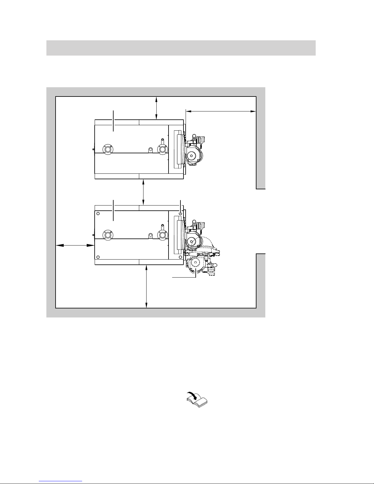
Clearance dimensions
C
A
A
B
b
500 (250)
600
a
500 (50)
A
Boiler
B
Burner
C
Adjustable anti-vibration boiler supports (accessories)
Dimensions in brackets are minimum
clearances.
Dim. a: 500 mm
Dim. b: 400 mm
When using Viessmann accessories for
two-boiler systems, dimensions a and b
apply.
Installation instructions flue gas
header and hydraulic system
connection
Preparing for installation
5592 702 GB
5
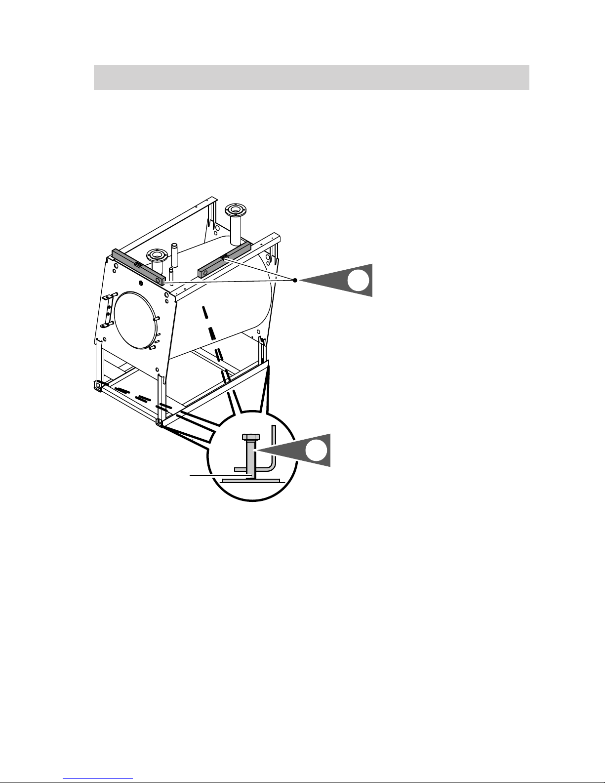
!
Please note
Damage to the flue outlet can
lead to flue gas escaping.
Never lift or move the boiler by
the flue outlet.
Note
A suitable condensate drain (maximum
50 mm above floor level) must be available in the installation room if the boiler
is installed at ground level.
A
2.
1.
1.
Insert adjusting screws A from
above into the base rails.
Note
The adjusting screws are supplied in
the pack.
2. Level the boiler horizontally. Special
foundations are not required.
Note
We recommend the installation of the
boiler on adjustable anti-vibration
supports (accessories).
Insert these from below into the base
rails.
Siting and levelling the boiler
5592 702 GB
6
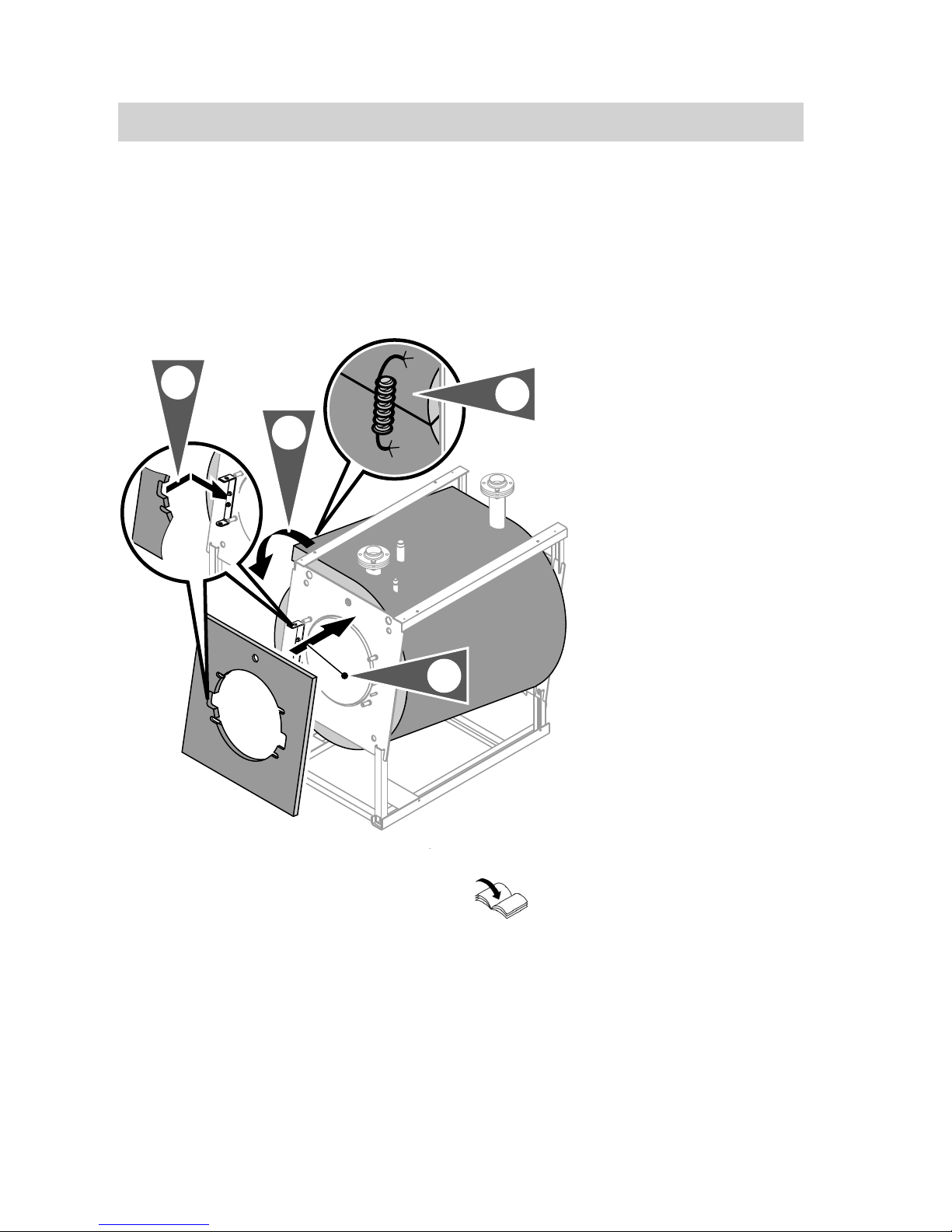
Note
All required components are included in
the carton containing the thermal insulation.
Thermal insulation mats
1.
2.
3.
3.
Note
In the case of balanced flue operation,
attach the ventilation air pipe before fitting the thermal insulation panels.
Installation instructions for accessories for balanced flue operation
Fitting the thermal insulation
5592 702 GB
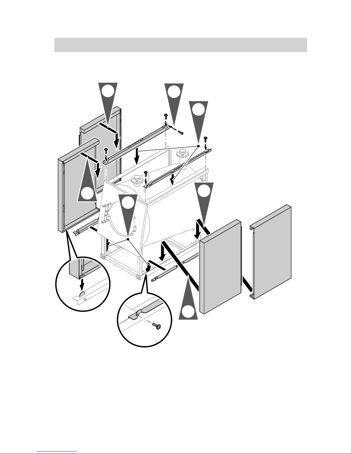
7
Side panels
8x
6 x 10
4x
6 x 10
3.
3.
4.
4.
2.
1.
5. 8x
3.9 x 9.5
Secure the side panels to the upper fixing rails.
Fitting the thermal insulation
(cont.)
5592 702 GB
8
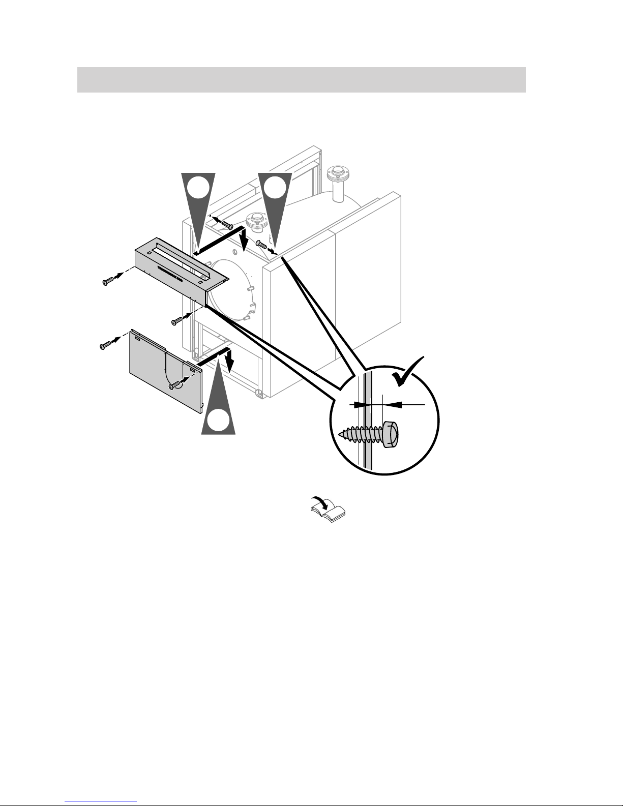
Front panels
3.9 x 9.5
2.
3.
1.
2 mm
3.9 x 9.5
Fully insert the screws into the front
panel top after fitting the boiler temperature sensor and the other sensors (see
page 13).
Note
Prepare an aperture for the ventilation air
pipe in the front panel when operating
the boiler in balanced flue mode.
Installation instructions for accessories for balanced flue operation
Fitting the thermal insulation
(cont.)
5592 702 GB
 Loading...