

Vienna GL70 Installation And Operating Instructions Manual
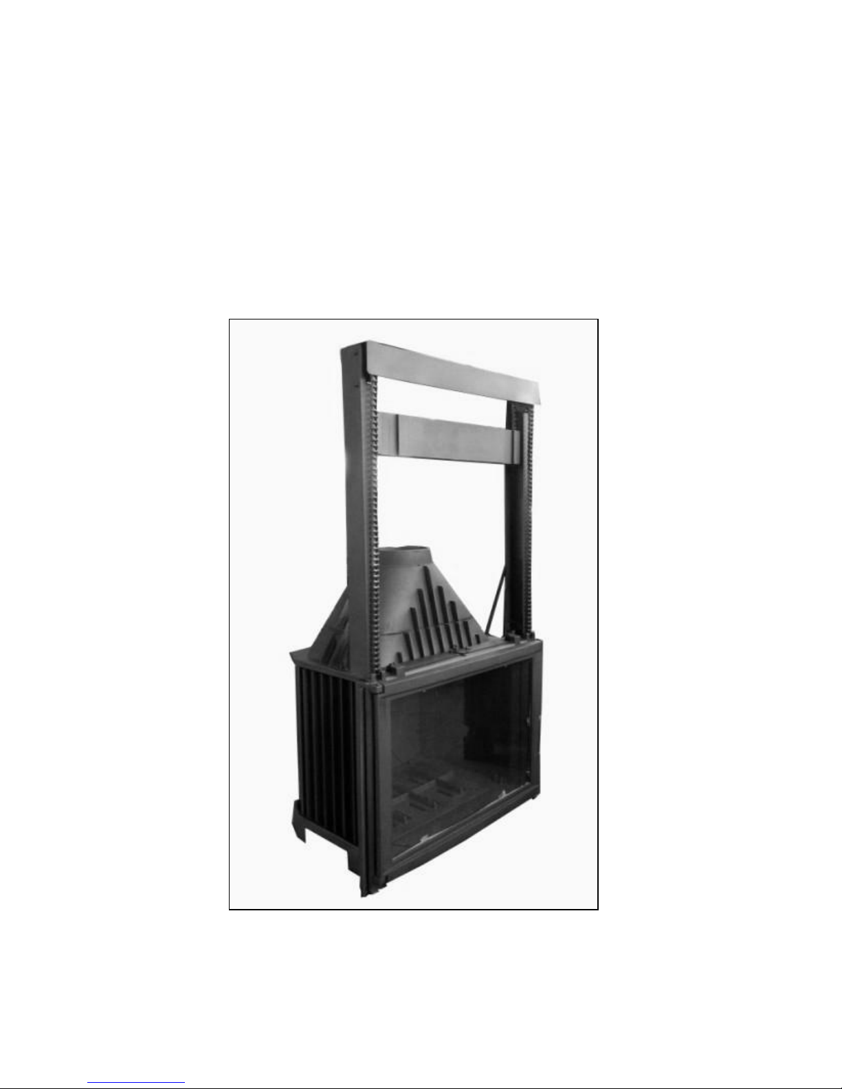
Vienna GL70
Cast Iron Insert Fireplace
Installation and Operating Instructions

Most building regulatory Authorities in Australia require any wood heater installation to
comply with Installation Standard AS/NZS 2918:2001. Different states and councils may have
varying regulations. Check local building regulations before installing the appliance.
The Vienna GL70 has been tested to ensure that it will meet the appropriate safety Standard
requirements if the instructions in this manual are followed. As the safety and emissions
performance can be affected by altering the appliance, no modifications are allowed without
written permission from the manufacturer.
WE RECOMMEND THAT THE INSTALLATION OF THE HEATER BE CARRIED OUT BY A
QUALIFIED INSTALLER.
WARNING: THE APPLIANCE AND FLUE SYSTEM SHALL BE INSTALLED IN ACCORDANCE WITH
AS/NZS 2918:2001 AND THE APPROPRIATE REQUIREMENTS OF THE RELEVANT BUILDING
CODE OR CODES.
WARNING: APPLIANCES INSTALLED IN ACCORDANCE WITH THIS STANDARD SHALL COMPLY
WITH THE REQUIREMENTS OF AS/NZS 4012 & AS/NZS 4013 WHERE REQUIRED BY THE
REGUALTORY AUTHORITY, I.E. THE APPLIANCE SHALL BE IDENTIFIABLE BY A COMPLIANCE
PLATE WITH THE MARKING ‘TESTED TO AS/NZS 4012 & AS/NZS 4013’.
ANY MODIFICATION OF THE APPLIANCE THAT HAS NOT BEEN APPROVED IN WRITING BY
THE TESTING AUTHORITY IS CONSIDERED TO BE IN BREACH OF THE APPROVAL GRANTED
FOR COMPLIANCE WITH AS/NZS 4012 & AS/NZS 4013.
CAUTION: MIXING OF APPLIANCE OR FLUE-SYSTEM COMPONENTS FROM DIFFERENT
SOURCES OR MODIFYING THE DIMENSIONAL SPECIFICATION OF COMPONENTS MAY RESULT
IN HAZARDOUS CONDITIONS. WHERE SUCH ACTION IS CONSIDERED, THE MANUFACTURER
SHOULD BE CONSULTED IN THE FIRST INSTANCE.
CAUTION: CRACKED AND BROKEN COMPONENTS, EG. GLASS PANELS OR CERAMIC TILES,
MAY RENDER THE INSTALLATION UNSAFE.
IMPORTANT INFORMATION
The Vienna GL70 is designed to be installed in a concrete, brick or stone fireplace which is
attached to a chimney and has a non-combustible floor protector.
The flue kit must be installed according to the manufacturer’s instructions. The 7” flue
spigot in the heater must be fitted with a reducer so that it can be installed with a 6”
stainless steel flue system
If the heater is to be installed near combustible materials, it must comply with the
following installation safety clearances.
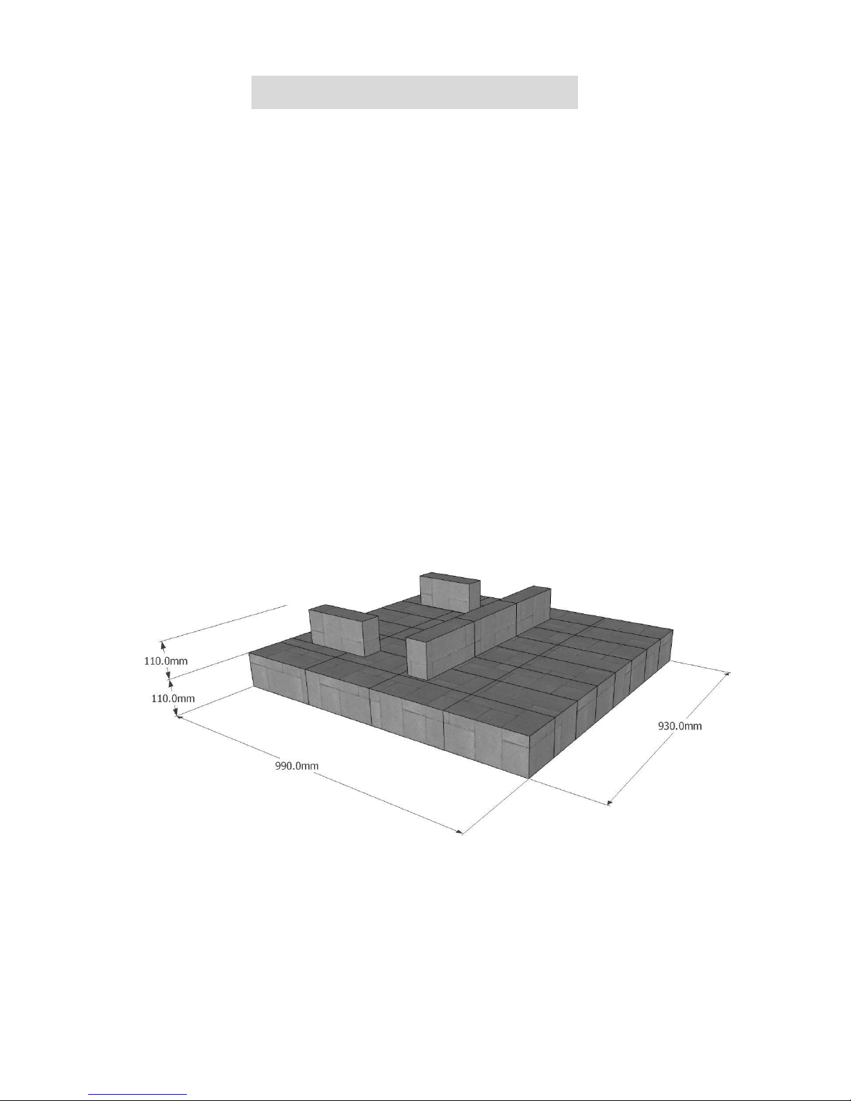
Floor Protector
When installed on a combustible floor, the floor protector beneath the heater should
consistent of standard bricks (225x110x70mm) laid out measuring 930mm wide x 990mm
deep x 110mm high. The heater should then be installed on a second row of bricks 110mm
high with an air gap beneath (one brick under each rear corner of the heater and a single
row along the front). This will result in ventilation gaps beneath the heater measuring
200x110mm on both sides and 440x110mm at the rear of the heater
INSTALLING THE HEATER
 Loading...