

Page 1
Year built:
from 01/2008
en_INT
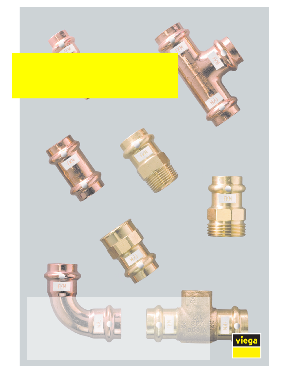
Profipress S
Instructions for Use
Page 2

Profipress S 2 from 24
Page 3
Table of contents
1 About these instructions for use 4
1.1
Target groups 4
1.2
Labelling of notes 4
1.3
About this translated version 5
2 Product information 6
2.1
Standards and regulations 6
2.2
Intended use 7
2.2.1
Areas of use 7
2.2.2
Media 7
2.3
Product description 7
2.3.1
Overview 7
2.3.2
Pipes 8
2.3.3
Press connectors 11
2.3.4
Sealing elements 12
2.3.5
Markings on components 12
2.4
Information for use 13
2.4.1
Corrosion 13
3 Handling 14
3.1
Transport 14
3.2
Storage 14
3.3
Assembly information 14
3.3.1
Mounting instructions 14
3.3.2
Potential equalisation 15
3.3.3
Permitted exchange of sealing elements 15
3.3.4
Space requirements and intervals 16
3.3.5
Required tools 18
3.4
Assembly 19
3.4.1
Replacing the sealing element 19
3.4.2
Bending pipes 20
3.4.3
Shortening the pipes 20
3.4.4
Deburring the pipes 20
3.4.5
Pressing the connection 22
3.4.6
Leakage test 23
3.5
Maintenance 23
3.6
Disposal 24
Table of contents
Profipress S 3 from 24
Page 4
1 About these instructions for use
Trade mark rights exist for this document; for further information, go to
viega.com/legal.
1.1 Target groups
The information in this manual is directed at heating and sanitary pro‐
fessionals and trained personnel.
Individuals without the abovementioned training or qualification are not
permitted to mount, install and, if required, maintain this product. This
restriction does not extend to possible operating instructions.
The installation of Viega products must take place in accordance with
the general rules of engineering and the Viega instructions for use.
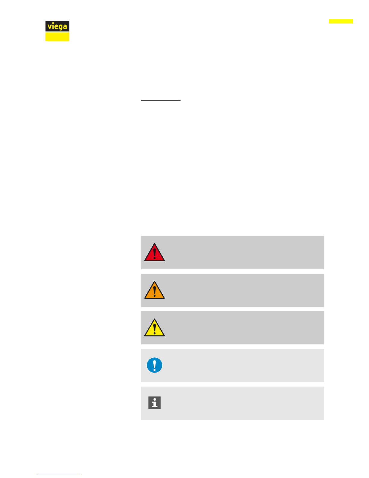
1.2
Labelling of notes
Warning and advisory texts are set aside from the remainder of the text
and are labelled with the relevant pictographs.
DANGER!
This symbol warns of possible life-threatening injury.
WARNING!
This symbol warns of possible serious injury.
CAUTION!
This symbol warns of possible injury.
NOTICE!
This symbol warns of possible damage to property.
This symbol gives additional information and hints.
About these instructions for use
Profipress S 4 from 24
Page 5

1.3 About this translated version
This instruction for use contains important information about the choice
of product or system, assembly and commissioning as well as intended
use and, if required, maintenance measures. The information about the
products, their properties and application technology are based on the
current standards in Europe (e. g. EN) and/or in Germany
(e. g. DIN/DVGW).
Some passages in the text may refer to technical codes in Europe/
Germany. These should serve as recommendations in the absence of
corresponding national regulations. The relevant national laws, stand‐
ards, regulations, directives and other technical provisions take priority
over the German/European directives specified in this manual: The
information herein is not binding for other countries and regions; as said
above, they should be understood as a recommendation.
About these instructions for use
Profipress S 5 from 24
Page 6
2 Product information
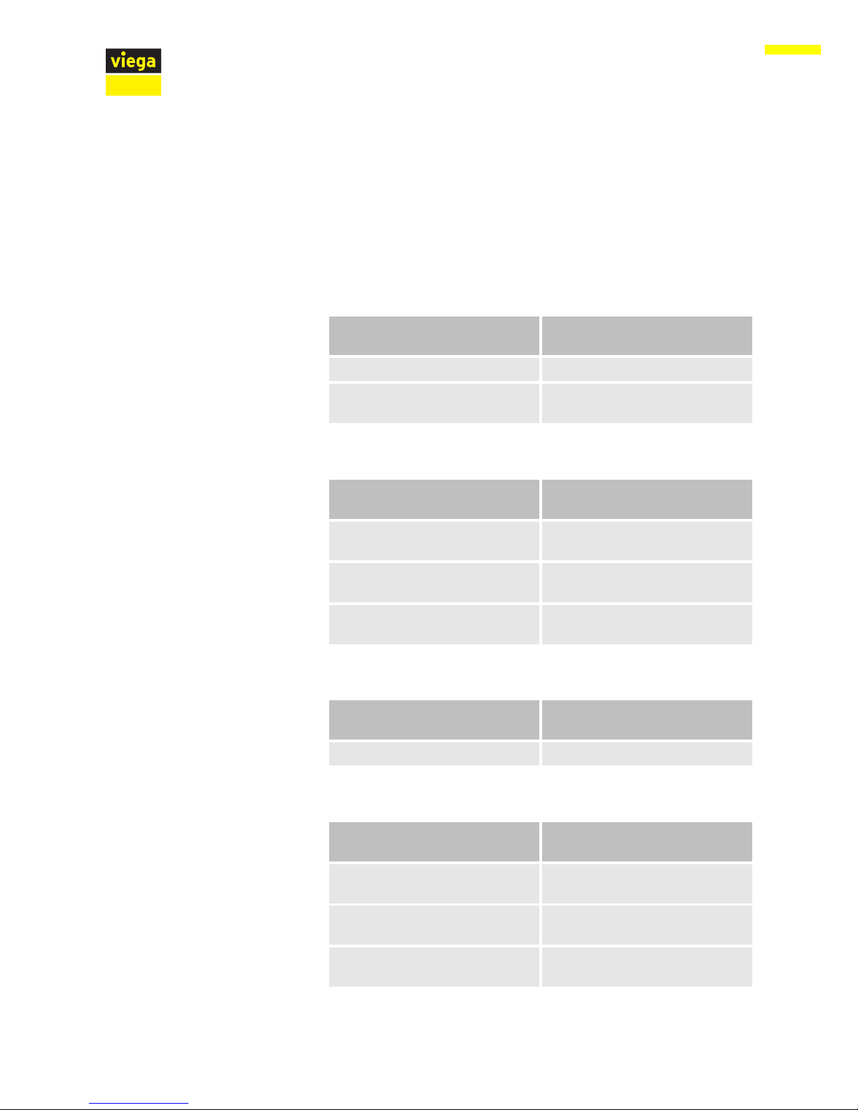
2.1 Standards and regulations
The following standards and regulations apply to Germany / Europe and
are provided as a support feature.
Scope / Notice Regulations applicable in Ger‐
many
Permitted copper pipes DIN EN 1057
Approval of press connectors for
use with copper pipes
DVGW-Arbeitsblatt GW 392
Scope / Notice Regulations applicable in Ger‐
many
Regulations for external corrosion
protection
DIN EN 806-2
Regulations for external corrosion
protection
DIN 1988-200
Regulations for external corrosion
protection
DKI-Informationsdruck i. 160
Scope / Notice Regulations applicable in Ger‐
many
Requirements for material storage DIN EN 806-4, Chapter 4.2
Scope / Notice Regulations applicable in Ger‐
many
Test on a system that is finished
but not yet covered
DIN EN 12976-1
Test on a system that is finished
but not yet covered
DIN EN 12976-2
Test on a system that is finished
but not yet covered
DKI-Informationsdruck i.160
Regulations from section: Pipes
Regulations from section: Corrosion
Regulations from section: Storage
Regulations from section: Leakage test
Product information
Profipress S 6 from 24
Page 7
Scope / Notice Regulations applicable in Ger‐
many
Operation and maintenance of
solar installations
DKI-Informationsdruck i.160
2.2 Intended use
Coordinate the use of the system in units with additives (
e. g. anti-freeze or anti-corrosion agents) in heating water or
for fields of application and media other than those
described with the Viega Service Center.
2.2.1 Areas of use
Do not use the piping system in potable water and gas installations.
Use is possible in the following areas among others:
n Solar installations
n District heat supply systems
n Low-pressure steam systems
n Cooling water pipelines (closed circuit)
2.2.2 Media
The system is suitable for the following media, amongst others:
n Anti-freeze, cooling brines up to a concentration of 50 %
n Steam in low-pressure steam systems
2.3 Product description
2.3.1 Overview
The piping system consists of press connectors for copper pipes and
the corresponding press tools.
Regulations from section: Maintenance
Product information
Profipress S 7 from 24
Page 8
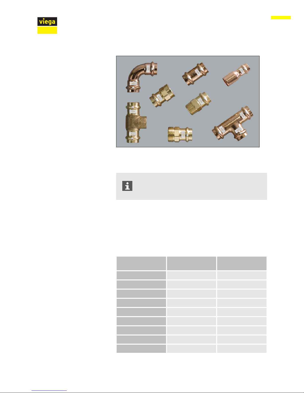
Fig. 1: Profipress S press connectors
The system components are available in the following dimensions:
d 12 / 15 / 18 / 22 / 28 / 35.
Profipress connectors can be equipped with FKM sealing
elements for dimensions above 35 mm.
2.3.2 Pipes
Only copper pipes that comply with the pertinent regulations may be
used, see Ä Chapter 2.1 „Standards and regulations“ on page 6:
Copper pipes in solar installations
d x s [mm] Volume per metre of
pipe [l/m]
Pipe weight [kg/m]
12 x 0.7 0.09 0.22
12 x 1.0 0.08 0.31
15 x 0.8 0.14 0.32
15 x 1.0 0.13 0.39
18 x 0.8 0.13 0.39
18 x 1.0 0.20 0.48
22 x 1.0 0.31 0.59
28 x 1.0 0.53 0.76
35 x 1.2 0.84 1.13
Product information
Profipress S 8 from 24
Page 9

d x s [mm] Volume per metre of
pipe [l/m]
Pipe weight [kg/m]
42 x 1.2 1.23 1.37
54 x 1.5 2.04 2.20
The following instructions amongst others must be observed when
dealing with solar installations:
n The supply line should be installed in an ascending position and the
return flow should be in a descending position, thus allowing the
system to be drained.
n When draining, the heat carrying medium must be collected in a suit‐
able container.
Only pipe clamps with noise insulation inlays should be used.
Observe the general rules of fixing technology:
n Fixed pipelines should not be used as support for other pipelines
and components.
n Do not use pipe hooks.
n Observe distance to connectors.
n Observe the expansion direction – plan fixed and gliding points.
Affix the pipelines in such a way as to de-couple them from the installa‐
tion body, so that they cannot transfer any structure-borne sound,
resulting from thermal expansion or possible pressure surges, onto the
installation body or other components.
Observe the following fixing intervals:
Interval between the pipe clamps
d [mm] Fixing interval between
the pipe clamps [m]
12.0 1.25
15.0 1.25
18.0 1.50
22.0 2.00
28.0 2.25
35.0 2.75
Pipelines expand with heat. Heat expansion is dependent on the mate‐
rial. Changes in length lead to tension within the installation. These ten‐
sions must be equalised with suitable measures.
Laying and fixing pipes
Length expansion
Product information
Profipress S 9 from 24
Page 10

The following are effective:
n Fixed and gliding points
n Expansion equalisation joints (expansion bends)
n Compensators
Heat expansion co-efficient of copper
Material Heat expansion co-effi‐
cient ⍺
[mm/mK]
Example:
Length expansion with
pipe lengths = 20 m
and ΔT = 50 K
[mm]
Copper 0.0166 16.6
Fig. 2: Length expansion of copper pipes
1 - Length expansion ΔI [mm]
2 - Pipe length l0 [m]
3 - Temperature difference Δϑ [K]
The length expansion Δl can be taken from the diagram or can be cal‐
culated using the following formula:
Δl = ⍺ [mm/mK] × L [m] x Δϑ [K]
Product information
Profipress S 10 from 24
Page 11

2.3.3 Press connectors
Press connectors are available in a number of shapes. An overview of
the press connectors suitable for the system can be found in the cata‐
logue.
The press connectors in the Profipress S system consist of the following
materials:
n Copper
n Gunmetal/silicon bronze
Fig. 3: Press connectors
The press connectors have a circumferential bead in which the sealing
element lies. The connector is deformed upstream and downstream of
the bead and permanently connected to the pipe during pressing. The
sealing element is not deformed during pressing.
Fig. 4: SC-Contur
Viega press connectors are equipped with the SC-Contur. The SCContur is a safety technology that is certified by the DVGW and ensures
that the connector is guaranteed to be leaky in an unpressed state. In
this way, inadvertently unpressed connections are noticed immediately
when filling the system.
Viega ensures that inadvertently unpressed connections during installa‐
tion become visible when the system is filled.
n with wet leakage test in the pressure range from 0.1–0.65 MPa (1.0–
6.5 bar)
n with dry leakage test in the pressure range from 22 hPa–0.3 MPa
(22 mbar–3.0 bar)
SC-Contur
Product information
Profipress S 11 from 24
Page 12

2.3.4 Sealing elements
The press connectors are factory-fitted with FKM sealing elements.
Area of use District heat supply Solar installations Low-pressure steam sys‐
tems
Use
District heat supply sys‐
tems behind the external
wall lead-in
Solar circuit —
Operating temperature
[T
max.
]
140 °C
1)
120 °C
Operating pressure [P
max
]
1.6 MPa (16 bar)
0.6 MPa (6 bar) < 0.1 MPa (1 bar)
Comments —
Short-term peak temper‐
atures ≤ 280 °C
—
1)
Consultation with the Viega Service Center required.
2.3.5 Markings on components
The press connectors are marked with a coloured dot. This identifies
the SC-Contur, where the test medium would escape in the case of an
inadvertently unpressed connection.
Fig. 5: Marking
The press connectors are marked as follows:
n white dot
n white rectangle with FKM inscription
Area of use of the FKM sealing element
Markings on press connectors
Product information
Profipress S 12 from 24
Page 13

2.4 Information for use
2.4.1 Corrosion
Galvanised components may not be used in solar installa‐
tions.
Overground pipelines and fittings in rooms do not normally require
external corrosion protection.
There are exceptions in the following cases:
n Contact with aggressive building materials such as nitrite or mate‐
rials containing ammonium
n in aggressive surroundings
If external corrosion protection is required, observe the pertinent guide‐
lines, see Ä „Regulations from section: Corrosion“ on page 6.
Product information
Profipress S 13 from 24
Page 14

3 Handling
3.1 Transport
Observe the following when transporting pipes:
n Do not pull the pipes over the sill. The surface could be damaged.
n Secure pipes during transportation. Pipes may become bent due to
shifting.
n Do not damage the protective caps on the pipe ends and do not
remove them until immediately before mounting. Damaged pipe
ends may not be pressed.
In addition, observe the instructions provided by the pipe
manufacturer.
3.2 Storage
For storage, comply with the requirements specified in the applicable
regulations, see Ä „Regulations from section: Storage“ on page 6:
n Store components in a clean and dry place.
n Do not store the components directly on the floor.
n Provide at least three points of support for the storage of pipes.
n Where possible, store different sizes separately.
Store small sizes on top of larger sizes if separate storage is not pos‐
sible.
In addition, observe the instructions provided by the pipe
manufacturer.
3.3 Assembly information
3.3.1 Mounting instructions
System components may, in some cases, become damaged through
transportation and storage.
n Check all parts.
n Replace damaged components.
n Do not repair damaged components.
n Contaminated components may not be installed.
Checking system components
Handling
Profipress S 14 from 24
Page 15

Do not use Teflon® tape to seal threaded connections in
solar installations, because the change in the creep behav‐
iour of the water glycol mixture may result in gradual leaki‐
ness.
Instead, use properly manufactured hemp packages.
3.3.2 Potential equalisation
DANGER!
Danger due to electrical current
An electric shock can lead to burns and serious injury and
even death.
Because all metallic piping systems conduct electricity,
unintentional contact with a live part can lead to the whole
piping system and components connected to it (e. g. radia‐
tors) becoming energised.
– Only allow electrical work to be carried out by qualified
electricians.
– Always integrate the metallic piping system into the
potential equalisation.
It is the fitter of the electrical system who is responsible for
ensuring that the potential equalisation is tested and
secured.
3.3.3 Permitted exchange of sealing elements
Important instruction
With their material-specific qualities, sealing elements in
press connectors are adapted for use with the corre‐
sponding media and/or the areas of use of the piping sys‐
tems and are generally only certified for them.
The exchange of a sealing element is generally permitted.
The sealing element must be exchanged for a designated
spare part for the intended application Ä Chapter 2.3.4
„Sealing elements“ on page 12. The use of other sealing ele‐
ments is not permitted.
Handling
Profipress S 15 from 24
Page 16

Exchanging a sealing element is permitted in the following situations:
n if the sealing element in the press connector is obviously damaged
and should be exchanged for a Viega replacement sealing element
made of the same material
n if an EPDM sealing element in Profipress connectors should be
exchanged for an FKM sealing element (higher thermal resistance,
e. g. for industrial use)
3.3.4 Space requirements and intervals
Space requirement PT1, type 2 (PT2), PT3-EH, PT3-AH, Pressgun 4B,
4E, 5
d 12 15 18 22 28 35
a [mm] 20 20 20 25 25 30
b [mm] 50 50 55 60 70 85
Space requirement Picco, Pressgun Picco
d 12 15 18 22 28 35
a [mm] 25 25 25 25 25 25
b [mm] 55 60 60 65 65 65
Space requirement press ring
d 12 15 18 22 28 35
a [mm] 40 40 45 45 50 55
b [mm] 45 50 55 60 70 75
c [mm] 35 35 40 40 45 50
Pressing between pipelines
Handling
Profipress S 16 from 24
Page 17

Space requirement PT1, type 2 (PT2), PT3-EH, PT3-AH, Pressgun 4B,
4E, 5
d 12 15 18 22 28 35
a [mm] 25 25 25 30 30 50
b [mm] 65 65 75 80 85 95
c [mm] 40 40 40 40 50 50
Space requirement Picco, Pressgun Picco
d 12 15 18 22 28 35
a [mm] 30 30 30 30 30 30
b [mm] 70 70 70 75 80 80
c [mm] 40 40 40 40 40 40
Space requirement press ring
d 12 15 18 22 28 35
a [mm] 40 40 45 45 50 55
b [mm] 45 50 55 60 70 75
c [mm] 35 35 40 40 45 50
Minimum interval with d 12–35
Press machine
a
min
[mm]
PT1 45
Type 2 (PT2)
50
Type PT3-EH
Type PT3-AH
Pressgun 4E / 4B
Pressgun 5
Picco / Pressgun Picco 35
Pressing between pipe and wall
Distance to walls
Handling
Profipress S 17 from 24
Page 18

NOTICE!
Leaky press connections due to pipes being too short
If two press connectors are to be mounted next to one
another onto a pipe without an interval, the pipe must not
be too short. If the pipe is not inserted up to the prescribed
insertion depth in the press connector during pressing, the
connection may become leaky.
d 12 15 18 22 28 35
Min‐
imum
interval
a [mm]
0 0 0 0 0 10
For the Z dimensions, refer to the respective product page in the online
catalogue.
3.3.5
Required tools
The following tools are required for production of a press connection:
n pipe cutter or a fine-toothed hacksaw
n deburrer and coloured pen for marking
n press machine with constant pressing force
n Press jaw or press ring with corresponding hinged adapter jaw, suit‐
able for the pipe diameter and suitable profile
Fig. 6: Press jaws
Interval between the pressings
Z dimensions
Handling
Profipress S 18 from 24
Page 19

Recommended Viega press machines:
n Pressgun 5
n Pressgun Picco
n Pressgun 4E / 4B
n Picco
n Type PT3-AH
n Type PT3-H / EH
n Type 2 (PT2)
3.4 Assembly
3.4.1 Replacing the sealing element
Do not use pointed or sharp-edged objects to remove the
sealing element. These could damage the sealing element or
bead.
Remove the sealing element from the bead.
Insert a new, undamaged sealing element into the bead.
Ensure that the complete sealing element is in the bead.
Removing the sealing element
Inserting the sealing element
Handling
Profipress S 19 from 24
Page 20

3.4.2 Bending pipes
Copper pipes in the sizes d 12, 15, 18, 22 and 28 can be bent cold with
commercially available bending equipment (radius at least 3.5 x d).
The pipe ends (a) must be at least 50 mm long so that the press con‐
nectors can be mounted properly.
3.4.3 Shortening the pipes
NOTICE!
Leaky press connections due to damaged material!
Press connections can become leaky due to damaged
pipes or sealing elements.
Observe the following instructions to avoid damage to pipes
and sealing elements:
– Do not use cutting discs (angle grinders) or flame cutters
when cutting to length.
– Do not use grease or oils (e. g. cutting oil).
For information about tools, also see Ä Chapter 3.3.5 „Required
tools“ on page 18.
Cut the pipe properly using a pipe cutter or fine-toothed hacksaw.
Avoid grooves on the pipe surface.
3.4.4
Deburring the pipes
The pipe ends must be thoroughly deburred internally and externally
after shortening.
Deburring prevents the sealing element being damaged or the that the
press connector cants when mounted. Use of a deburrer (model 2292.2)
is recommended.
Handling
Profipress S 20 from 24
Page 21

NOTICE!
Damage due to the wrong tool!
Do not use sanding disks or similar tools when deburring.
The pipes could be damaged by these.
Deburr the inside and outside of the pipe.
Handling
Profipress S 21 from 24
Page 22

3.4.5 Pressing the connection
Requirements:
n The pipe end is not bent or damaged.
n The pipe is deburred.
n The correct sealing element is in the press connector.
FKM = matt black
n The sealing element is undamaged.
n The complete sealing element is in the bead.
Push the press connector onto the pipe as far as it will go.
Mark the insertion depth.
Place the press jaw onto the press machine and push the retaining
bolt in until it clicks into place.
INFO! Observe the press tool instruction manual.
Handling
Profipress S 22 from 24
Page 23

Open the press jaw and place at a right-angle onto the connector.
Check the insertion depth using the marking.
Ensure that the press jaw is placed centrally on the bead of the
press connector.
Carry out the pressing process.
Open and remove the press jaw.
ð
Connection is pressed.
3.4.6
Leakage test
The installer must perform a leakage test before commissioning.
Carry out this test on a system that is finished but not yet covered.
Observe the applicable regulations, see Ä „Regulations from section:
Leakage test“ on page 6.
Document the result.
3.5
Maintenance
Observe the applicable regulations for the operation and maintenance
of solar installations, see Ä „Regulations from section: Maintenance“
on page 7.
Handling
Profipress S 23 from 24
Page 24

3.6 Disposal
Separate the product and packaging materials (e. g. paper, metal,
plastic or non-ferrous metals) and dispose of in accordance with valid
national legal requirements.
Handling
Profipress S 24 from 24
 Loading...