

Page 1
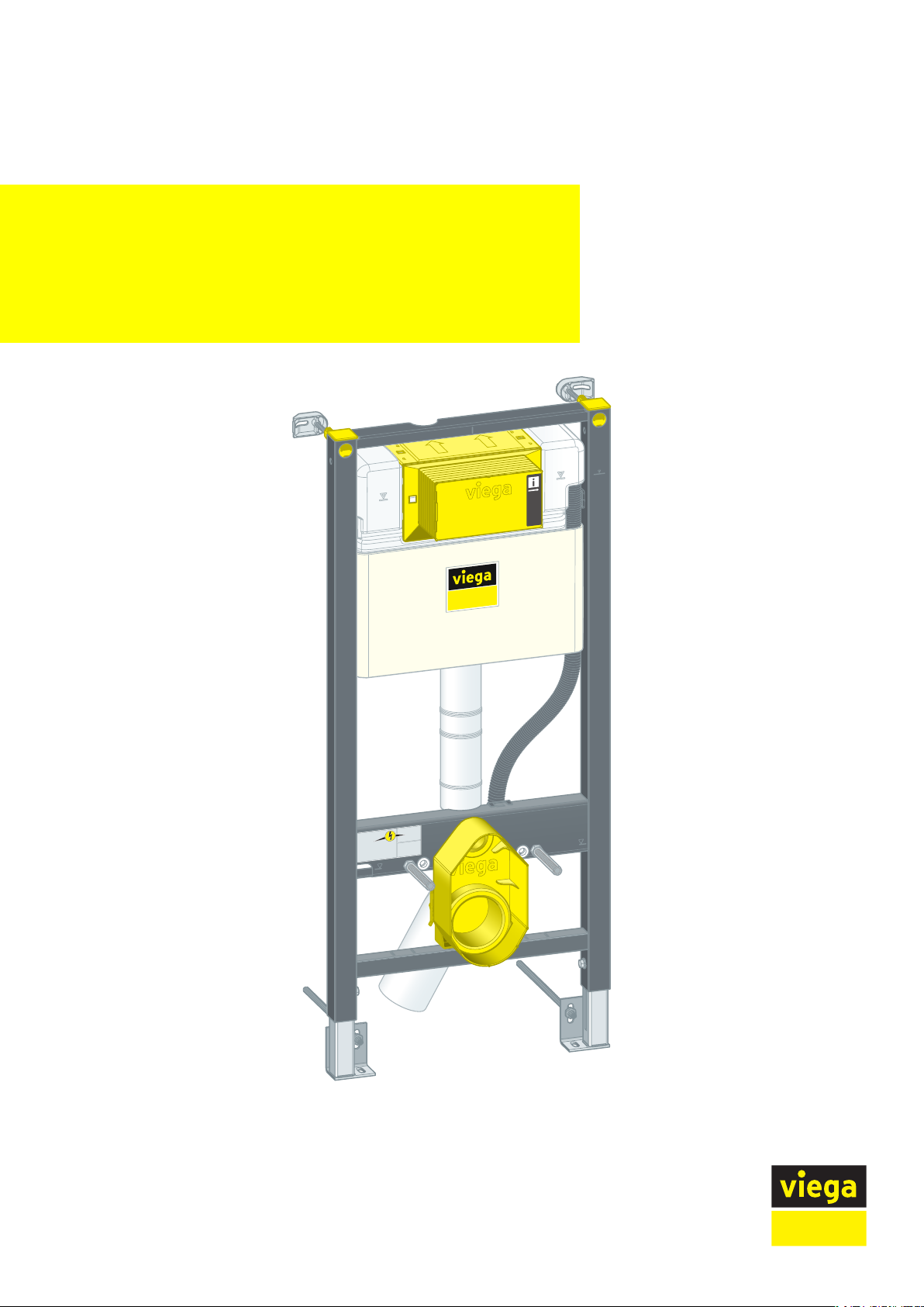
Prevista Dry WC element foot fastening at
rear side 1120 mm
Instructions for Use
for WC flush plates for Prevista
Model Year built:
8525.35 from 04/2019
en_INT
Page 2

Prevista Dry WC element foot fastening at rear side 1120 mm 2 from 24
Page 3
Table of contents
1 About these instructions for use 4
Table of contents
1.1
1.2
1.3
Target groups 4
Labelling of notes 4
About this translated version 5
2 Product information 6
2.1
2.2
2.3
2.3.1
2.4
2.4.1
2.4.2
2.4.3
Standards and regulations 6
Safety advice 6
Intended use 6
Areas of use 6
Product description 7
Overview 7
Compatible components 7
Technical data 8
3 Handling 9
3.1
3.1.1
3.1.2
3.2
3.2.1
3.2.2
3.2.3
3.2.4
3.2.5
3.2.6
3.3
3.4
Assembly information 9
Mounting conditions 9
Installation dimensions 10
Assembly 10
Mounting WC element 10
Connecting concealed cistern 14
Mounting the drain elbow 18
Establish power and water supply (optional) 19
Set and clad the WC element 20
Setting the flush volume 22
Cleaning and maintenance 24
Disposal 24
Prevista Dry WC element foot fastening at rear side 1120 mm 3 from 24
Page 4
About these instructions for use
1 About these instructions for use
Trade mark rights exist for this document; for further information, go to
viega.com/legal.
1.1 Target groups
The information in this instruction manual is directed at the following
groups of people:
n Heating and sanitary professionals and trained personnel
n Drywall builder
Individuals without the abovementioned training or qualification are not
permitted to mount, install and, if required, maintain this product. This
restriction does not extend to possible operating instructions.
1.2
The installation of Viega products must take place in accordance with
the general rules of engineering and the Viega instructions for use.
Labelling of notes
Warning and advisory texts are set aside from the remainder of the text
and are labelled with the relevant pictographs.
DANGER!
This symbol warns of possible life-threatening injury.
WARNING!
This symbol warns of possible serious injury.
CAUTION!
This symbol warns of possible injury.
NOTICE!
This symbol warns of possible damage to property.
This symbol gives additional information and hints.
Prevista Dry WC element foot fastening at rear side 1120 mm 4 from 24
Page 5

1.3 About this translated version
This instruction for use contains important information about the choice
of product or system, assembly and commissioning as well as intended
use and, if required, maintenance measures. The information about the
products, their properties and application technology are based on the
current standards in Europe (e.g. EN) and/or in Germany
(e.g. DIN/DVGW).
Some passages in the text may refer to technical codes in Europe/
Germany. These should serve as recommendations in the absence of
corresponding national regulations. The relevant national laws, stand‐
ards, regulations, directives and other technical provisions take priority
over the German/European directives specified in this manual: The
information herein is not binding for other countries and regions; as said
above, they should be understood as a recommendation.
About these instructions for use
Prevista Dry WC element foot fastening at rear side 1120 mm 5 from 24
Page 6
2 Product information
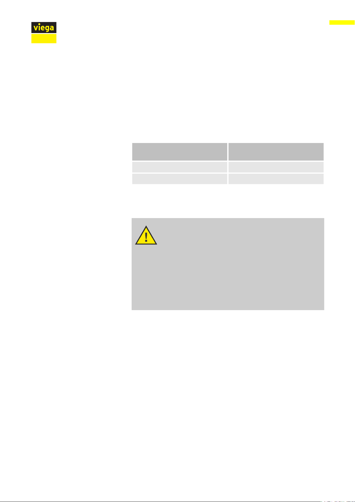
2.1 Standards and regulations
The following standards and regulations apply to Germany / Europe and
are provided as a support feature.
Regulations from section: Fields of application / Mounting conditions
Scope / Notice Regulations applicable in Ger‐
Suitable masonry walls EN 1996-1-1
Suitable concreted walls DIN 1045
Product information
many
2.2 Safety advice
2.3 Intended use
2.3.1 Areas of use
DANGER!
Danger due to electrical current
An electric shock can lead to burns and serious injury and
even death.
– Work on the electrics may only be carried out by trained
electricians.
– Switch off the mains voltage before carrying out work on
electrical parts.
– Switch off the mains voltage before connecting the
power pack.
The Prevista Dry WC element is suitable for mounting on masonry wall
constructions pursuant to the regulations in section Ä „Regulations
from section: Fields of application / Mounting conditions“ on page 6.
Prevista Dry WC element foot fastening at rear side 1120 mm 6 from 24
Page 7
2.4 Product description
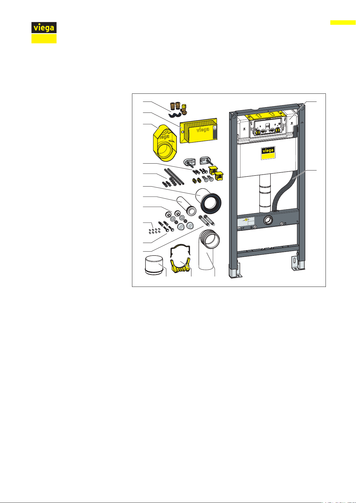
2.4.1 Overview
Product information
Fig. 1: Components
1 concealed cistern 3L
2 Empty pipe for shower WC connection
3 drain elbow
4 Holder for drain elbow
5 reducer
6 threaded rods for wall-mounted WC
(gauges for bore hole 180 or 230 mm)
7 Screws and dowels for fixing in the floor
8 Screws for fixing in support profile
9 Mounting set for WC ceramic
10 flushing pipe
11 WC connection socket with lip seal
12 Fixing set (model 8180.73)
13 Fixing set (model 8570.36)
14 Protective plug for flushing pipe elbow
15 Revision shaft cover
16 Corner valve
2.4.2 Compatible components
The WC element is compatible with all common WC ceramics, even
with larger projection (barrier-free).
Prevista Dry WC element foot fastening at rear side 1120 mm 7 from 24
Page 8
Connection shower WC
Product information
The WC element can be extended by the following compatible compo‐
nents:
n Prevista Dry fixing element
n Prevista shower WC connection set model 8570.64
n Accessory set connection electronic model 8655.11
Mount the components in accordance with the respective instructions
for use.
An additional water and power connection is required to extend the WC
element to the shower WC. Power must be connected on site.
2.4.3 Technical data
Flush volume
Water pressure
Small flush volume Factory setting approx. 3 l
setting range approx. 2–4 l
Large flush volume Factory setting approx. 6 l
setting range approx. 3.5–7.5 l
Water pressure min. 15 kPa (0.15 bar)
Water pressure max. 1000 kPa (10 bar)
Prevista Dry WC element foot fastening at rear side 1120 mm 8 from 24
Page 9

3 Handling
3.1 Assembly information
3.1.1 Mounting conditions
Suitable walls
n Masonry walls
n Concreted walls
The wall constructions must comply with the regulations in section
Ä
tions“ on page 6.
The WC element may only be mounted on even wall surfaces.
Construction height
Handling
„Regulations from section: Fields of application / Mounting condi‐
Actuation versions
With the construction height, the marked height of the upper edge of
the finished floor must be observed.
The WC element can be extended by a remote flush actuation or by an
electronic actuation, as well as by sensitive flush plates. The cables for
these electrical actuation versions must be laid in front of the cladding.
The corresponding empty pipe is required when preparing the remote
flush actuation.
Prevista Dry WC element foot fastening at rear side 1120 mm 9 from 24
Page 10

3.1.2 Installation dimensions
Handling
3.2 Assembly
3.2.1 Mounting WC element
Fig. 2: Dimensional drawing
Masonry and concreted walls
When mounting multiple WC elements with an interval of
> 500 mm, Viega recommends the use of a Prevista Dry
support bracket (model 8570.48). Observe the instructions
for use of the support bracket when mounting.
Prevista Dry WC element foot fastening at rear side 1120 mm 10 from 24
Page 11

Mounting to a masonry wall
9
9
9
9
9
Handling
Determine and mark the fixing points.
n X1: 1100 mm
X2: 460 mm
Drill the holes.
Insert the dowels.
Mount the mounting bracket.
Align and fix the wall brackets.
Determine and mark the fixing points on the wall.
n X3: 388 mm
n X4: 50 mm
Drill the holes.
Insert the dowels.
Prevista Dry WC element foot fastening at rear side 1120 mm 11 from 24
Page 12

Mount the fixing set.
9
Loosen the feet of the element using a fork spanner.
Handling
Adjust the construction height of the element in accordance with the
on-site marking of the upper edge of the finished floor.
n X: 1000 mm
Tighten the feet of the element using a fork spanner.
Set the depth of the element and fasten.
Prevista Dry WC element foot fastening at rear side 1120 mm 12 from 24
Page 13

Handling
Push the mounting bracket through the element on the threaded
rods.
Align the element and use the slide to attach the mounting bracket
to the threaded rods.
Loosely insert the caps.
INFO! Do not press on the caps to engage them.
Re-adjust the alignment of the element using the threaded rods.
Prevista Dry WC element foot fastening at rear side 1120 mm 13 from 24
Page 14

Push the caps down until they engage.
The element is attached to the wall.
ð
Handling
3.2.2 Connecting concealed cistern
Turn the cover plate lock 90° in anti-clockwise direction.
Prevista Dry WC element foot fastening at rear side 1120 mm 14 from 24
Page 15

Remove the cover plate.
Remove the plug.
Insert an empty pipe.
Handling
Fasten the empty pipe in the cistern.
Mount the screw fittings.
Prevista Dry WC element foot fastening at rear side 1120 mm 15 from 24
Page 16

Mount the corner valve.
Fasten the corner valve.
Handling
Connect the corner valve.
Insert the cover plate into the cistern.
Prevista Dry WC element foot fastening at rear side 1120 mm 16 from 24
Page 17

Turn the cover plate lock by 90° in a clockwise direction.
Place the revision shaft on the cover plate.
Handling
To remove the revision shaft, press in the fixing clips at the
side.
Prevista Dry WC element foot fastening at rear side 1120 mm 17 from 24
Page 18

3.2.3 Mounting the drain elbow
"
#
$
Handling
Insert the mounting bracket for the drain elbow.
Insert the drain elbow to the desired depth.
Fasten the drain elbow using the bow.
Fit the site protection.
Prevista Dry WC element foot fastening at rear side 1120 mm 18 from 24
Page 19

3.2.4 Establish power and water supply (optional)
DANGER!
Danger due to electrical current
An electric shock can lead to burns and serious injury and
even death.
– Work on the electrics may only be carried out by trained
electricians.
– Switch off the mains voltage before carrying out work on
electrical parts.
– Switch off the mains voltage before connecting the
power pack.
Lay the power supply for an electric flush plate up to the cavity wall
socket.
Handling
Lay the power pack cable for an electric flush plate through the
empty pipe.
Lay the water pipe for a shower WC through the empty pipe.
Prevista Dry WC element foot fastening at rear side 1120 mm 19 from 24
Page 20

3.2.5 Set and clad the WC element
Turn in the threaded rods by hand.
For 180 mm gauge for bore hole: Counter the threaded rods in front
of the element with a nut.
For 230 mm gauge for bore hole: Counter the threaded rods in front
of and after the element with a nut.
Place the protective caps on the threaded rods.
Corn a suitable gypsum cladding panel at the revision shaft and at
the site protection by applying gentle pressure.
Handling
Cut out the recesses for the site protection, the revision shaft and
the threaded rods.
Prevista Dry WC element foot fastening at rear side 1120 mm 20 from 24
Page 21

Handling
Clad the element with suitable gypsum cardboard cladding panels.
Prevista Dry WC element foot fastening at rear side 1120 mm 21 from 24
Page 22

3.2.6 Setting the flush volume
Requirements:
n The cistern is freely accessible.
n The water supply has been shut off.
n The ceramic has been mounted.
Handling
Fold the tabs forward.
Lift the drain valve.
Remove the drain valve through the revision opening.
Prevista Dry WC element foot fastening at rear side 1120 mm 22 from 24
Page 23

Set the large flush volume at the drain valve.
-
-
Set the small flush volume at the drain valve.
Handling
Prevista Dry WC element foot fastening at rear side 1120 mm 23 from 24
Page 24

Setting the flush flow
Handling
Requirements:
n The drain valve has been dismounted.
n The flushing throttle has been removed.
Unlock the flushing throttle.
Set the flush flow at the throttle.
Lock the flushing throttle.
3.3
Cleaning and maintenance of the concealed cistern
Cleaning and maintenance
The concealed cistern is constantly under mechanical, chemical, and
physical stress. For this reason, the components must be cleaned as
required, and the drain and filling valve seals renewed.
In areas or regions with hard water due to high concentration of calcium
or magnesium salts, there is the risk of limescale deposits developing
on the inlet and drain valves. The valves may have to be replaced,
depending on the extent of the deposits.
3.4
Prevista Dry WC element foot fastening at rear side 1120 mm 24 from 24
Disposal
Separate the product and packaging materials (e. g. paper, metal,
plastic or non-ferrous metals) and dispose of in accordance with valid
national legal requirements.
 Loading...