

Page 1
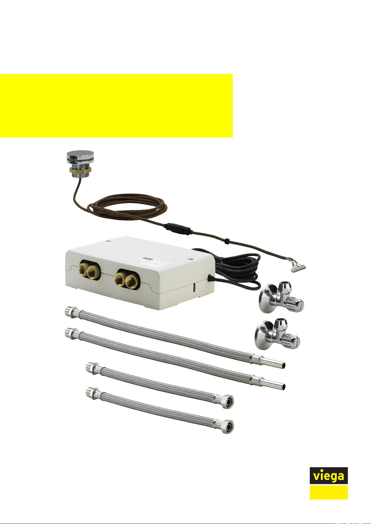
Multiplex Trio E fitting, electronic mixing
unit
Instructions for Use
for filling a bathtub (electronically controlled), in connection with
Multiplex Trio, Multiplex Trio F, Rotaplex Trio or Rotaplex Trio F
(optional electric driven)
Model Year built:
6146 from 01/2010
en_INT
Page 2

Multiplex Trio E fitting, electronic mixing unit 2 from 38
Page 3

Table of contents
1 About these instructions for use 5
Table of contents
1.1
1.2
1.3
Target groups 5
Labelling of notes 5
About this translated version 6
2 Product information 7
2.1
2.2
2.3
2.3.1
2.3.2
2.4
2.4.1
2.4.2
2.4.3
2.4.4
2.5
Standards and regulations 7
Safety advice 8
Intended use 9
Areas of use 9
Maintenance 9
Product description 10
Overview 10
Technical data 10
Functions 12
Control elements and menus 13
Accessories 15
3 Handling 17
3.1
3.1.1
3.1.2
3.2
3.2.1
3.2.2
3.2.3
3.3
3.3.1
3.3.2
3.3.3
3.3.4
3.3.5
3.3.6
3.3.7
3.3.8
3.3.9
3.4
Assembly information 17
Mounting conditions 17
Installation dimensions 19
Assembly 19
Mounting the mixing unit 19
Mounting the control element 23
Connecting the electrical drain (optional) 25
Control 25
Factory settings 25
Setting the water inlet 26
Disabling the temperature safeguard 27
Changing the water inlet 28
Using personal settings 28
Electronic operation of the drain 30
Using the function lock 30
Cleaning functions 31
System diagnosis and statistics 31
Troubleshooting 32
Multiplex Trio E fitting, electronic mixing unit 3 from 38
Page 4

Table of contents
3.5
3.5.1
3.5.2
3.5.3
3.5.4
3.6
Care and maintenance 34
Care tips 34
Maintenance 35
Changing the filters in the corner valves 36
Changing the battery 36
Disposal 38
Multiplex Trio E fitting, electronic mixing unit 4 from 38
Page 5
About these instructions for use
1 About these instructions for use
Trade mark rights exist for this document, further information can be
found at viega.com/legal.
1.1 Target groups
The information in this instruction manual is directed at the following
groups of people:
n Heating and sanitary professionals and trained personnel
n Trained electricians
n Operators
n Consumers
1.2
It is not permitted for individuals without the abovementioned training or
qualification to mount, install and, if required, maintain this product. This
restriction does not extend to possible operating instructions.
The installation of Viega products must take place in accordance with
the general rules of engineering and the Viega instructions for use.
Labelling of notes
Warning and advisory texts are set aside from the remainder of the text
and are labelled with the relevant pictographs.
DANGER!
This symbol warns against possible life-threatening injury.
WARNING!
This symbol warns against possible serious injury.
CAUTION!
This symbol warns against possible injury.
NOTICE!
This symbol warns against possible damage to property.
Multiplex Trio E fitting, electronic mixing unit 5 from 38
Page 6

1.3 About this translated version
This instruction for use contains important information about the choice
of product or system, assembly and commissioning as well as intended
use and, if required, maintenance measures. The information about the
products, their properties and application technology are based on the
current standards in Europe (e. g. EN) and/or in Germany
(e. g. DIN/DVGW).
Some passages in the text may refer to technical codes in Europe/
Germany. These should serve as recommendations in the absence of
corresponding national regulations. The relevant national laws, stand‐
ards, regulations, directives and other technical provisions take priority
over the German/European directives specified in this manual: The
information herein is not binding for other countries and regions; as said
above, they should be understood as a recommendation.
About these instructions for use
Notes give you additional helpful tips.
Multiplex Trio E fitting, electronic mixing unit 6 from 38
Page 7

2 Product information
2.1 Standards and regulations
The following standards and regulations apply to Germany / Europe.
National regulations can be found on the relevant web site of your
country at viega.com/standards.
Regulations from section: Fields of application
Scope / Notice Regulations applicable in Ger‐
Product information
many
Fulfilled requirements in sanitary
fittings
Used in drinking water installa‐
tions
Regulations from section: Mounting the mixing unit
Scope / Notice Regulations applicable in Ger‐
230-V connection VDE 0100 Part 701 (IEC
Regulations from section: Safety
Scope / Notice Regulations applicable in Ger‐
Overflow function EN 274
EN 1111
EN 15091
DIN 1988
EN 806
many
6036-7-701:2006, modified)
many
Regulations from section: Maintenance
Scope / Notice Regulations applicable in Ger‐
many
Thermal disinfection after 72
hours of non-use
Thermal disinfection after 7 days EN 806-5
Multiplex Trio E fitting, electronic mixing unit 7 from 38
VDI 6023
Page 8
2.2 Safety advice
Product information
DANGER!
Danger due to electrical current
An electric shock can lead to burns and serious injury and
even death.
– Work on the electrics may only be carried out by trained
electricians.
– Switch off the mains voltage before opening the casing.
– Switch off the mains voltage before connecting the
power pack.
WARNING!
Risk of scalding from hot water
Excessively hot water can lead to severe scalding, espe‐
cially in the case of children.
Take the following steps to avoid scalding:
– Do not allow children to play with the control elements
unsupervised.
– Disable the temperature safeguard in exceptional cases
only.
– Make sure that no one can come into contact with the
hot water before carrying out thermal disinfection.
WARNING!
Risk of injury due to control via remote access
Controlling the equipment via remote access is permissible
only if there are no persons standing in the direct operating
range.
n The safety shutdown of the inlet does not replace the overflow func‐
tion, see Ä „Regulations from section: Safety“ on page 7.
n Before opening the control casing, switch off the mains voltage and
take steps to prevent accidental re-activation.
n Lay the cable in the control casing in such a way that it touches
nothing.
Multiplex Trio E fitting, electronic mixing unit 8 from 38
Page 9

2.3 Intended use
2.3.1 Areas of use
Product information
Preparation of hot water
Only electronic flowthrough heaters may be used to prepare
hot water.
We recommend the following models:
– Stiebel Eltron DHB-E 18, 21, 24 SL
– Vaillant VED E 24/7
– Flowthrough heaters with comparable features
The product is a mixing fitting for the bathtub with electronic control of
water temperature and filling volume. If an electronic drain / overflow fit‐
ting is installed, filling and emptying of the bathtub can be regulated
using the mixing fitting.
2.3.2
On technical requirements met and the use in drinking water installa‐
tions, see Ä „Regulations from section: Fields of application“ on page 7.
A drain/overflow, water inlet and a pipe interrupter are required for the
complete mounting of the product. Further information on this can be
found at Ä „Required accessories“ on page 15.
Maintenance
Regular maintenance is part of running the system properly Ä Chapter
3.5.2 „Maintenance“ on page 35.
Inform the building owner, the operator or end customer of
the maintenance obligations.
Multiplex Trio E fitting, electronic mixing unit 9 from 38
Page 10
2.4 Product description
2
4
5
8
9
3 6
10
11
13
12
1
7
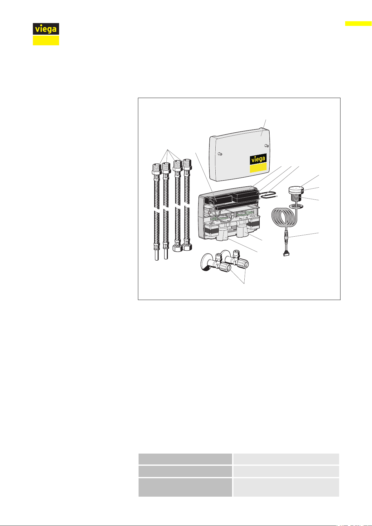
2.4.1 Overview
Product information
2.4.2 Technical data
Fig. 1: Components and scope of delivery
1 - casing upper part
2 - casing
3 - power pack 230 V, with connection cable 3 m
4 - actuator unit for switching between tub and hand shower
5 - actuator unit for the hot and cold water mixer
6 - control with plug contacts for all components
7 - battery for emergency operation
8 - connection hoses
2 x R ½ x DN 12
2 x R ½ x G ½ with union nut
9 - 2 corner valves with filter, R ½ x DN 12
10 - control element
11 - illuminated ring
12 - fixing element with union nut and permanently mounted O-ring
13 - connection cable with plug connector (extendable as an option)
Operating pressure maximum 1 MPa (10 bar)
Recommended flow pressure 0.1–0.5 MPa (1–5 bar)
Pressure difference between
PWC and PWH
maximum 0.1 MPa (1 bar)
Multiplex Trio E fitting, electronic mixing unit 10 from 38
Page 11

Product information
Test pressure 1.5 MPa (15 bar) (1.5 times max‐
imum operating pressure)
Dimensions
Ä
Chapter 3.1.2 „Installation dimen‐
sions“ on page 19
Flow capacity
Warm water temperature T
Ä
Fig. 2 or Ä Fig. 3
≤ 60 °C
max
(scalding protection at 38 °C)
with thermal disinfection:
T
≤ 85 °C
max
Power supply 100–240 V AC, 50/60 Hz
Power consumption Standby operation < 1 W; P
Length of the connection cable
to the control element
IP Code of electronic mixing
3 m (optionally extendable by
another 3 m)
IPX4
unit
IP Code of control element IPX4
max
45 W
Fig. 2: Rate of flow without accessories (corner valves, filling hose, pipe interrupter)
1 - l / min
2 - Δp/bar
Fig. 3: Rate of flow with accessories (corner valves, filling hose, pipe interrupter)
Multiplex Trio E fitting, electronic mixing unit 11 from 38
Page 12

2.4.3 Functions
Basic functions
Product information
The electronic mixing fitting is intended to fill a bathtub with the individ‐
ually desired water temperature. To this end, the mixing fitting has three
memory presets to which the individual preferred settings for water tem‐
perature, filling volume, and filling height of the tub can be saved, ready
to be used for the next bath.
The electronic mixing fitting has been optimised for the control of elec‐
trically operated Viega bathtub drains and overflows. When a manually
operated drain and overflow is used, all functions of the mixing fitting
can be used with the exception of the electronic opening and closing of
the drain.
The following basic functions at the mixing fitting can be controlled
electronically:
Special functions
n Starting and stopping the water inlet
n Setting the water temperature
n Setting the strength of the water inlet
n Switching between bathtub inlet and hand shower
n Opening and closing the bathtub drain (only with electronically con‐
trolled processes; see product portfolio)
n Saving, using, and deleting personal settings
Special functions are those functions not required for the daily use of
the mixing fitting. Special functions are for example basic settings and
maintenance and cleaning functions.
The mixing fitting has the following special functions:
n Diagnosis mode for performing a functionality test
n Performing a thermal disinfection
n Resetting the factory settings
n Enabling the safeguarding function for locking "Thermal disinfection"
and "Reset to factory settings"
n Unlocking the temperature safeguard
n Cleaning mode for short-term disabling of the control element, e.g.
for cleaning
n Automatic opening and closing of the drain fitting if the respective
Viega drain fitting has been mounted (motor-operated valve cone)
Battery emergency operation
The mixing fitting is equipped with a battery to operate the mixing fitting
for approx. 20 minutes in case of power outage.
The battery is recharged immediately after return of the power supply.
If the battery charge drops below a minimum and the user attempts to
operate the mixing fitting, the illuminated ring of the control element will
flash red five times. This indicates that the battery charge is too low to
use the mixing fitting.
Multiplex Trio E fitting, electronic mixing unit 12 from 38
Page 13

Temperature limitation / scalding protection
The mixing fitting is equipped with a scalding protection limiting the
water temperature to 38 °C. This temperature safeguard can be disa‐
bled manually.
2.4.4 Control elements and menus
Operating status
The electronic mixing fitting differentiates between two operating sta‐
tuses:
n Operating status „OFF“ with water supply switched off
n Operating status „ON“ with water supply switched on
The available functions depend on the current operating status.
Product information
Control element
Fig. 4: Control element
Menu structure
The control element can be pressed and turned.
Keep pressed long = Illuminated ring indicates different menu functions.
Press briefly = Water flows in / water inlet stops
Turn = Make various settings (e.g. change water temperature).
Keep the control element pressed to call up the menu. As long as you
keep the control element pressed, the different menu items are shown
successively by way of the different colours emitted by the illuminated
ring. Each colour signifies a different function (see table below).
Colour of
Function
the illumi‐
nated ring
Green Standby mode
Light blue Changing between bathtub inlet
and hand shower
Multiplex Trio E fitting, electronic mixing unit 13 from 38
Page 14

Product information
Red Overcoming the 38 °C tempera‐
ture safeguard / thermal disinfec‐
tion
Purple Saving personal settings
Dark blue Deleting personal settings
Turquoise Enabling the function lock: flash
once = functions available
flash twice = Functions locked
Amber Diagnosis mode
Structure of the operating instructions
All instructions for operating the mixing fitting are of a uniform structure.
Two factors influence the function of the product, and a combination of
these factors brings a result. These two factors are the current oper‐
ating status and the action carried out by the user.
Example:
Operating status „OFF“
Red flashing of the illuminated ring in operating mode
„OFF“ indicates: The battery charge has dropped below
minimum, and the bathtub fitting cannot be controlled any
more (see Ä Chapter 3.5.4 „Changing the battery“
on page 36).
Action Briefly press the control element once.
Result The water starts to flow.
(Automatic stop after max. 45 minutes.)
Multiplex Trio E fitting, electronic mixing unit 14 from 38
Page 15

2.5 Accessories
Required accessories
Product information
The accessories shown here are not included in the scope
of delivery. If required, it must be purchased separately.
Inlet, drain and overflow
A water inlet and a drain/overflow for the tub are required to be able to
install the product completely.
The following four Viega models are optimised for use with an electronic
mixing fitting:
Optional accessories
n Multiplex Trio drain / overflow, model 6175.1
n Rotaplex Trio drain/overflow, model 6175.2
n Multiplex Trio F drain / overflow, model 6148.1
n Rotaplex Trio F drain / overflow, model 6148.2
Pipe interrupter
To ensure that no bath water flows back into the drinking water installa‐
tion, a pipe interrupter must be installed, e. g. the connection set with
concealed pipe interrupter DN 20 in acc. DIN EN 1717, model 6161.86.
A suitable cover rosette for the pipe interrupter must be purchased sep‐
arately.
WLAN module
The mixing fitting can be remotely controlled via the web browser with a
mobile end device (e. g.smartphone, tablet) or via PC (compatible with
Android, iOS or Windows). In addition, you will require the Multiplex
Trio E WLAN module, model 6146.224.
Multiplex Trio E fitting, electronic mixing unit 15 from 38
Page 16

Product information
Extension set for control elements
The extension set model 6146.36 enables installation of a control ele‐
ment on a wall or pre-wall. It contains a concealed socket, an empty
pipe for the connection cable and a fixing set with sealing collar and
chrome-plated cover rosette.
Extension cable
3 m extension cable for the control element: model 6146.22.
Multiplex Trio E fitting, electronic mixing unit 16 from 38
Page 17

3 Handling
3.1 Assembly information
3.1.1 Mounting conditions
Mixing unit
The following requirements exist for the mounting of the mixing unit:
n The mixing unit may only be mounted horizontally or vertically as
n The mixing unit must remain accessible for the purpose of mainte‐
n A 230 V connection is available as power supply, see Ä „Regulations
n The mixing unit may only be so far away from the control element
Handling
shown in the illustration.
nance and the top of the casing must be removable.
Mounting can take place in e. g. a side room or in a pre-wall revision
opening.
from section: Mounting the mixing unit“ on page 7.
that the connection cable (3 m) is not subjected to tensile stress.
If required, the connection cable of the control element can be
extended to 6 m Ä „Optional accessories“ on page 15.
Control element
The following requirements exist for the mounting of a control element:
n The element should be easily reachable from both inside and outside
the tub.
n Fixing can take place on an even surface with the dimensions
60 x 60 mm (e. g. in the pre-wall) or on the tub rim.
n A drill hole with a diameter of 38–40 mm is required for fixing an ele‐
ment.
n If mounting is to take place on the tub rim, we recommend having
the drill hole made by the manufacturer, if possible.
n There must be clearance of at least 40 mm planned behind or below
the mounting area.
n The connection cable must be laid free of tensile stress from the
mounting position of an element to the electronic mixing unit.
If required, the connection cable can be extended from 3 m to 6 m
Ä
„Optional accessories“ on page 15.
n When mounting on the tub rim, it must be ensured that the elements
are never submerged in water. Contact with splash water does not
present a problem.
The following requirements exist for the mounting of the drain / over‐
flow:
n The bathtub is installed.
n The drainage line is installed all the way to the bathtub.
n The underside of the bathtub is accessible.
Multiplex Trio E fitting, electronic mixing unit 17 from 38
Page 18

Pipe interrupter
Handling
To ensure that no bath water flows back into the drinking water system,
a pipe interrupter must be installed in the pipeline between the mixing
unit and the tub inlet.
The following schematic diagram shows what this should look like:
Fig. 5: Mounting scheme with pipe interrupter
It is important that the pipe interrupter is mounted vertically, in the
direction of flow and at least 150 mm above the upper edge of the
bathtub.
The hand shower must also be protected against bath water
flowing back. If no protection is already integrated into the
hand shower being used, it may be necessary to install an
additional pipe interrupter.
Observe the local standards and regulations.
The pipe interrupter is not included in the scope of delivery and must be
ordered separately. Observe the instructions for use of the pipe inter‐
rupter.
Multiplex Trio E fitting, electronic mixing unit 18 from 38
Page 19

3.1.2 Installation dimensions
Handling
Fig. 6: Dimensions
3.2 Assembly
3.2.1 Mounting the mixing unit
Requirements:
n The mounting site must be permanently accessible also after
n The mounting site is such that the planned installation site of the
DANGER!
Risk of electric shock
An electric shock can lead to burns and serious injury and
even death.
– Only allow electrical work to be carried out by qualified
electricians.
– Always de-energise the connection cable before work is
commenced.
mounting, and the casing cover can be removed (e.g. through a revi‐
sion opening).
control elements can be reached with a cable of 3 m length (6 m with
extension).
Multiplex Trio E fitting, electronic mixing unit 19 from 38
Page 20

235
ø8x65
Handling
n A 230 V connection is available as power supply, see Ä „Regulations
from section: Mounting the mixing unit“ on page 7.
n The mixing unit can be mounted with the connections facing either
down or to the left. Other mounting positions or mounting at an
angle impair the functionality of the mixing unit.
Set the 8 mm dowels pursuant to the specified dimensions.
Distance: 235 mm
Drill hole depth: 65 mm
Use a spirit level for horizontal and vertical alignment.
Attach the mixing unit.
INFO! When screwing the hoses to the connections, always apply
the pipe wrench at the bottom end of the inputs and outputs of
the mixing unit. Applying the wrench at the top end may damage
the mixing unit.
Multiplex Trio E fitting, electronic mixing unit 20 from 38
Page 21

Seal the hoses for the water connection (2 x R ½ x DN 12).
Screw the hoses to the hot and cold water inputs.
Mount the corner valves to the hot and cold water installations.
Handling
Unscrew the filter in anti-clockwise direction.
Remove the filter.
Open the water inlet for a few seconds to flush the pipe.
Multiplex Trio E fitting, electronic mixing unit 21 from 38
Page 22

Handling
Screw the filter into the corner valve.
Connect the hoses of the hot and cold water inputs of the mixing
unit to the respective corner valves.
Seal the hoses for connecting the bathtub and the hand shower
(2 x R ½ x G ½ with union nut).
Screw the hoses to the outputs of the mixing unit for bathtub and
hand shower.
Connect the battery to the control electronics.
Make sure that it is properly aligned. Push the battery in until you
feel the plug snap into place.
Multiplex Trio E fitting, electronic mixing unit 22 from 38
Page 23

DANGER! This step must only be done by a qualified electrician!
Connect to the mains.
3.2.2 Mounting the control element
Mounting of the control element is shown here at the bathtub rim by
way of example. For mounting it at another surface, e.g. in the pre-wall,
the same steps and preconditions apply.
Handling
Requirements:
n The planned mounting site of the control elements can be reached
from the mounting site of the mixing unit with a cable of 3 m length
(6 m with extension).
n At the mounting site, there is a drill hole with a diameter of
38–40 mm.
n Behind the drill hole, there is a clearance of at least 40 mm.
Guide the connection cable of the control element through the drill
hole.
Insert the control element in the drill hole.
Multiplex Trio E fitting, electronic mixing unit 23 from 38
Page 24

Handling
Fasten the control element from below with a union nut.
Place the site protection on the control element.
Lead cable with cable lead-in into the recess in the right-hand side
of the casing of the mixing unit.
Connect the plug of the cable leading to the control element to the
connection of the control unit marked "TLI A".
The plug has a groove left and right on one long side which must
face forward when plugging in.
Set the casing lid on the mixing unit and screw it down.
Multiplex Trio E fitting, electronic mixing unit 24 from 38
Page 25

3.2.3 Connecting the electrical drain (optional)
An electrically driven drain and overflow must be used to be able to
open and close the drain using the control element. We recommend one
of the four models mentioned in Ä „Required accessories“ on page 15.
The motor of these models has a connection through which it is con‐
nected to the control of the mixer unit.
Requirements:
n The mixer unit has been mounted.
n The motor-powered drain / overflow has been mounted.
n The mixer unit is accessible and the lid had been removed.
n The motor of the drain / overflow is reachable from the place of
installation of the mixer unit using a 2 m cable (with extension 5 m).
Lead cable with cable lead-in into the recess in the right-hand side
of the casing of the mixer unit.
Handling
3.3
Control
3.3.1 Factory settings
Memory spaces
INFO! The connection of the drain / overflow must take place
before applying mains voltage to the mixer unit so that the drain
can be detected.
Connect plug of the cable with the socket of the control unit marked
"Motor".
The plug has a groove left and right on one long side, this should
face forward when plugging in.
The electronic mixing fitting has three memory spaces to which the
users can save their individual settings. The individual settings include
the water temperature, the strength of the water stream and the water
volume defined via the inflow time.
Multiplex Trio E fitting, electronic mixing unit 25 from 38
Page 26

3.3.2 Setting the water inlet
Handling
In the factory settings, the following values have been assigned to the
memory spaces:
n Memory space 1: 12 °C, 100 % water stream strength, 45 min. inflow
time
n Memory space 2: 25 °C, 100 % water stream strength, 45 min. inflow
time
n Memory space 3: 38 °C, 100 % water stream strength, 45 min. inflow
time
The water inlet takes place pursuant to one of three saved programs:
n Press briefly 1 x = program memory space 1
n Press briefly 2 x = program memory space 2
n Press briefly 3 x = program memory space 3
Starting the water inlet
Stopping the water inlet
Setting the water temperature
If you do not wish to use one of the pre-programmed settings, start one
of the programs and change temperature and inflow time individually.
Operating status „OFF“
Action Briefly press the control element 1 x.
Result The water starts to flow in according to the
settings of program memory space 1.
Operating status „ON“
Action Briefly press the control element 1 x.
Result The water inlet stops.
The fitting has a temperature safeguard at 38 °C to exclude
scalding. For information on how to bypass the temperature
safeguard, see Ä Chapter 3.3.3 „Disabling the temperature
safeguard“ on page 27.
Multiplex Trio E fitting, electronic mixing unit 26 from 38
Page 27

Setting the water stream strength
Handling
Operating status „ON“
Action Turn the control element without pressing it.
Turning clockwise: LED amber = warmer;
turning anti-clockwise: LED blue = colder
Result You have changed the water temperature.
Operating status „ON“
Action Keep the control element pressed and turn it.
Turning clockwise = water stream stronger;
turning anti-clockwise = weaker
Result You have changed the strength of the water
3.3.3 Disabling the temperature safeguard
WARNING!
Risk of scalding from hot water
At water temperatures of 40 °C and up, there is the risk of
scalding, in particular for children. At significantly higher
temperatures, severe injuries from scalding may occur. To
prevent injuries from scalding, the mixing unit comes with a
temperature safeguard permanently pre-set at 38 °C.
Comply with the following measures to prevent scalding:
– After disabling the temperature safeguard, proceed with
particular caution when increasing the temperature.
– Only disable the temperature safeguard if a direct con‐
tact with the water at the water outlet is excluded, and if
there are no small children or handicapped persons in
the bathtub.
– Children must always be supervised in the bathtub so
that they cannot accidentally disable the temperature
safeguard.
stream.
Multiplex Trio E fitting, electronic mixing unit 27 from 38
Page 28

Status The water is running
Action n Turn the control element clockwise until
Result You can now set a temperature beyond 38 °C.
3.3.4 Changing the water inlet
Changing between tub faucet and hand shower
Handling
the LED flashes amber fast.
n Press the control element and keep
pressed until LED emits red light.
n Release the control element.
n Continue turning the control element
clockwise (temperature increases beyond
38 °C).
Operating status „ON“
Action n Keep the control element pressed until the
Result The water inlet changes from water inlet via
3.3.5 Using personal settings
The fitting has three memory spaces to save personal preference set‐
tings for tub filling. The saved settings can be called up directly, and the
tub is filled automatically with the preset values.
Calling up personal data from the memory
Operating status OFF
Action Briefly press the control element 1 x to call up
illuminated ring emits light-blue light.
n Release the control element.
faucet to hand shower or vice versa.
program memory space 1, or briefly press 2 x
to call up program memory space 2, or briefly
press 3 x z to call up program memory space
3.
Result The water flows in according to the saved set‐
tings.
Saving personal settings
Multiplex Trio E fitting, electronic mixing unit 28 from 38
Page 29

Handling
Operating status OFF
Action n Briefly press the operating element (1 x, 2
x or 3 x) to select the desired memory
space.
n Turn the control element to adjust the
water temperature.
Turn clockwise ⇨ for warmer water; turn
anti-clockwise ⇨ for colder water.
n Keep the control element pressed and turn
it to adjust the strength of the water
stream.
n Let the water flow in up to the desired
filling level.
n Keep the control element pressed until the
illuminated ring emits purple light.
n Release the control element.
Result You have saved the water volume currently in
The saved temperature corresponds to the actual tempera‐
ture of the bath water and can significantly deviate from the
target temperature selected last.
Deleting the saved settings (returning to factory settings)
Operating status OFF
Action n Briefly press the operating element (1 x, 2
Result You have reset the selected memory space to
the tub and the mean temperature of the
flown-in water to the selected memory space.
The water inlet stops.
x or 3 x) to select the desired memory
space.
n Keep the control element pressed until the
illuminated ring emits dark blue light.
n Release the control element.
factory settings (also see Ä Chapter 3.3.1
„Factory settings“ on page 25).
The water inlet stops.
Returning all settings to factory settings
Use this function to reset all settings to delivery state (see Ä Chapter
3.3.1 „Factory settings“ on page 25).
Multiplex Trio E fitting, electronic mixing unit 29 from 38
Page 30

Operating status OFF
Action n Keep the control element pressed until the
Result The illuminated ring flashes twice to confirm
3.3.6 Electronic operation of the drain
To use this function, an electrically driven drain and overflow
must be mounted and connected.
Handling
illuminated ring emits dark blue light.
n Release the control element.
successful reset.
You have returned all settings to factory set‐
ting.
Opening / closing the drain by means of the control element
Operating status OFF
Action n Keep the control element pressed until the
Result You have changed the condition of the drain
3.3.7 Using the function lock
Enabling / disabling the function lock
While the function lock is enabled, the functions "Hot water disinfection"
and "Reset to factory settings" are blocked. The function lock can be
used as a child protection or safeguard against unauthorised use.
Operating status OFF
Action n Keep the control element pressed until the
illuminated ring emits blue light for the first
time (after approx. 2 seconds).
n Release the control element.
valve.
illuminated ring emits turquoise light.
n Release the control element.
Result Confirmation with single flash – functions are
available
Confirmation with double flash – functions are
locked
Multiplex Trio E fitting, electronic mixing unit 30 from 38
Page 31

3.3.8 Cleaning functions
Cleaning mode
Handling
Use the cleaning mode to disable the fitting for 45 seconds, for example
to clean the control element, without startup of the water inlet.
Operating status OFF
Action n Keep the control element pressed until the
illuminated ring emits green light.
Keep the control element A pressed until
the illuminated ring emits green light.
n Release the control element.
Result The control element is disabled for 45 sec‐
onds. For this period of time, the illuminated
ring emits green light.
Thermal disinfection
You can disable the cleaning mode before expiry of the 45 seconds by
pressing the control element once more until the illuminated ring goes
out.
The hot water disinfection reliably prevents and build-up of germs in the
fitting.
Operating status OFF
Action n Keep the control element pressed until the
illuminated ring emits red light.
n Release the control element.
Result The fitting undergoes an automatic 5-minutes
disinfection program. A minimal water volume
of water at the maximum supply temperature
is used.
During hot water disinfection, the illuminated
ring of the control element flashes red as a
warning.
3.3.9 System diagnosis and statistics
Using the diagnosis mode
The fitting can carry out an automatic system diagnosis. In this process,
the temperature sensor and the volume flow meter are checked.
Multiplex Trio E fitting, electronic mixing unit 31 from 38
Page 32

Handling
Operating status „OFF“
Action n Keep the control element A pressed until
the illuminated ring emits amber light.
n Release the control element.
Result The inspection program proceeds automati‐
cally.
During the analysis, the illuminated ring of the control element shows
which component of the product is being checked right now.
Indication during the diagnosis:
n Illuminated ring inactive: automatic adjustment of the valves
n Illuminated ring red: hot water valve opens fully (caution: risk of
scalding!)
n Illuminated ring green: hot water valve closes fully
n Illuminated ring blue: cold water valve opens fully
n Illuminated ring inactive: cold water valve closes fully
Indication of the findings
After completion of all diagnosis steps, the illuminated ring of the con‐
trol element indicates the findings.
The following findings can be displayed:
n Illuminated ring flashes amber twice: device functions properly
n Illuminated ring flashes amber three times: temperature sensor
defective – check the connection and replace
n Illuminated ring flashes amber four times: flow sensor defective –
check the connection and replace
3.4 Troubleshooting
Error Cause Remedy
The device is not functioning. The device is not connected to the
mains
Failure of mains power supply Check the terminal box
Power pack not connected to con‐
trol electronics
Control element (TLI) not con‐
nected
Connect the device to the mains
Check or establish the connection
Check or establish the connection
The device switches the water inlet
off too early.
Saved inlet time is set too short Set a longer inlet time Ä Chapter
3.3.2 „Setting the water inlet“
on page 26
Hot and cold water connections
Exchange the connections
mixed up
Multiplex Trio E fitting, electronic mixing unit 32 from 38
Page 33

Error Cause Remedy
Handling
The water temperature is not as
desired.
Hot and cold water pipes mixed
Exchange the connections
up
Hot or cold water valve not fully
Fully open the corner valves
open
Connection hoses kinked Check laying of the hoses
Connection lines clogged Flush the lines
Clean the filter
Reservoir empty Check reservoir
Flowthrough heater not connected Check or establish the connection
Temperature sensor not con‐
nected or defective
Carry out the "System diagnosis"
function Ä „Using the diagnosis
mode“ on page 31
Motor for temperature control not
connected or defective
Carry out the "Diagnosis" function
Ä
„Using the diagnosis mode“
on page 31
Toothed flat belt came off, or
Check toothed flat belt
defective
Pressure difference between cold
Adjust pressure
and hot water inlet too great
(Δ > 1 bar)
No water flow Hot or cold water valve not fully
open
No water supply Check main tap
Supply hoses kinked Check the laying of the supply
Filter clogged Clean the filter
The device is not connected to the
mains
Failure of mains power supply Check the terminal box
Mains adapter not connected to
control
Control unit (TLI) not connected Check or establish the connection
The water flow is not as desired. Hot or cold water valve not fully
open
Supply hoses kinked Check the laying of the supply
Filter clogged Clean the filter
Motor for water flow not con‐
nected, or defective
Fully open the valves
hoses
Connect the device to the mains
Connect 2-pole plug with control
electronics
Fully open the valves
hoses
Check connection and function
Multiplex Trio E fitting, electronic mixing unit 33 from 38
Page 34

Error Cause Remedy
Handling
Toothed flat belt came off, or
defective
Saved flow is too small Reset the function "Factory set‐
Constant water flow Motors not calibrated Carry out the "Diagnosis" function
Valves do not close Carry out the "Diagnosis" function
The water is turned off after a cer‐
tain period of time.
The illuminated ring of the control
element flashes green every 2 sec‐
onds.
On-time limit reached The maximum inlet time is
Individually saved filling volume
reached
Cleaning mode enabled Wait for 45 seconds, or press the
Check toothed flat belt
tings" Ä „Returning all settings to
factory settings“ on page 29
Ä
„Using the diagnosis mode“
on page 31
Ä
„Using the diagnosis mode“
on page 31
45 minutes.
Carry out the function "Deleting
the saved settings" Ä „Deleting
the saved settings (returning to
factory settings)“ on page 29
control element until the green
light goes out
No operation in case of mains
failure
The casing is moist or wet. Impermissible installation situation see label on cover
The control unit (with cable con‐
nection) does not react.
Battery not connected Connect battery to controller
(ACCU)
Battery empty Recharge battery for at least 24
hours
Battery defective Replace battery
Inlets and outlets of valves not
properly sealed
Condensate at the valve bodies no measures required
The control unit is not connected
properly.
The control unit is defective Replace the control unit
The rotating knob does not turn
smoothly
Check the sealing, re-seal of nec‐
essary
Check the connection
Remove and clean the rotating
knob
3.5 Care and maintenance
3.5.1 Care tips
Normal soap or a mild cleaning agent can be used for regular care and
prevention of lime scale on the control elements. Under no circum‐
stances should scouring agent or scratching objects be used.
Multiplex Trio E fitting, electronic mixing unit 34 from 38
Page 35

3.5.2 Maintenance
Replace battery
Handling
Strong stains can be removed using typical household cleaner. It should
be noted that the cleaning agent should be rinsed off after the pre‐
scribed soaking time. There should be no residue on the components.
If the actual charge of the battery drops below a specified minimum, the
fitting is locked and cannot be used any more. To indicate an exces‐
sively low charge of the battery, the illuminated ring of the control ele‐
ment flashes red five times. Excessively low minimum charge of the bat‐
tery can be in indication of a defective battery. To avoid this, replace the
battery in regular intervals.
Depending on the utilisation, the battery should be replaced
every 3 to 5 years.
Changing the filter in corner valves
System diagnosis
Thermal disinfection
For a description of the replacement of the battery, see Ä Chapter 3.5.4
„Changing the battery“ on page 36.
Depending on the local water quality, the filters in the corner valves
must be cleaned or replaced regularly. At commissioning, specify a
maintenance interval which is in keeping with the local water quality.
For a description of the filter replacement, see Ä Chapter 3.5.3
„Changing the filters in the corner valves“ on page 36.
Some of the causes for malfunctions can be identified by system diag‐
nosis. As major (also safety-relevant) functions of the fitting are checked
during the system diagnosis, it should be run in regular intervals.
We recommend to run a system diagnosis every 18 months. When the
device is used very often, reduce the interval correspondingly.
To prevent germ infestation of the water also with infrequent use of the
bathtub, we recommend to carry out a thermal disinfection in the fol‐
lowing cases and intervals:
n after the bathtub has not been used for 72 hours, see Ä „Regula‐
tions from section: Maintenance“ on page 7
n otherwise after 7 days at the latest, see Ä „Regulations from section:
Maintenance“ on page 7
Multiplex Trio E fitting, electronic mixing unit 35 from 38
Page 36

3.5.3 Changing the filters in the corner valves
Depending on the local water quality, the filters in the corner valves
need to be changed regularly.
Requirements:
n The corner valves are accessible (e.g. through a revision opening).
n Two spare filters are available.
Turn off the water supply to the mixing unit.
Unscrew the filter in anti-clockwise direction.
Remove the filter.
Handling
3.5.4
Insert a new filter.
Tighten the filter in clockwise direction.
Turn the water supply to the mixing unit back on.
Changing the battery
The battery of the mixing unit should be replaced regularly
because the mixing fitting cannot be used if the battery
charge is below a specified minimum.
Multiplex Trio E fitting, electronic mixing unit 36 from 38
Page 37

Requirements:
n The mixing unit is accessible (e.g. through a revision opening).
n The lid of the mixing unit can be removed.
n A spare battery is available.
Loosen the screws of the casing cover and retain.
Remove the casing cover.
Handling
Pull the plug straight away from the control to disconnect.
Remove the battery from the mixing unit and dispose of properly.
Multiplex Trio E fitting, electronic mixing unit 37 from 38
Page 38

Handling
Insert the new battery.
Connect the battery to the control electronics.
Make sure that it is properly aligned. Push the battery in until you
feel the plug snap into place.
3.6
Place the casing cover in the mixing unit and re-fasten it.
Disposal
Separate the product and packaging materials (e. g. paper, metal,
plastic or non-ferrous metals) and dispose of in accordance with valid
national legal requirements.
Multiplex Trio E fitting, electronic mixing unit 38 from 38
 Loading...