

Page 1
Installation Guide
rogerseller.com.au
Dimensions are approximate. Information provided in this installation guide is representative of the
actual product available at the time of printing. Due to our policy of continuous product development,
the design and speciications depicted are subject to change without notice. Please conirm all
particulars with your sales consultant prior to purchase.
Viega More
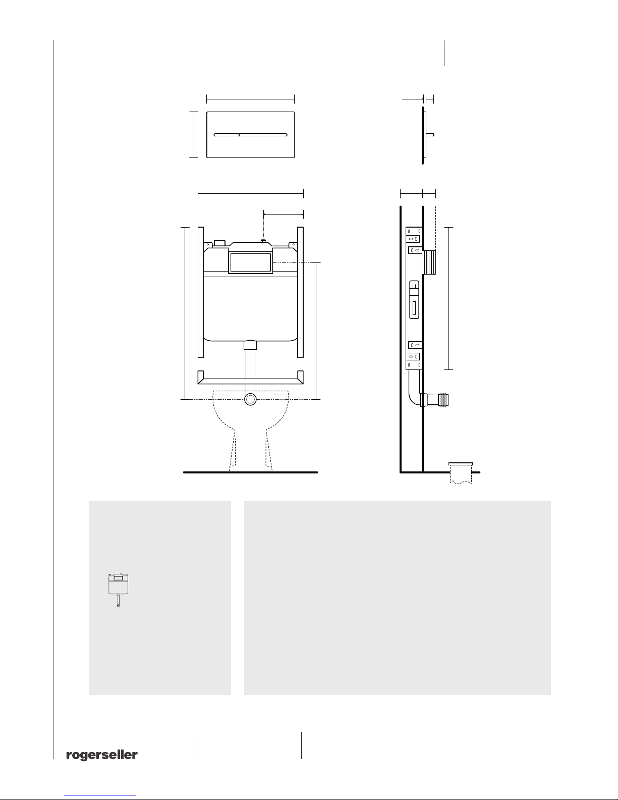
210
560
58 0-74 0
911
700
A
271
140
174.5
90
B
Please note
• Minimum cavity depth is 90mm
• The cistern has a 1/2’ Female connection
located at point A
• Finished wall lining (located at point B)
must have a thickness of 17mm (min) –
130mm (max)
• A lush pipe support bracket is supplied
with this cistern
• Access to the internal workings of
the cistern is only available through
the front mounted push plate
• To lush mount the push plate with the
inished tiled surface a lush mounting
plate (230250) is required
• WELS 4 Star 4.5/3 litres dual lush cistern
• All dimensions are in millimetres
• Full installation instructions come
with the product
Important
Flush-mount push plate installation requires
the purchase of a Flush Mounting Plate (sold
separately). This mounting plate is required
at rough-in prior to tiling. The installation
requirements for both cistern and push plate
are dierent for lush mounting. Please refer
to lush mounting plate installation guide
prior to purchase and installation.
Viega Mono Slim 4.5L
in wall cistern and more
104 push plate
230323
Page 2
Installation Guide
rogerseller.com.au
Dimensions are approximate. Information provided in this installation guide is representative of the
actual product available at the time of printing. Due to our policy of continuous product development,
the design and speciications depicted are subject to change without notice. Please conirm all
particulars with your sales consultant prior to purchase.
Viega More
1 2 3 4
5 6 7 8
10 11 12
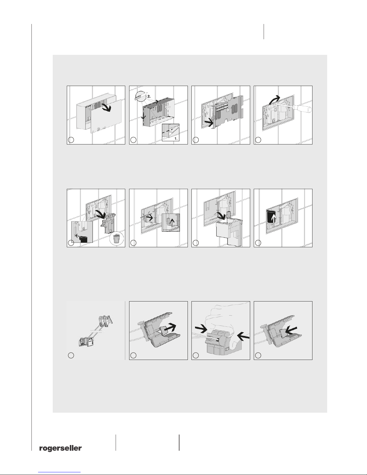
STEP 01
1. Remove the duct cover. 2. Cut in the corners of the duct
as far as the surface of the wall
then fold up the sides. The edge
of the duct must now be flush
with the surface of the wall.
3. Remove internal cover. 4. Unlock the mechanism.
STEP 02
(Bowden wire unit)
9. Remove the Bowden wire
unit from the push plate box.
10. Remove the bracket from
the underside of the Bowden
wire unit.
11. Press the Bowden wire
unit together.
12. Replace the bracket onto
the underside of the Bowden
wire unit.
5. Unhook the bar from the drain
valve. Take the mechanism out
of the front. You can dispose
of these parts.
6. Press the clip of the spacing
element together and remove
the spacer through the top.
7. The spacer can be removed
through the front.
8. Pull the drain valve upwards.
9
Page 3

Installation Guide
rogerseller.com.au
Dimensions are approximate. Information provided in this installation guide is representative of the
actual product available at the time of printing. Due to our policy of continuous product development,
the design and speciications depicted are subject to change without notice. Please conirm all
particulars with your sales consultant prior to purchase.
Viega More
13 14 15 16
18 19 2017
STEP 03
13. Slide the Bowden wire unit
onto the drain valve form the
left-hand side until it snaps
into place.
14. Replace the spacer into the
cistern and attach onto the back
wall of the cistern.
15. Turn the threaded bolts
through 90˚ to secure them
inside the drilled holes in the
duct. The relevant depth of
the threaded bolts should be
taken from the instructions
for use of the actuating panel.
16. Attach the Bowden wire
unit to the rear of the base
plate. Observe colour coding.
Green Bowden wire should
be attached to the place
marked with a green dot.
17. Remove the push plate
from the base plate.
More Series – Remove by hand.
Style Series – Use suction cups
provided.
18. Attach the base plate and
screw it into place with the
screws supplied.
19. Inset the push plate into
the base plate.
20. Style Series – Please keep
the suction caps provided,
they will be needed for future
maintenance.
 Loading...