

Viega ProPress 304 Stainless, MegaPress, ProPress, ProPressG, ProPress 316 Stainless Installation Manual
...Page 1
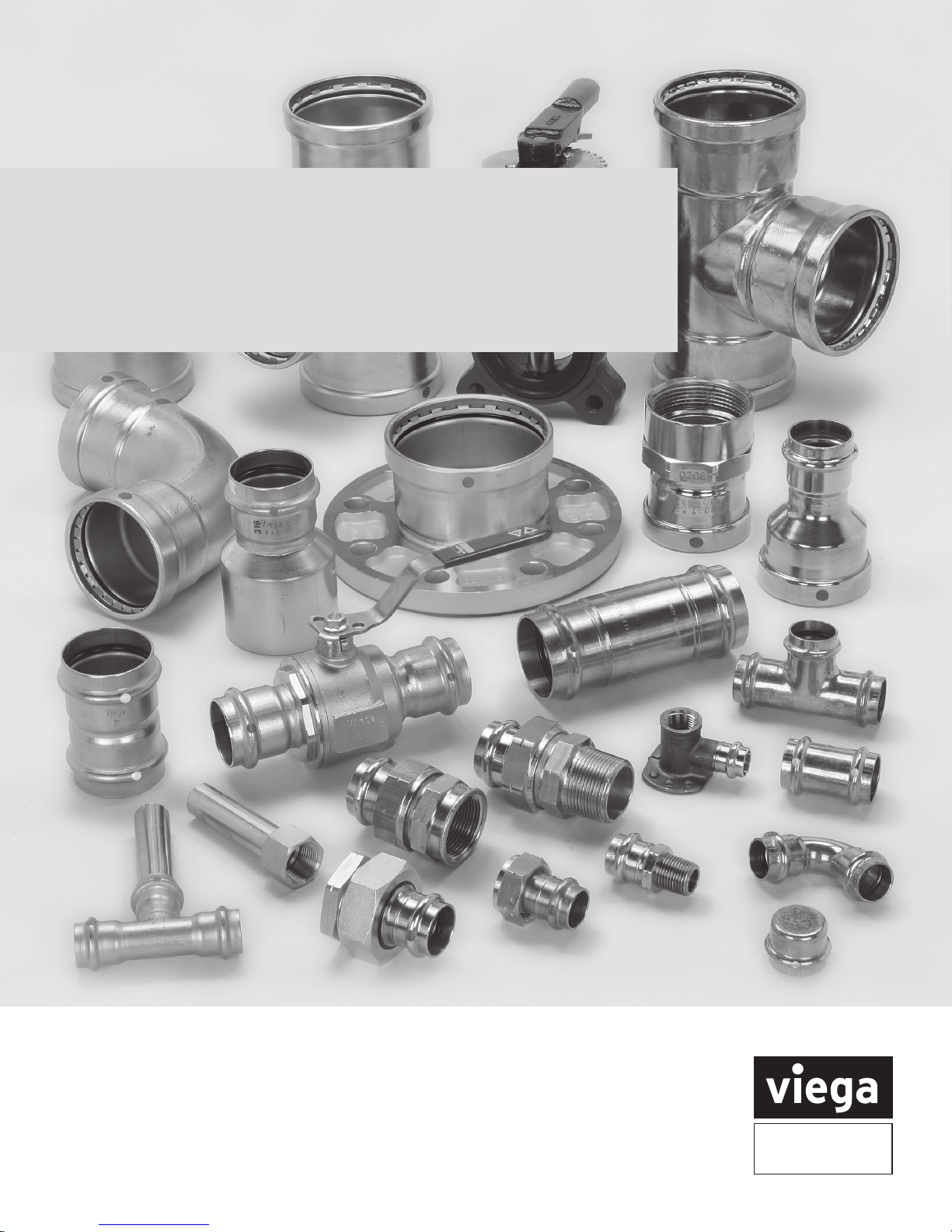
Viega ProPress Systems
Installation Manual
The global leader
in plumbing, heating
and pipe joining systems
Page 2
Heritage of quality, vision for the future
Viega’s heritage of superiority demands nothing
but the best for our customers. Engineered to be
efficient, Viega products perform at the highest
possible level, providing confidence and peace of
mind. Viega is the only manufacturer to offer press
systems in multiple pipe joining materials and, with
a supply chain that can process orders in less than
24 hours, Viega is positioned to provide customers
the best, most versatile support in the industry.
Introducing Viega ProPress systems
Viega ProPress systems are state-of-the-art press
fitting systems that provide economical and reliable
piping installations for the commercial, industrial
and residential markets.
The Systems
Our products are the result of decades of experience
in manufacturing fittings. Viega ProPress systems are
offered in the following configurations:
Viega ProPress: Copper and Zero Lead Bronze
fittings in copper tube size (CTS) with Smart
Connect® feature.
Viega ProPressG: Copper and Bronze fittings for use
with fuel gas in copper tube size (CTS) with Smart
Connect feature.
Viega ProPress for Stainless: 304 and 316
stainless steel pipe and fittings in copper tube
size (CTS) with Smart Connect feature.
Viega ProPress fittings require no soldering or
welding, and thus no fire hazard, which is particularly
important in restoration or retrofit work. The press
fittings are installed with the system pressing tools
(a battery-powered or corded pressing tool).
One squeeze of the trigger makes the connection
on any size tube in four to seven seconds.
Flameless
No flame is required to make the connection. This
eliminates noxious fumes, the need for a hot work
permit and a fire watch.
World’s Largest Selection of Fittings
There are more than 1,400 different engineered
fittings available in a variety of materials,
configurations and sizes.
Professional Appearance
Because there is no buildup of joining material,
exposed threads or tarnish, Viega ProPress
connections have a clean, professional look.
Less Equipment
With Viega ProPress systems there is no need to
buy or carry expensive, cumbersome equipment.
Welding tanks and threading machines are a thing
of the past.
2
IM-PP 724607 0815
Page 3

Contents
1 System Description
1.1 Viega ProPress ................................................................5
1.1.1 Listings and certications ...................................................5
1.1.2 Codes .................................................................5
1.2 Viega ProPressG ..............................................................5
1.2.1 Listings and certications ...................................................5
1.2.2 Codes ..................................................................5
1.3
Viega ProPress for Stainless 304 and 316
1.3.1 Listings and certications ...................................................5
1.3.2 Codes ..................................................................5
1.4 Fitting description ..............................................................6
1.4.1 Viega large-diameter ttings ................................................6
1.4.2 Pipe ...................................................................6
1.4.3 Special features ..........................................................7
1.4.4 Viega Smart Connect feature ................................................7
1.4.5 Sealing elements .........................................................7
1.4.6 Fitting markings ..........................................................8
1.5 Applications ..................................................................9
1.5.1 Commercial and residential ................................................10
1.5.2 Industrial and plant operations ..............................................10
1.5.3 Fire protection systems ...................................................10
1.5.4 Fuel gas systems ........................................................10
..............................................5
2 Tools
2.1 Tools .......................................................................11
2.2 Pressing tools ................................................................11
3 General Installation Instructions
3.1 Tube selection ................................................................12
3.1.1 Viega ProPress ..........................................................12
3.1.2 Viega ProPressG ........................................................12
3.1.3 Viega ProPress for Stainless ...............................................12
3.2 Handling instructions ..........................................................13
3.3 Pressing requirements. . . . . . . . . . . . . . . . . . . . . . . . . . . . . . . . . . . . . . . . . . . . . . . . . . . . . . . . . .13
3.3.1 Minimum distance between ttings ..........................................13
3.3.2 Pressing in tight quarters ..................................................13
3.3.3
3.3.4 Transition connections ....................................................14
3.3.5 Minimum space requirements for 2½" to 4" ProPress ttings ......................15
3.4 Welding, soldering or brazing requirements .........................................17
3.4.1 Viega ProPress to existing brazed tting ......................................17
3.4.2 Viega ProPress to existing solder tting .......................................17
3.4.3 Soldering or brazing near an existing Viega ProPress tting .......................17
3.4.4 Welding adjacent to a Viega ProPress tting ...................................17
3.4.5
Clearance requirements for ProPress rings
Welding in line with a Viega ProPress tting
......................................14
.......................................17
IM-PP 724607 0815
3
Page 4

3.5 General installation requirements .................................................18
3.5.1 Expansion ..............................................................18
3.5.2 Electrical bonding ........................................................18
3.5.3 Piping exposed to freezing temperatures .....................................18
3.5.4 Corrosion protection. . . . . . . . . . . . . . . . . . . . . . . . . . . . . . . . . . . . . . . . . . . . . . . . . . . . . .18
3.5.5 Concealed spaces .......................................................18
3.5.6 Underground installations .................................................18
3.5.7 Pressure testing .........................................................18
3.5.8 Pipe hangers and supports ................................................18
3.5.9 Pressure surges .........................................................19
3.6 Viega ProPress installation requirements ...........................................19
3.6.1 Rotating a pressed tting ..................................................19
3.6.2 Deection ..............................................................19
3.7 Identication .................................................................19
3.8 Viega ProPress ½" to 2" installation ...............................................20
3.9 Viega ProPress XL (Copper) 2½" to 4" installation ....................................21
3.10 Viega ProPress for Stainless ½" to 2" installation .....................................22
3.11 Viega ProPress XL (Stainless) 2½" to 4" installation ...................................23
3.12 Viega ProPressG ..............................................................24
4 Warranty
4.1 Limited warranty for Viega ProPress ttings and valves ...............................25
4.2 Limited warranty for marine and industrial applications ................................26
4
IM-PP 724607 0815
Page 5

1 System Description
1.1 Viega ProPress
Viega ProPress ½" to 4" fittings feature an
EPDM sealing element suitable for many
applications, including:
• Hot and Cold Potable Water
• Rainwater/Gray Water
• Fire Sprinkler
• Chilled Water
• Hydronic Heating
• Compressed Air
• Low-Pressure Steam
• Vacuum
• See Table 1.1 on page 9 for more
applications
1.1.1 Listings and certifications
• NSF 61 Annex G
• IAPMO PS 117
• UL 213
• FM Class 1920
• ICC-ES PMG 1037
• ABS
• CSA MSE 13
1.1.2 Codes
Compliant with:
• ICC International Plumbing Code
• IAPMO Uniform Plumbing Code
• National Standard Plumbing Code
• NFPA 13, 13D, 13R and 54
• ICC International Mechanical Code
• IAPMO Uniform Mechanical Code
1.2 Viega ProPressG
Viega ProPressG ½" to 2" fittings have a
factory-installed HNBR sealing element suitable
for many applications, including:
• Natural Gas
• Propane Gas
• Diesel Fuel
• See Table 1.1 on page 9 for more
applications
1.2.1 Listings and certifications
Viega ProPressG fittings have been listed for
use with fuel gas distribution systems intended
for installations above ground, underground,
indoors and outdoors, for operating pressures not
exceeding 125 psig for use with copper tube ½"
through 2" nominal size.
• CSA LC-4
• IAPMO LC-4
• ICC-ES PMG 1036
1.2.2 Codes
The major codes and standards regulating fuel gas
piping systems include:
• NFPA 54/Z223.1 National Fuel Gas Code
• ICC International Mechanical Code
• IAPMO Uniform Plumbing Code
Other codes include:
• NFPA 58 Liqueed Petroleum Gas Code
• UPC Chapter 12 Fuel Piping
• NFPA 30 Flammable and Combustible
Liquids Code
• NFPA 30A Code for Motor Fuel Dispensing
Facilities and Repair Garages
• NFPA 31 Standard for the Installation of OilBurning Equipment
Note: All systems must be installed per local
code requirements.
1.3
Viega ProPress for Stainless ½" to 4" ttings feature
both EPDM and FKM sealing elements suitable for
many applications, including:
1.3.1 Listings and certifications
1.3.2 Codes
Viega ProPress for Stainless 304 and 316
• Potable Water (316)
• Condenser Water
• Process Water
• RO and DI Water
• Caustic Chemicals
• Compressed Air
• See Table 1.1 on page 9 for more
applications
• NSF-61 G (316 EPDM)
• ABS
• TSSA
• United States Coast Guard
• Lloyd’s Register
• Det Norske Veritas
• ASME B31
• UL 213 (304 FKM ½" to 2")
• IAPMO PS 117 (316 EPDM)
• ICC International Plumbing Code
• SBCCI International Standard Plumbing Code
• IAPMO Uniform Plumbing Code
• PHCC National Standard Plumbing Code
• Florida Building Code, Volume II Plumbing
Code
• Contact your local Viega representative for
details on approvals in your area.
IM-PP 724607 0815
5
Page 6
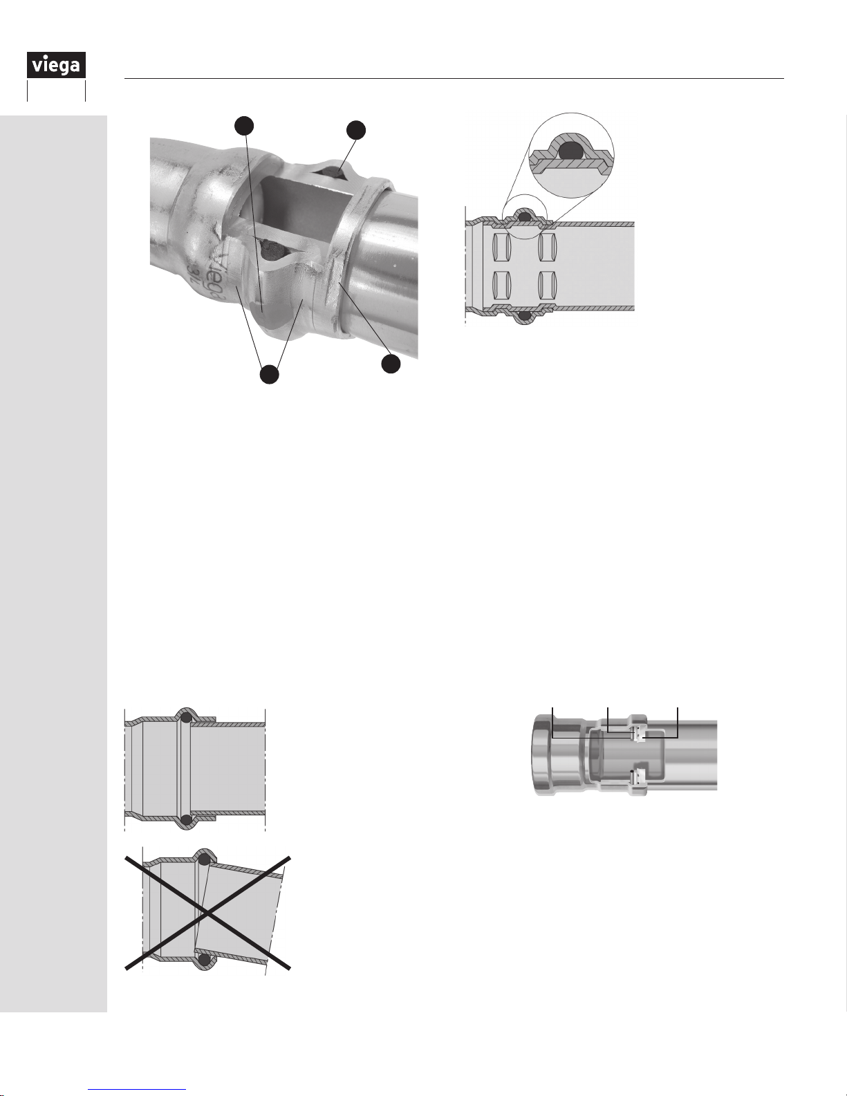
1
2
Viega fittings are
pressed before, after
and on top of the
sealing element in
a single step, which
creates a permanent
connection that
is secure and
guaranteed to last.
4
3
1.4 Fitting description
Viega ProPress ttings are offered in more than
600 congurations in copper, bronze, 304 and 316
stainless steel, including: elbows, couplings, ball
valves, reducers, tees, reducing tees, threaded
adapters, unions, caps and anges. Viega ProPress
ttings for Stainless are designed to be used with
only Viega’s stainless steel pipe.
1. Viega’s unique, patented Smart Connect feature
helps installers ensure that they have pressed
all connections.
2. Viega offers three different sealing elements
to suit virtually any application: EPDM, HNBR
and FKM.
3. Viega’s distinctive hexagonal pressing pattern
bonds fitting and pipe and provides the
mechanical strength for the connection.
4. All Viega ProPress
fittings are designed with
cylindrical pipe guides to
keep the pipe straight and
protect the sealing element
during assembly.
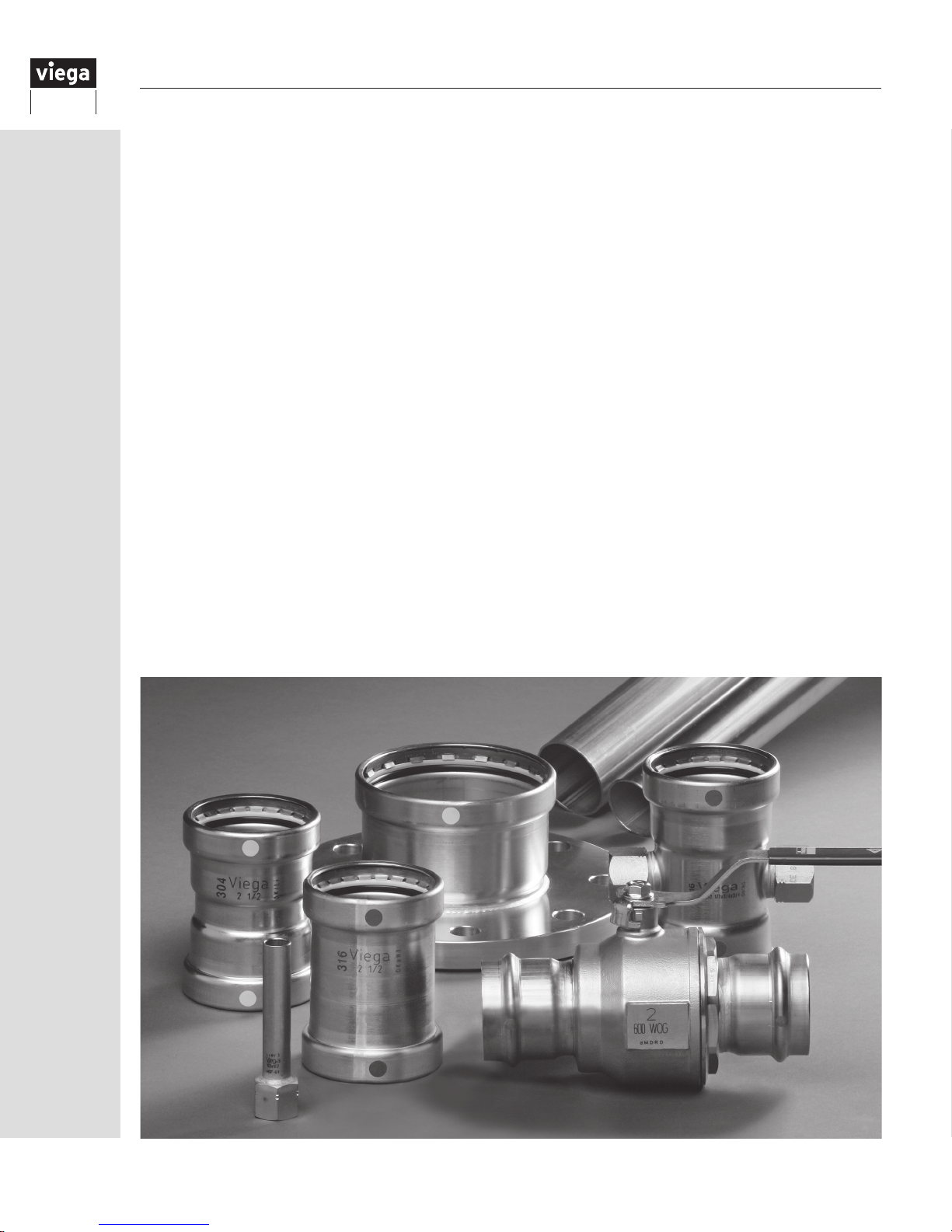
1.4.1 Viega large-diameter fittings
Viega 2½" to 4" ttings feature an EPDM or FKM
sealing element, stainless steel grip ring and PBT
separator ring as shown in Figure 1.1.
The grip ring comes standard in all 2½" to 4"
fittings. The grip ring is a stainless steel ring with
teeth, which grips the tube and ensures that the
fitting is locked securely in place.
The PBT (Polybutylene Terephthalate) separator
ring ensures that the sealing element and grip ring
perform at a maximum capacity by providing a
positive physical separation.
Whether working with stainless steel or copper,
ProPress XL fittings are designed to be pressed
with RIDGID’s XL-C press rings and V2 actuator.
This will produce a non-detachable, permanent
connection.
Figure 1.1
Sealing
Element
PBT
Separator
Ring
Stainless Steel
Grip Ring
6
Fittings that do not
have cylindrical pipe
guides risk making an
unsecure connection.
Without the pipe
guides, installers can
possibly damage the
sealing element.
1.4.2 Pipe
Viega stainless steel pipe is offered in either 304
stainless or 316 stainless to complement the Viega
ProPress for stainless fittings and offer a complete
system solution. Viega stainless steel pipe meets
the requirement of ASTM A312 or ASTM A554 for
schedule 5 304 and 316 stainless steel pipe.
IM-PP 724607 0815
Page 7
1.4.3 Special features
Viega ProPress copper, 316 stainless steel and
Zero Lead bronze fittings meet the federal lead-free
requirements of NSF 61-G through testing under
NSF/ANSI 372 (0.25% or less maximum weighted
average lead content). Fast and easy; one squeeze
of the trigger makes the connection on any size
tube in four to seven seconds.
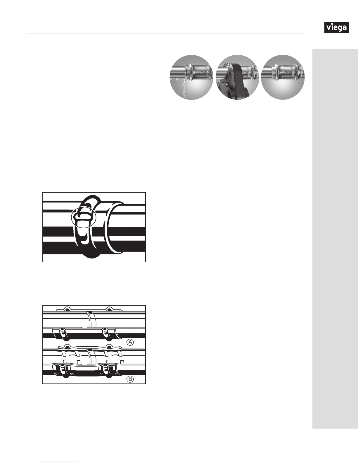
1.4.4 Viega Smart Connect feature
In Viega ProPress ½" to 4" fittings, the Smart
Connect feature (Figure 1.2) assures the escape of
liquids or gases from inside the system past the
sealing element of an unpressed connection. The
function of this feature is to provide the installer
quick and easy identification of connections that
have not been pressed prior to putting the system
into operation (Figure 1.4).
Figure 1.2: The Smart Connect feature of Viega
press fittings is color marked on the bead
When the fitting is pressed (Figure 1.3), a
permanent, sealed, non-detachable, mechanical
connection is created.
Figure 1.3: Section of a press fitting in unpressed
(A) and pressed (B) condition
Unpressed fittings from other manufacturers,
without the patented Smart Connect feature,
may not leak during the initial system pressure
test. However, they can unseat in future system
operation. The Smart Connect feature is designed
to protect from this potential risk.
Figure 1.4
Identify an unpressed
connection during
pressure testing
1
when water flows past the
sealing element.
Upon identification,
use the press tool
to press the fitting,
2
making a permanent leakproof connection.
Viega ProPress
connections are fast,
flameless and guaranteed.
3
1.4.5 Sealing elements
Viega ProPress EPDM sealing element
Operating temperature:
0°F to 250°F (-18°C to 120°C)
Viega ProPress and ProPress for stainless 316
fittings are manufactured with a high-quality EPDM
sealing element installed at the factory. This sealing
element is used mainly in the applications of
potable water, hydronic heating, fire sprinkler and
compressed air installations. EPDM, or ethylenepropylene dienemonomer, is shiny black in color.
The EPDM sealing element is
a synthetically manufactured and peroxide
cross-linked, general-purpose elastomer with
a wide range of applications.
It possesses excellent resistance to aging, ozone,
sunlight, weathering, environmental influences, most
alkaline solutions and chemicals used in a broad
range of applications.
The EPDM sealing element has particularly good
resistance to hot water, making it ideal for seals
and gaskets in heating systems, fittings and
household appliances (e.g. washing machines,
pumps, dishwashers).
All sealing elements are inserted into the fitting using
an H1 Grade lubricant registered with NSF, the
USDA and approved for use under FDA 21 CFR.
Viega ProPress FKM sealing element
Operating temperature:
0°F to 284°F (-18°C to 140°C)
FKM is well known for its excellent resistance
to petroleum products and solvents as well as
exceptional high-temperature performance.
The FKM sealing element is a special-purpose
elastomer typically installed where higher
temperatures are required.
FKM, a fluoroelastomer, is dull black in color. It
possesses excellent resistance to aging, ozone,
sunlight, weathering, environmental influences,
oils and petroleum-based additives. Its superb
resistance to high temperatures and petroleum-
IM-PP 724607 0815
7
Page 8

based additives makes it ideal for seals and
gaskets in solar, district heating, low-pressure
steam and compressed air system fittings. It can
withstand heat spikes up to 356°F.
Viega ProPress HNBR sealing element
This sealing element is used mainly for applications
of natural gas, propane, mixed and manufactured
fuel gases in the vapor state (not in the liquid state).
It is commonly used in fuel oil heating systems.
HNBR, or Hydrogenated Nitrile Butadiene Rubber,
is yellow in color for easy identification.
Ambient operating temperature:
-40°F to 180°F (-40°C to 82°C)
HNBR is widely known for its physical strength and
retention of properties after long-term exposure to
heat, oil and chemicals.
The unique properties attributed to HNBR have
resulted in wide adoption of HNBR in automotive,
industrial and assorted high-performance applications
(e.g. engine seals, grommets, gaskets, fuel system
seals and hoses, transmission system bonded piston
seals, oil field packers and rotary shaft seals).
With its excellent performance for the most
demanding of applications, HNBR is the ideal choice
for applications needing excellent physical properties
as well as oil, heat and/or chemical resistance.
For specific applications, please contact your
local Viega District Manager or contact Viega
at 1-800-976-9819.
1.4.6 Fitting markings
Markings on Viega ProPress fittings include:
• Green Dot: EPDM sealing element and Smart
Connect feature
• Size of tting
• Manufacturer name
• Manufacturer date code
Markings on Viega ProPressG ttings include:
• Yellow Dot: HNBR sealing element and Smart
Connect feature
• CSA: indicates certication to ANSI/CSA LC4
• Yellow rectangle: identies Viega ProPressG
tting as a certied gas or fuel oil tting
• 125G: identies the CSA maximum pressure
rating of the tting for fuel oil or gas
applications
• Size of tting
• Manufacturer name
• Manufacturer date code
Markings on Viega ProPress for Stainless 316
include:
• Green dot: EPDM sealing element and Smart
Connect feature
• Stainless steel alloy number
• Size of tting
• Manufacturer name
• Manufacturer date code
Markings on Viega ProPress for Stainless 304
include:
• White dot: FKM sealing element and Smart
Connect feature
• Stainless steel alloy number
• Size of tting
• Manufacturer name
• Manufacturer date code
8
IM-PP 724607 0815
Page 9
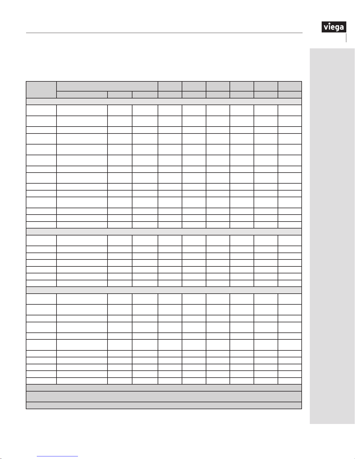
1.5 Applications
Listed below are common applications approved by Viega for Viega ProPress fitting systems.
Table 1.1
Types of Service
Fluids/Water
Hot and Cold
Potable Water
Rainwater/
Gray Water
Fire Sprinkler 175 PSI Note 3 √ √ √
Chilled Water
Hydronic Heating
Cooling Water
Deionized Water 200 PSI 158˚F √
Low-Pressure
Steam
Isopropyl Alcohol 200 PSI 75˚F √
Latex Paint 200 PSI 32˚F-250˚F √
Methyl Ethyl
Ketone
Nitric Acid 10% 200 PSI 73˚F √ √
Phosphoric Acid 25% 200 PSI Ambient √
Parafn Wax 200 PSI 100˚F √
Fuel, Oil and Lubricant
Heating
Fuel Oil
Diesel Fuel 125 PSI Note 3 √ √ √
Ethanol Pure Grain Alcohol 200 PSI Note 3 √ √
Propane Compliant with CSA LC4 125 PSI -40˚F-180˚F √ √
Butane Compliant with CSA LC4 125 PSI -40˚F-180˚F √ √
Kerosene Note 3 68˚F √ √ √
Lube Oil Petroleum Based 200 PSI Note 3 √ √ √
Gases
Compressed Air
Compressed Air
Natural Gas Compliant with CSA LC4 125 PSI -40˚F-180˚F √ √
Oxygen - O
(nonmedical)
Nitrogen - N
Carbon Dioxide
- CO
Ammonia Anhydrous 200 PSI 122˚F √
Acetylene 200 PSI 86˚F √ √
Argon Welding Use 200 PSI Ambient √ √ √ √ √
Hydrogen - H
Vacuum 29.2 in Hg Note 3 √ √ √ √ √ √
1. All systems are recommended to be clearly labeled with the uid or gas being conveyed. For further information please consult Viega Technical Services.
2. All Viega systems must be used with the manufacturer’s recommended sealing element. Contact your local Viega representative or Viega Technical Services for application
temperature, pressure and concentration limits.
3.
System pressure and temperature ranges depend on sealing element.
Up to 50% Ethylene Glycol or
Propylene Glycol solution
2
2
2
2
Keep oil and fat free /
System Operating Conditions
Comments Pressure Temperature FKM EPDM EPDM HNBR EPDM HNBR
200 PSI 32˚F-250˚F √ √
200 PSI Note 3 √ √ √
Ethylene Glycol /
Propylene Glycol
Ethylene Glycol /
Propylene Glycol
Less than 25mg/m
oil content
More than 25mg/m
oil content
non-liquid O
2
3
3
200 PSI Note 3 √ √ √ √
200 PSI Note 3 √ √ √ √
200 PSI Note 3 √ √ √ √
Up to 15
PSI
200 PSI 100˚F √
125 PSI Note 3 √ √ √
200 PSI Note 3 √ √ √ √ √ √
200 PSI Note 3 √ √ √
140 PSI Up to 140˚F √ √ √ √ √
200 PSI Note 3 √ √ √ √ √ √
200 PSI Note 3 √ √ √ √
125 PSI 0˚F-250˚F √ √ √
248˚F √ √ √ √
ProPress
304 Stainless
ProPress
316 Stainless
ProPress ProPressG MegaPress MegaPressG
IM-PP 724607 0815
9
Page 10

1.5.1 Commercial and residential
Viega ProPress systems are approved for numerous
applications in commercial and residential markets
including potable water. “Zero Lead” identifies Viega
products meeting the lead-free requirements of NSF
61-G through testing under NSF/ANSI 372 (0.25%
or less maximum weighted average lead content).
For additional applications please refer to Table 1.1
on page 9 or consult your local Viega District
Manager.
1.5.2 Industrial and plant operations
Viega ProPress systems are also suitable for use
in industrial and plant processes. Primary areas of
application include utility piping, process piping,
cooling water, potable water, and fire sprinkler
systems. Your local Viega District Manager should
be consulted regarding the use of Viega ProPress
systems in areas not covered by Viega literature.
1.5.3 Fire protection systems
Most Viega metal press ttings can be installed
in NFPA 13, 13R and 13D re sprinkler systems.
They are certied for use in “wet” and “dry” re
protection piping in accordance with UL and FM
certications:
• UL VIZM.EX6157 - Fittings, Rubber Gasketed
• UL VIZM7.EX6157 - Fittings, Rubber
Gasketed for Canada
• UL VIZY.EX16017 - Metallic Sprinkler Pipe
• UL VIZY7.EX16017 - Metallic Sprinkler Pipe
for Canada
• FM Approvals Class 1920
1.5.4 Fuel gas systems
Viega ProPressG fittings with HNBR sealing
elements are suitable for applications that include:
• Natural Gas
• Propane Gas
• Mixed Fuel Gases (vapor state only)
• Manufactured Fuel Gases
• Butane
• Fuel Oil Heating Systems
• Carbon Dioxide CO2 (dry)
• Vacuum (up to 29.2 in. Hg)
• Diesel Fuel
• Motor Oil
10
IM-PP 724607 0815
Page 11
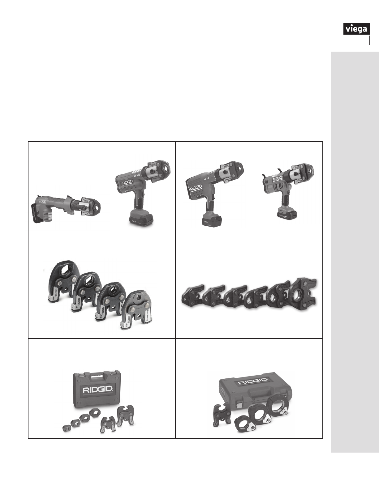
2 Tools
2.1 Tools
Viega recommends RIDGID press tools, Viega
ProPress jaws and ring sets and RIDGID pipe
preparation tools manufactured and sold by The
Ridge Tool Company for use with Viega Systems.
Viega ProPress products carry a warranty against
defects in material and workmanship. The RIDGID
lifetime warranty applies to tools, jaws and press
rings from The Ridge Tool Company. For more
information, contact Ridge Tool Company at
1-888-743-4333 or visit www.RIDGID.com.
Compact Series Press Tools - ½" – 1¼"
2.2 Pressing tools
The following RIDGID pressing tools are available
for use with the Viega ProPress system:
- RP200-B Battery-Powered Press Tool
- RP210-B Battery-Powered Press Tool
- RP330-B Battery-Powered Press Tool
- RP330-C Corded Press Tool
- RP340 Battery-Powered and Corded Press Tool
Standard Series Press Tools - ½" – 4"
RP200-B
Compact Series Press Jaws* - ½" – 1¼"
C1 Compact Series Press Rings* - ½" – 1¼"
V1 Standard Series Press Rings - ½" – 1¼"
V2 Standard Series Press Rings - 1½" – 2"
RP210-B
RP340RP330-B and RP330-C
Standard Series Press Jaws - ½" – 2"
XL-C Press Rings
V2 Actuator - 2½" – 4"
*Compact series press rings and jaws are only for use with compact series press tools.
RIDGID® is a registered trademark of RIDGID
IM-PP 724607 0815
, Inc.
11
Page 12

3 General Installation Instructions
3.1 Tube selection
3.1.1 Viega ProPress
Viega ProPress copper and copper alloy ttings are
compatible with ½" to 1¼" soft copper tube and
½" to 4" hard copper tubing types K, L and M.
All copper tubing that is to be used with Viega
ProPress copper and bronze ttings must comply
with ASTM B88 standards.
Note: Tubing shall be free of surface imperfections
including metal stamped print lines.
3.1.2 Viega ProPressG
Viega ProPressG fuel gas installations can be
made with seamless, drawn copper tubing. These
tubes must comply with the requirements of
ASTM B88.
Types K and L copper tube (ASTM B88) have been
used in fuel gas systems for many years. Type L is
typically used for interior distribution systems and
type K for any underground lines.
Designers and installers should be specific with
size designations in their references and when
ordering. Copper tubing should not be used if the
gas contains more than an average of 0.3 grains of
hydrogen sulfide per 100 standard cubic feet (scf)
of gas (0.7 mg/100 L). Today, federal regulations
limit the amount of hydrogen sulfide allowed in
natural gas transmission. The allowable limits are
below those specified in the model codes and
below the amounts that would adversely affect
copper tubing. Copper tubing can be installed in all
areas of construction, including concealed spaces.
Viega ProPressG and copper tubing is approved
for underground installations. However, any
installations must meet all state and local
codes, including those for underground.
Proper authorization must be obtained prior to
underground installation from the local Authority
Having Jurisdiction. Viega ProPressG and copper
tubing may be installed outside without any
additional corrosion protection.
In residential applications, copper tubing with
Viega ProPressG fittings can be used to run fuel
gas from the meter or source to furnaces, boilers,
gas ranges, water heaters, gas fireplaces, clothes
dryers, outdoor barbecues and decorative lighting.
Copper tubing can be easily installed in wall and
floor cavities. When retrofitting an installation in a
home with copper tubing using Viega ProPressG
fittings is easier, faster and less expensive than
installing threaded steel pipe or CSST.
For commercial construction, copper tubing using
Viega ProPressG fittings may be installed for gas
lines to air handling units, boilers, water heaters
and many other gas appliances. For rooftop
installations, copper tubing with Viega ProPressG
fittings can be installed either on or below the roof.
When installed on the roof, the copper tubing does
not have to be coated or covered since the material
is naturally corrosion resistant.
3.1.3 Viega ProPress for Stainless
Only Viega stainless tubing is approved for
installation with Viega ProPress for Stainless
fittings. This is to ensure reliability and conformity
with the stainless steel system. Viega ProPress for
Stainless pipe comes in sizes ½" to 4".
General
Viega ProPress for Stainless tubing is thicker
than schedule 5, inert gas welded pipes,
meeting ASTM A312, A554 and DIN 1988 wall
thickness requirements.
Delivery condition
All dimensions are delivered in sticks that are nominal
20 ft. in length, with a metallic bare exterior and
interior surface. The sticks are free from annealing
color and corrosion-promoting substances.
All tubing has been tested for leaks and is subject
to continuous quality monitoring, as well as external
monitoring by the material testing office.
12
IM-PP 724607 0815
Page 13

Identification
minimum
distance
Viega ProPress for Stainless pipe is marked and
labeled with the following information along its
entire length:
1. Manufacturer
2. Stock code
1 2 3 4 5 6 7 8 9
VIEGA 87000 ASTM A 312 TP WWW 1/2" x 0.065" ET WLD XXX YYY ZZZ VVV
Identification of ProPress for Stainless
3. Specification standard
4. Material type
5. Nominal diameter x wall thickness
6. Manufacturing information
7. Date of manufacture
8. Batch code
9. Country of origin
3.2 Handling instructions
All Viega ProPress components and associated
piping shall be free from dirt, debris or items that
may interfere with the sealing element and the
press connection.
Viega ProPress sealing elements, separator rings
and grip rings are to be visually inspected prior to
installation to ensure the seal is intact and properly
located within the fitting. See section 1.4.1 on page
6 for more information.
3.3 Pressing requirements
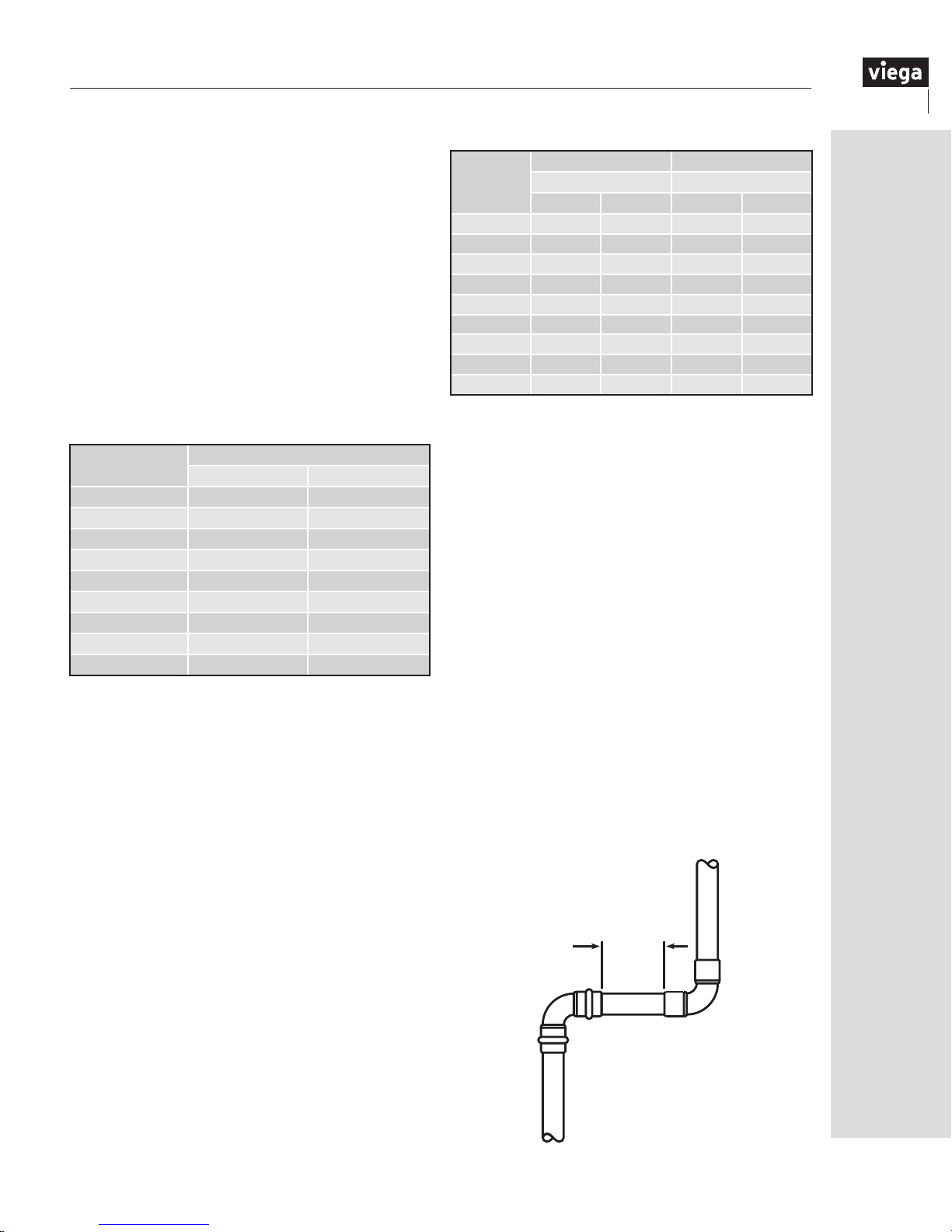
3.3.1 Minimum distance between fittings
To ensure a correct press, a minimum distance
between press fittings must be maintained (refer
to Table 3.1 and Table 3.2). Failure to provide this
distance may result in an improper seal.
Note: Viega ProPress systems include XL (copper)
and XL (stainless) fittings. All XL sizes are 2½" to 4".
For installations where the minimum distance is 0, it
is particularly important to ensure the correct insertion
depth of the tubing into each fitting.
Table 3.1
Minimum distance between two Viega ProPress
Tubing
Diameter
½" 0 0
¾" 0 0
1" 0 0
1¼"
1½" ⅝ 15
press connections
½" to 2"
Minimum Distance
(in)
7
⁄
16
Minimum Distance
(mm)
2" ¾ 20
Table 3.2
Minimum distance between two Viega ProPress
Tubing
Diameter
2½" ⅝ 15
XL (copper) press connections
Minimum Distance
3" ⅝ 15
4" ⅝ 15
2½" to 4"
(in)
Minimum Distance
(mm)
10
minimum
distance
IM-PP 724607 0815
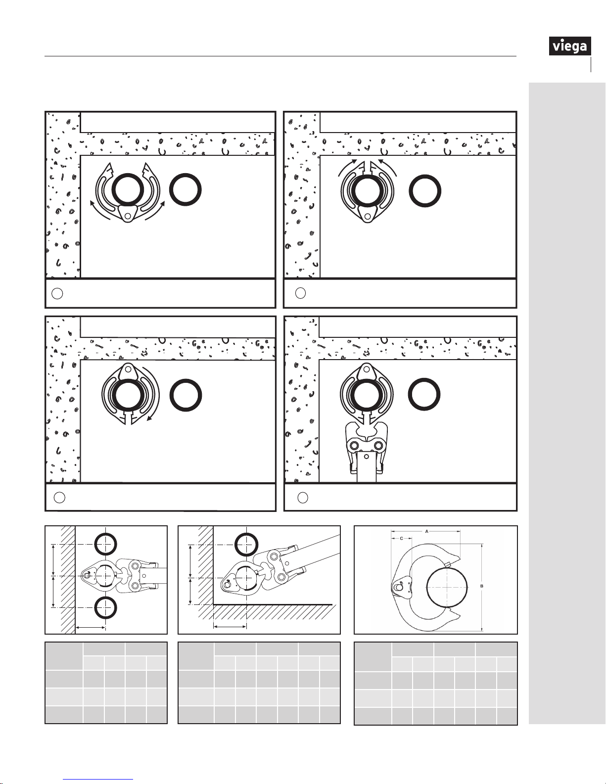
3.3.2 Pressing in tight quarters
The minimum distance between piping, or the piping
and the wall/ceiling construction, must be taken into
consideration in the planning phase for a problemfree work process. The following figures illustrate the
clearance requirements for the jaws and fittings and
the procedure for pressing fittings in tight quarters.
13
Page 14

A
A
Pressing with standard jaws
clearance requirements
Pressing with compact jaws clearance
requirements
B
A
Tube
Diameter
A minimum B minimum
inch mm inch mm
½" ¾ 19 1⅝ 41
¾" ⅞ 22 2⅛ 54
1" 1 26 2½ 64
1¼" 1⅛ 29 2⅞ 73
1½" 1¾ 45 3½ 89
2" 2 51 4⅜ 111
C
20°
B
Tube
Diameter
A
minimumBminimumCminimum
inch mm inch mm inch mm
½" ⅞ 23 1⅜ 35 2½ 64
¾" 1 26 1½ 38 2½ 64
1" 1⅛ 29 1¾ 45 3 76
1¼" 1¼ 32 2¼ 57 3⅛ 80
1½" 1⅞ 48 2½ 64 3¾ 95
2" 2⅛ 54 3⅛ 80 5 127
B
A
Tube
Diameter
A minimum B minimum
inch mm inch mm
½" ¾ 19 2 51
¾" ⅞ 22 2⅜ 60
1" ⅞ 26 2⅝ 67
1¼" 1⅛ 28 3⅛ 85
C
20°
B
Tube
Diameter
A
minimumBminimumCminimum
inch mm inch mm inch mm
½" ⅞ 23 1⅜ 35 2½ 64
¾" 1 26 1½ 38 2¾ 70
1" 1⅛ 29 1⅝ 41 3 76
1¼" 1⅝ 39 2⅛ 53 3⅜ 85
3.3.3
Clearance requirements for ProPress rings
Ensure that the space required for system pressing
tools is available if Viega ProPress fittings will be
executed immediately upstream and downstream
from ceiling penetrations.
14
3.3.4 Transition connections
Threaded connections
The Viega ProPress systems ½" to 4" can be
joined with off-the-shelf threaded fittings made
of non-ferrous metals.
In this regard:
1. The threaded connection is made first.
2. The press fitting is made.
This process avoids unnecessary torsion.
Flange connections
When using Viega flanges, bolt the flange end in
place prior to pressing the fitting to the tubing.
IM-PP 724607 0815
Page 15
C
A
B
3.3.5 Minimum space requirements for 2½" to 4" ProPress fittings
V2 Pressing in tight quarters
Wrap the actuator ring around the press tting with the
1
opening facing away from you.
Rotate the actuator ring until the press jaw receptacle is
3
facing toward you.
Close the actuator tight around the tting.
2
Properly insert press jaws and begin the press
4
tting procedure.
Procedure for laying the XL (copper and stainless) press ring around the XL (copper and stainless) Viega ProPress fitting with minimum space requirements.
B
B
B
A
V2 Actuator V2 Actuator
Tube
Diameter
A B
inch mm inch mm
2½" 4⅛ 105 6 152
3" 4⅜ 111 7 178
4" 5 127 8 203
C
Tube
Diameter
2½" 4⅛ 105 6 152 4½ 114
3" 4⅝ 111 7 178 4⅞ 124
4" 5 127 8 203 5¾ 146
IM-PP 724607 0815
A
A B C
inch mm inch mm inch mm
Tube
Diameter
2½" 6
A B C
inch mm inch mm inch mm
3
/16 157 615/16 176 27/16 62
3" 77/16 189 813/16 224 27/16 62
4" 8
1
/16 205 107/16 265 27/16 62
15
Page 16

Clearance requirements - ProPress rings
B
B
A
Tube
Diameter
A minimum B minimum
inch mm inch mm
½" 1⅝ 41 2
¾" ¾ 45 2
1" 2 51 1⅝ 42
1¼" 2
3
/16 55 215/16 75
1½" 2⅜ 60 3
2" 2
9
/16 65 4⅛ 105
A
C
13
/16 71
3
/16 55
5
/16 85
B
B
C
A
V1 Actuator and Press Rings
Tube
Diameter
½" 1⅝ 41 3
A min. B min. C min.
inch mm inch mm inch mm
9
/16 90 25/16 59
¾" 1¾ 45 3⅝ 92 2⅛ 55
1" 2 51 3
1¼" 2
3
/16 55 3¾ 92 2⅛ 55
13
/16 97 23/16 56
V2 Actuator and Press Rings
Tube
Diameter
1½" 2⅜ 60 5 127 2
2" 2
A min. B min. C min.
inch mm inch mm inch mm
3
9
/16 65 4¾ 121 39/16 65
/16 56
C1 Actuator and Press Rings
Tube
Diameter
A min. B min. C min.
inch mm inch mm inch mm
½" 1⅝ 41 3¼ 83 2 51
¾" 1¾ 45 3¼ 83 1⅞ 48
1" 2 51 3¼ 83 1⅞ 48
3
1¼" 2
/16 55 3⅜ 86 1⅞ 48
Tube
Diameter
A min. B min. C min.
inch mm inch mm inch mm
½" 2¼ 57 2⅛ 54 1
11
¾" 2
1" 2
1¼" 3
1½" 3
2" 4
/16 68 2⅞ 73 1⅛ 28
15
/16 75 35/16 84 13/16 30
5
/16 84 3⅞ 99 13/16 30
11
/16 94 45/16 110 13/16 30
7
/16 113 57/16 139 13/16 30
16
1
/16 27
IM-PP 724607 0815
Page 17
3.4 Welding, soldering or brazing
requirements
3.4.1 Viega ProPress to existing brazed fitting
Minimum clearance requirement when pressing
connections near an existing brazed connection
is two pipe diameters.
3.4.2 Viega ProPress to existing solder fitting
To ensure proper sealing of both the soldered and
press connections, a minimum spacing between
connections must be maintained. Refer to Table 3.3.
Note: Ensure there is no residual solder or other
foreign debris on the tubing to be inserted into the
Viega ProPress tting.
Table 3.4
Tube
Diameter
½" 1½ 38 4½ 114
¾" 2¼ 57 6¾ 172
1" 3 76 9 229
1¼" 3¾ 95 11¼ 286
1½" 4½ 114 13½ 343
2" 6 153 18 457
2½" 7½ 191 22½ 572
3" 9 229 27 686
4" 12 305 36 915
Soldering Brazing
Minimum Distance Minimum Distance
inch mm inch mm
Table 3.3
Tube
Diameter
½" ¼ 7
¾" ¼ 7
1"
1¼"
1½" ⅝ 16
2" ¾ 19
2½" ¼ 7
3" ¼ 7
4" ¼ 7
Minimum Distance
inch mm
7
⁄
16
7
⁄
16
11
11
3.4.3 Soldering or brazing near an existing
Viega ProPress fitting
To ensure proper sealing of the soldered/brazed
joint and the press connection, a minimum distance
between connections must be maintained.
When soldering near a Viega ProPress connection,
the installer must remain at least three tube
diameters away from the connection to prevent
damage to the sealing element. When brazing, the
installer must remain at least nine tube diameters
away from the connection. Refer to Table 3.4.
The installer should take precautions to keep the
Viega ProPress connection cool. These include:
• Wrapping the connection with a cold wet rag
• Fabricating solder connections prior to
installing the press tting, making sure the
tube has cooled before installing the tting
• Applying “spray type” spot freezing
It is particularly important to ensure the tubing
inserted into the Viega ProPress fitting and the Viega
ProPress fitting are not exposed to excessive heat.
3.4.4 Welding adjacent to a Viega ProPress
fitting
When welding pipe adjacent to pipe joined with a
Viega ProPress tting, installers must weld 4" away
from the Viega ProPress connection to protect the
sealing element. Precautions installers can take to
keep the Viega ProPress connection cool include:
• Wrapping the connection with a cold wet rag
• Protecting the connection with a weld blanket
• Prefabricating welded connections prior to
installing the pressed tting
• Making sure the pipe has cooled before
installing the tting
• Consistently applying “spray type” spot
freezing
3.4.5
Welding in line with a Viega ProPress fitting
When welding on the same pipe as a Viega ProPress
tting, installers must weld at least three feet away
from the Viega ProPress connection to protect the
sealing element. If three feet is not possible, installers
should follow the precautions listed above to keep
the Viega ProPress connection cool.
Minimum
Distance
IM-PP 724607 0815
17
Page 18

3.5 General installation requirements
The Viega ProPress fitting system must be
installed while considering the following general
industry requirements.
3.5.1 Expansion
Thermal expansion in installed systems
generates stresses in pipes and appliance
connectors. Compensation must allow for
expansion and contraction that may occur within
the piping system. Expansion joints or mechanical
expansion compensators may be used to alleviate
these stresses.
3.5.2 Electrical bonding
When properly installed, Viega ProPress fittings
comply with section 1211.15, Electrical Bonding
and Grounding, of the Uniform Plumbing Code and
section 310 of the International Fuel Gas Code.
The mechanical press provides continuous metalto-metal contact between fitting and pipe. The press
ensures continuity of bonding through this contact.
3.5.3 Piping exposed to freezing temperatures
In the Viega ProPress system, the EPDM sealing
element can be installed in ambient temperatures
down to 0°F. The HNBR sealing element available
with Viega ProPressG fittings can be installed in
ambient temperatures down to -40°F. Piping systems
exposed to freezing temperatures must be protected
per acceptable engineering practices, codes and as
required by the local Authority Having Jurisdiction.
3.5.4 Corrosion protection
Viega ProPress fittings exposed to corrosive
action, such as soil conditions or moisture, must
be protected in an approved manner in accordance
with NFPA 54 section 404.8, NACE Standard
RP0169-2002 section 5, 2009 UPC Chapter 6
section 609.3.1, 2009 UMC Chapter 13 section
1312.1.3 and in a manner satisfactory to the local
Authority Having Jurisdiction. Care should be
taken to select hangers of suitable material that is
galvanically compatible with the piping system. In
addition, piping systems should be properly sized
to minimize the risk of erosion corrosion resulting
from excessive velocities.
3.5.5 Concealed spaces
Viega ProPressG was examined according to the
construction and performance criteria in the CSA
requirement LC-4 and was found acceptable.
Specific performance tests were conducted to
evaluate the fittings for use in concealed locations.
3.5.6 Underground installations
Viega ProPress fitting systems with copper tubing
are approved for underground installations.
However, any installations must meet all state and
local codes, including those for underground.
Proper authorization must be obtained prior
to installation from the local Authority Having
Jurisdiction.
3.5.7 Pressure testing
The pressure testing of installed pipe is to be
completed in accordance with local codes or
Authority Having Jurisdiction. For Viega ProPressG, in
the absence of local codes, test according to NFPA
54 or NFPA 58. Viega recommends air testing of
gas systems to be a minimum of ½ psi.
The Viega Smart Connect feature is a quick and easy
way for installers to identify connections that need to
be pressed. Testing for leaks using the Viega Smart
Connect feature is not a replacement for testing to
the requirements of local codes or standards.
Water testing the Viega Smart Connect feature:
When testing the system with water, a pressure
range of 15 psi - 85 psi maximum is to be used. If
an unpressed fitting is found, check to make sure
the tubing is fully inserted before completing the
press. Following a successful leak test, the system
may be pressure tested up to 600 psi for water
if required by local code requirements or project
specifications.
Air testing the Viega Smart Connect feature:
Leak testing with air can be dangerous at high
pressures. When testing with compressed air the proper
pressure range is ½ psi to 45 psi maximum. Following a
successful leak test, the system may be pressure tested
up to 200 psi maximum for air if required by local code
requirements or project specifications.
3.5.8 Pipe hangers and supports
Pipe supports perform two functions. The first
function is to provide support for the piping system.
The second function is to guide the pipe or tube
during thermal expansion and contraction. Industry
standard practices and guidelines shall be used for
piping layout and support. Viega press connections
require no special consideration for support.
Hangers and supports must conform to the local
code requirements. In the absence of local code
requirements, hangers and supports must conform
to ANSI/MSS SP 58 Pipe Hangers and Supports Materials, Design, Manufacture, Selection, Application
and Installation. Supports, hangers and anchors are
to be installed in a manner that does not interfere with
the free expansion and contraction of the piping.
18
IM-PP 724607 0815
Page 19
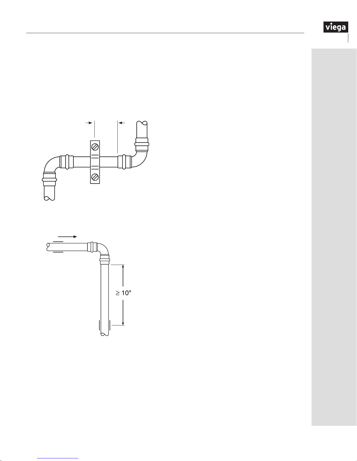
All parts of the support equipment need to be
designed and installed to not disengage due
to movement of the supported piping. Sliding
hangers must be positioned so that they cannot
unintentionally become rigid hangers when the
system is in use. See Figure 3.1. Figure 3.2 shows
a sliding pipe hanger that becomes a rigid hanger
with spacing in excess of 10".
Figure 3.1 Spacing for sliding pipe hanger
4"
Figure 3.2 Spacing for sliding pipe hanger
At no point in the piping system should a fitting
be the sole means of support. For example, when
installing a tee, both the branch and the trunk must
be properly supported. Piping systems should
be isolated from shock and vibration through the
proper use of hangers, supports and vibrationeliminating devices.
3.5.9 Pressure surges
The maximum operating pressure in a ProPress
system is 200 psi; this is a working limit and applies
to general operation as well as pressure transients.
Good engineering practices should be utilized to
design the system in a way that minimizes sharp
pressure surges. Pressure surges or transients from
fast acting valves, pump surges and other sources
that result in water hammer effects can cause
damage to many system components, including
press ttings. When fast acting valves and/or
pumps are incorporated into any system, the
designer and installer should isolate press ttings
from the effects of sharp pressure surges. ProPress
ttings should be isolated or separated by sufcient
distance from pumps, fast acting valves and other
sources of pressure transients.
3.6 Viega ProPress installation requirements
The following are special requirements to consider
when installing the Viega ProPress fitting system.
3.6.1 Rotating a pressed fitting
Once a Viega ProPress fitting has been pressed, it
can be rotated (not by hand), but once rotated more
than five degrees, the fitting must be re-pressed
to restore resistance to rotational movement. If the
fitting is re-pressed, care should be taken to align
the flats on the jaw and fitting.
3.6.2 Deflection
When pressing Viega ProPress fittings in a system,
the deformation of the fitting is constant. This
allows for a consistent leak-free joint every time
and is a result of the pressing technique.
The pressing process can cause deflection
(angular misalignment) to occur. Deflection
while pressing can be corrected by alternating
the position of the press tool on each fitting
connection. An example would be placing the
press tool on the right side of the first press
connection and alternating to the left side of the
press fitting on the second connection.
While deflection cannot be completely eliminated,
it can be minimized using this method.
3.7 Identification
All Viega ProPress piping systems should be
continuously marked in accordance with ANSI
A13.1 or as required by the local Authority
Having Jurisdiction.
IM-PP 724607 0815
19
Page 20

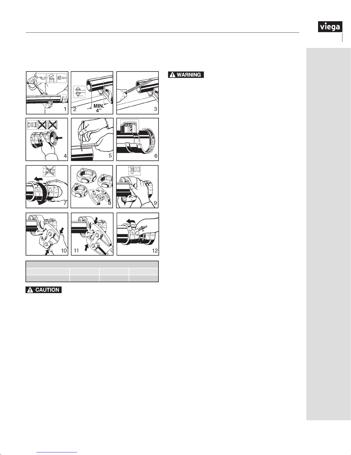
3.8 Viega ProPress ½" to 2" installation
For Types K, L and M Hard Copper Tubing in ½" to 2" and Soft Copper Tubing in ½" to 1¼".
1 2 3
4 5 6
7 8
Viega ProPress Insertion Depth Chart
Tube Size ½" ¾" 1" 1¼" 1½" 2"
Insertion Depth ¾" ⅞" ⅞" 1" 1
7
/16" 19/16"
for installing Viega ProPress fittings. Failure to follow all
Read and understand all instructions
instructions may result in extensive property damage,
serious injury or death.
1. Cut copper tubing at right angles using displacementtype cutter or ne-toothed steel saw.
2. Remove burr from inside and outside of tubing to
prevent cutting sealing element.
3. Check seal for correct t. Do not use oils or lubricants.
Use only Viega ProPress Shiny Black EPDM or Dull
Black FKM sealing elements.
Note: For applications requiring Viega ProPress with FKM
sealing elements, remove the factory-installed EPDM
sealing element and replace with FKM sealing element.
4. Mark proper insertion depth as indicated by the Viega
ProPress Insertion Depth Chart. Improper insertion
depth may result in improper seal.
5. While turning slightly, slide press tting onto tubing to
the marked depth.
Note: End of tubing must contact stop.
6. Insert appropriate Viega jaw into the pressing tool and
9
push in, holding pin until it locks in place.
7. Open the jaw and place at right angles on the tting.
Visually check insertion depth using mark on tubing.
8. Start pressing process and hold the trigger until the jaw
has engaged the tting.
9. After pressing, the jaw can be opened again.
Leak Testing with Smart Connect
®
:
Unpressed connections are located by
pressurizing the system with air or water.
When testing with water the proper
pressure range is 15 psi to 85 psi maximum.
Leak testing with air can be dangerous at
high pressures. When testing with compressed air the proper
pressure range is ½ psi to 45 psi maximum. Following a
successful leak test, the system may be pressure tested up
to 200 psi with air, or up to 600 psi with water, if required by
local code requirements or project specications.
20
IM-PP 724607 0815
Page 21

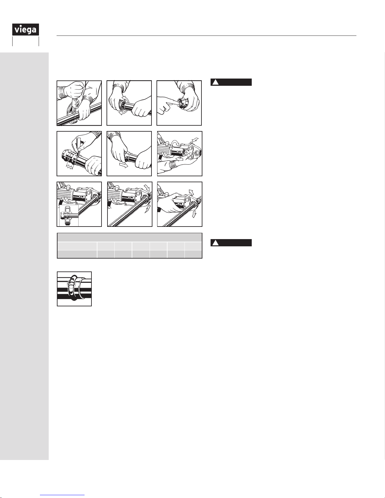
3.9 Viega ProPress XL (Copper) 2½" to 4" installation
For Types K, L and M Hard Copper Tubing in 2½" to 4"
1 2 3
4
7 8
10 11
ProPress XL (copper) Insertion Depth Chart
Tube Size
Insertion Depth 1⅝" 1⅞" 2⅜"
½"
2
5
9
12
3" 4"
instructions for installing ProPress XL (copper) fittings.
Failure to follow all instructions may result in extensive
property damage, serious injury or death.
1.
Cut copper tubing at right angles using displacement-type
cutter or ne-toothed steel saw.
2.
Keep end of tubing a minimum of 4" away from the
contact area of the vise to prevent possible damage to the
tubing in the press area.
3.
Remove burr from inside and outside of tubing to prevent
cutting sealing element.
4.
Check seal and grip ring for correct t. Do not use oils or
6
lubricants. Use only ProPress Shiny Black EPDM sealing
elements.
5.
Illustration demonstrates proper t of grip ring, separation
ring and sealing element.
6.
Mark proper insertion depth as indicated by the ProPress
XL (copper) Insertion Depth Chart. Improper insertion depth
may result in an improper seal.
7.
While turning slightly, slide press tting onto tubing to the
marked depth. End of tubing must contact stop.
8.
ProPress XL (copper) tting connections must be
performed with ProPress XL-C Rings and V2 ACTUATOR.
Use of ProPress XL Rings and/or Actuator (for Bronze
ttings) will result in an improper connection. See RIDGID
Operator’s Manual for proper tool instructions.
9.
Open XL-C Ring and place at right angles on the tting.
XL-C Ring must be engaged on the tting bead. Check
insertion depth.
10.
With V2 ACTUATOR inserted into the tool, open the V2
ACTUATOR as shown and connect V2 ACTUATOR to the
XL-C Ring.
11.
Place V2 ACTUATOR onto XL-C Ring and start pressing
process. Hold the trigger until the Actuator has engaged
the XL-C Ring. Keep extremities and foreign objects away
from XL-C Ring and V2 ACTUATOR during pressing
operation to prevent injury or incomplete press.
12.
Release V2 ACTUATOR from XL-C Ring and then remove
the XL-C Ring from the tting on completion of press.
Remove
performed.
Read, understand and follow all
tag from tting, indicating press has been
IM-PP 724607 0815
Leak Testing with Smart Connect®: Unpressed connections
are located by pressurizing the system with air or water.
When testing with water the proper pressure range is 15 psi
to 85 psi maximum. Leak testing with air can be dangerous
at high pressures. When testing with compressed air the
proper pressure range is ½ psi to 45 psi maximum. Following
a successful leak test, the system may be pressure tested up
to 200 psi with air, or up to 600 psi with water, if required by
local code requirements or project specications.
21
Page 22

3.10 Viega ProPress for Stainless ½" to 2" installation
CAUTION
For use only with Viega stainless steel tubing
1
4
Viega ProPress for Stainless Insertion Depth Chart
Pipe Size ½" ¾" 1" 1¼" 1½" 2"
Insertion Depth ¾"
5
7
7
/8"7/8" 1" 17/16" 19/16"
2
8
3
6
9
It is the responsibility of designers of piping
systems to verify the suitability of type 304 and 316 stainless
steel pipe for use with the intended uid media. The uid’s
chemical composition, pH level, operation temperature,
chloride level, oxygen level, and ow rate and their effect
on AISI type 316 stainless steel must be evaluated by the
material specier to conrm system life will be adequate
for the intended service. Failure to do so may cause
serious personal injury or property damage. Contact
Viega Technical Services for questions and approvals.
instructions for installing Viega ProPress for Stainless
Read, understand and follow all
fittings. Failure to follow all instructions may result in
extensive property damage, serious injury or death.
1. Cut stainless steel tubing only with an approved
stainless steel pipe cutting tool. Cut tubing at right
angle to permit proper joining with the fitting.
2. Remove burr from inside and outside of tubing to
prevent damage to the sealing element.
3. Check seal for correct t. Do not use oils or lubricants.
Use only Viega ProPress Shiny Black EPDM or Dull
Black FKM sealing elements.
4. Mark proper insertion depth as indicated by the Viega
ProPress Insertion Depth Chart. Improper insertion
depth may result in improper seal.
5. While turning slightly, slide press tting onto tubing to
the marked depth.
Note: End of tubing must contact stop.
6. Insert appropriate Viega jaw into the pressing tool and
push in, holding pin until it locks in place.
7. Open the jaw and place at right angles on the tting.
Visually check insertion depth using mark on tubing.
8. Start pressing process and hold the trigger until the
jaw has engaged the tting.
9. After pressing, the jaw can be opened again.
Leak Testing with Smart Connect®:
Unpressed connections are located by
pressurizing the system with air or water.
When testing with water the proper
pressure range is 15 psi to 85 psi maximum.
Leak testing with air can be dangerous at
high pressures. When testing with compressed air the proper
pressure range is ½ psi to 45 psi maximum. Following a
successful leak test, the system may be pressure tested up
to 200 psi with air, or up to 600 psi with water, if required by
local code requirements or project specications.
22
IM-PP 724607 0815
Page 23
3.11 Viega ProPress XL (Stainless) 2½" to 4" installation
For use only with Viega stainless steel tubing
Viega ProPress XL (Stainless) Insertion Depth Chart
Pipe Size 2½" 3" 4"
7
Insertion Depth 1⅝" 1
/8" 2⅜"
It is the responsibility of designers of
piping systems to verify the suitability of type 304 and 316
stainless steel pipe for use with the intended uid media.
The uid’s chemical composition, pH level, operation
temperature, chloride level, oxygen level, and ow rate
and their effect on AISI type 316 stainless steel must be
evaluated by the material specier to conrm system
life will be adequate for the intended service. Failure to
do so may cause serious personal injury or property
damage.
instructions for installing Viega ProPress for Stainless
Read, understand and follow all
fittings. Failure to
extensive property damage,
1.
Cut stainless steel tubing only with an approved
follow all instructions may result in
serious injury or death.
stainless steel pipe cutting tool. Cut tubing at right
angle to permit proper joining with the tting.
2. Keep end of tube a minimum of 4" away from the
contact area of the vise to prevent possible damage
to the tube in the press area.
3. Remove burrs from inside and outside of tubing to
prevent damage of the sealing element.
4. Check seal and grip ring for correct t. Do not
use oils or lubricants. Use only Viega ProPress XL
(Stainless) sealing elements.
5.
Mark proper insertion depth as indicated by Viega
ProPress XL (Stainless) insertion depth chart. Improper
insertion depth may result in an improper seal.
6. Illustration demonstrates proper t of grip ring,
separation ring and sealing element.
7. While turning slightly, slide press tting onto pipe to
the marked depth.
Note: End of tube must contact stop.
8. Press Viega ProPress XL (Stainless) tting connections
with Viega ProPress XL-C rings and V2 ACTUATOR.
Note: Use of Viega ProPress XL rings and/
or Actuator (for Bronze Fittings) will result in an
improper connection. See Ridge Tool operator’s
manual for proper tool instructions.
9. Open XL-C Ring and place at right angles on the
tting. XL-C
Ring must be engaged on the tting
bead. Check insertion depth.
10. With V2 ACTUATOR inserted in the tool, open
the V2 ACTUATOR as shown and connect the V2
ACTUATOR to the XL-C Ring.
11.
Place the V2 ACTUATOR onto the XL-C Ring. Hold
the trigger until the Actuator has engaged the XL-C
Ring. Keep extremities and foreign objects away from
the XL-C Ring and V2 ACTUATOR during pressing
operation to prevent injury or incomplete press.
12.
Release V2 ACTUATOR from XL-C Ring and then
remove the XL-C Ring from the tting on completion
of press. Remove tag from tting, indicating press
has been completed.
Leak Testing with Smart Connect®: Unpressed connections
are located by pressurizing the system with air or water.
When testing with water the proper pressure range is 15 psi
to 85 psi maximum. Leak testing with air can be dangerous
at high pressures. When testing with compressed air the
proper pressure range is ½ psi to 45 psi maximum. Following
a successful leak test, the system may be pressure tested up
to 200 psi with air, or up to 600 psi with water, if required by
local code requirements or project specications.
IM-PP 724607 0815
23
Page 24
3.12 Viega ProPressG
For Types K, L and M Hard Copper Tubing in ½" to 2" and Soft Copper Tubing in ½" to 1¼"
!
1 2 3
4 5 6
7 8
Viega ProPress Insertion Depth Chart
Tube Size ½" ¾" 1" 1¼" 1½" 2"
Insertion Depth ¾" ⅞" ⅞" 1" 1
Leak Testing with Smart Connect®:
Unpressed connections are located by
pressurizing the system with air or water.
Leak testing with air can be dangerous
at high pressures. When testing with
compressed air the proper pressure range
is ½ psi to 45 psi maximum. Following a successful
leak test, the system may be pressure tested up to 200
psi if required by local code requirements or project
specications.
7
/16" 19/16"
WARNING
for installing Viega ProPressG fittings for fuel gas.
Failure to follow all instructions may result in
significant property damage, serious injury or death.
1. Cut copper tubing at right angles using
displacement-type cutter or ne-toothed steel saw.
2. Remove burr from inside and outside of tubing to
prevent cutting sealing element.
3. Check seal for correct fit. Do not use oils or
lubricants. Use only Viega ProPress Yellow HNBR
sealing elements.
4. Mark proper insertion depth as indicated by the Viega
ProPress Insertion Depth Chart. Improper insertion
depth may result in improper seal.
5. While turning slightly, slide press tting onto tubing to
the marked depth.
Note: End of tubing must contact stop.
6. Insert appropriate Viega jaw into the pressing tool
and push in, holding pin until it locks in place.
7. Open the jaw and place at right angles on the tting.
Visually check insertion depth using mark on tubing.
8. Start pressing process and hold the trigger until the
9
jaw has engaged the tting.
9. After pressing, the jaw can be opened again.
!
WARNING
instructions should be followed when installing Viega
ProPressG fittings for Fuel Gas.
•Theinstallationshallbemadeinaccordancewithlocal
codes or, in the absence of local codes, in accordance with
the National Fuel Gas Code NFPA 54 or the LP-Gas Code
NFPA 58, as applicable.
For use with type K or L copper tubing, drawn copper from
•
½" to 2", and annealed copper from ½" to 1¼". All copper
must be in compliance with ASTM B-88.
•
The ttings are for use with fuel gases only and are intended for
operating pressure specied (maximum 125 psi).
•
Undue stress or strain on the ttings and the tubing is to be
avoided.
•
Concealed tubing and ttings shall be protected from puncture
threats.
•
If the installation requires components in addition to those
supplied by the tting manufacturer, those components
shall be specied. The instructions shall state that only the
components provided or specied by the manufacturer are
to be used in the installation.
•Thetting/tubingsystemshallnotbeusedasagrounding
electrode for an electrical system.
•Theinspection,testingandpurgingoftheinstallation
shall be performed using procedures specied in Part 4 of
the National Fuel Gas Code NFPA 54, ANSI Z223 or the
LP-Gas Code NFPA 58 section 3.2-10 as applicable, or in
accordance with the requirements of the applicable local
codes.
For use with natural, propane, mixed and manufactured
•
gases in the vapor state, not in the liquid state.
•Thetting/tubingsystemshallnotbeusedasameansof
support.
Read and understand all instructions
The following standards, codes and
24
IM-PP 724607 0815
Page 25

4 Warranty
4.1 Limited warranty for Viega ProPress fittings and valves
Subject to the conditions and limitations in this Limited Warranty, Viega LLC (Viega) warrants to
wholesalers and licensed plumbing and mechanical contractors in the United States and Canada that its
Viega ProPress fittings, when properly installed in non industrial and non marine applications and under
normal conditions of use, will be free of failure from manufacturing defect for a period of fifty (50) years
from date of installation and that its Viega ProPress valves, when properly installed in non industrial and
non marine applications and under normal conditions of use, will be free of failure from manufacturing
defect for a period of two (2) years from date of installation.
Under this Limited Warranty, you only have a right to a remedy if the failure or leak resulted from a
manufacturing defect in the products covered by this warranty and the failure or leak occurred during the
warranty period. You do not have a remedy under this warranty and the warranty does not apply if the
failure or any resulting damage is caused by (1) components other than those manufactured or sold by
Viega; (2) not designing, installing, inspecting, or testing the Viega ProPress fittings or valves in accordance
with Viega’s installation instructions in effect at the time of the installation; applicable code requirements;
and accepted industry practice; (3) improper handling and protection of the product prior to and during
installation, inadequate freeze protection, exposure to water pressures or temperatures or in applications
outside acceptable operating conditions; (4) acts of nature such as, but not limited to, earthquakes, fire,
flood, or lightning, or (5) external environmental causes, such as water quality variations, aggressive water,
or other external chemical or physical conditions.
In the event of a leak or other failure of the parts covered by this warranty, it is the responsibility of the
property owner to obtain and pay for repairs. Only if the warranty applies will Viega be responsible for the
remedy under this warranty. The part or parts which you claim failed should be kept and Viega contacted
by writing to the address below or telephoning 1-800-976-9819 within thirty (30) days after the leak or
other failure and identifying yourself as having a warranty claim. You should be prepared to ship, at your
expense, the product which you claim failed due to a manufacturing defect and document the date of
installation. Within a reasonable time after receiving the product, Viega will investigate the reasons for the
failure, which includes the right to inspect the product at Viega. Viega will notify you in writing of the results
of its review.
In the event that Viega determines that the failure or leak was the result of a manufacturing defect in the
part covered by this warranty and that this warranty applies, the EXCLUSIVE AND ONLY REMEDY under
this warranty shall be the reimbursement for repair and/or replacement of the part. VIEGA SHALL NOT BE
LIABLE FOR ANY CONSEQUENTIAL OR OTHER DAMAGE (FOR EXAMPLE, WATER OR PROPERTY OR
MOLD REMEDIATION) UNDER ANY LEGAL THEORY AND WHETHER ASSERTED BY DIRECT ACTION,
FOR CONTRIBUTION OR INDEMNITY OR OTHERWISE.
THE ABOVE WARRANTY IS IN LIEU OF ALL OTHER WARRANTIES, EXPRESS OR IMPLIED, INCLUDING
BUT NOT LIMITED TO THE IMPLIED WARRANTIES OF MERCHANTABILITY AND FITNESS FOR A
PARTICULAR PURPOSE. If a limited warranty shall be found to apply, such warranty is limited to four
years. Other than this Limited Warranty, Viega does not authorize any person or firm to create for it any
other obligation or liability in connection with its products.
This Limited Warranty gives you specific legal rights and you also may have other rights which may vary
from state to state. This warranty shall be interpreted and applied under the law of the state in which the
product is installed and is intended as a Commercial Warranty.
IM-PP 724607 0815
25
Page 26

4.2 Limited warranty for marine and industrial applications
Subject to the terms and conditions of this Limited Warranty, Viega LLC (Viega) warrants to end users,
installers and distribution houses that its Viega metal press products (Viega product) when properly
installed in industrial and marine applications shall be free from failure caused by manufacturing defects
for a period of two (2) years from date of installation. For purposes of this warranty, industrial applications
are defined as non residential and non commercial applications not normally accessible to the general
public. Marine applications are defined as mobile structures used to navigate water or stationary structures
in water.
Under this Limited Warranty, you only have a right to a remedy if the failure or leak resulted from a
manufacturing defect in the Viega product and the failure or leak occurs during the warranty period. You
do not have a remedy under this warranty and the warranty remedy does not apply if the failure or any
resulting damage is caused by (1) components other than those sold by Viega; (2) not designing, installing,
inspecting, testing, or maintaining the Viega product in accordance with Viega’s installation and product
instructions in effect at the time of installation and other specifications and approvals applicable to the
installation; (3) improper handling and protection of the Viega product prior to, during and after installation,
inadequate freeze protection, or exposure to environmental or operating conditions not recommended
for the application; or (4) acts of nature, such as, but not limited to earthquakes, fire, or weather damage.
Final approval as to use compatibility to a specific process or fluid application is the responsibility of the
engineer of record or responsible design/facilities personnel and this Limited Warranty only applies to
manufacturing defects in the Viega Product.
In the event of a leak or other failure in the Viega product covered by this warranty, it is the responsibility of
the end user to take appropriate measures to diminish any damage, to include making timely repairs. Only
if the warranty applies will Viega be responsible for the remedy under this warranty. The part or parts which
you claim failed should be kept and Viega contacted by writing to the address below or telephoning
1-800-976-9819 within thirty (30) calendar days after the leak or other failure and identifying yourself as
having a warranty claim. You should be prepared to ship, at your expense, the product which you claim
failed due to a manufacturing defect, document the date of installation, and the amount of the repair
or replacement if performed by you. Within a reasonable time after receiving the product, Viega will
investigate the reasons for the failure, which includes the right to inspect the product at a Viega location
and reasonable access to the site of damage. Viega will notify you in writing as to the results of its review.
In the event that Viega determines that the failure or leak was the result of a manufacturing defect in
the Viega Product covered by this warranty and to which this warranty applies, the EXCLUSIVE AND
ONLY REMEDY under this warranty shall be the reimbursement for reasonable charges for repair
or replacement of the Viega Product itself. VIEGA SHALL NOT BE LIABLE FOR CONSEQUENTIAL
OR OTHER DAMAGE (FOR EXAMPLE, ECONOMIC LOSS, WATER OR PROPERTY OR MOLD
REMEDIATION) UNDER ANY LEGAL THEORY AND WHETHER ASSERTED BY DIRECT ACTION, FOR
CONTRIBUTION OR INDEMNITY OR OTHERWISE.
THE ABOVE WARRANTY IS IN LIEU OF ALL OTHER WARRANTIES, EXPRESS OR IMPLIED, INCLUDING,
BUT NOT LIMITED TO, THE IMPLIED WARRANTIES OR ANY STATUTE OF LIMITATIONS RELATING TO
SUCH WARRANTIES. Other than this Limited Warranty, Viega does not authorize any person or firm to
create for it any other obligation or liability in connection with its products.
This Limited Warranty gives you specific legal rights and you also may have other rights which may vary
from state to state. This warranty shall be interpreted and applied under the law of the state in which the
product is installed and is intended as a Commercial Warranty.
26
IM-PP 724607 0815
Page 27

Notes
IM-PP 724607 0815
27
Page 28

This document subject to updates. For the most current Viega technical literature please visit www.viega.us.
Click Services -> Click Electronic Literature Downloads -> Select Product Line -> Select Desired Document
*Zero Lead identies Viega
®
products meeting the lead free requirements of NSF 61-G through testing under
NSF/ANSI 372 (0.25% or less maximum weighted average lead content).
Viega LLC
100 N. Broadway, 6th Floor
Wichita, KS 67202
Phone: 1-800-976-9819
www.viega.us
©2015, Viega®, ProPress®, MegaPress®, SeaPress®, ProGeo® and FostaPEX®, are
registered trademarks of Viega GmbH & Co. KG. Smart Connect
Radiant Wizard
of Viega GmbH & Co. KG. MiniBloc™, ProRadiant™, Zero Lead™, PolyAlloy™,
SmartLoop™, are trademarks of Viega LLC. RIDGID
RIDGID, Inc. LoopCAD
®
are registered trademarks of Viega LLC. ViegaPEX™, is a trademark
®
®
is a registered trademark of Avenir Software Inc.
is a registered trademark of
®
, ManaBloc® and
IM-PP 724607 0815
 Loading...