

Page 1
Viega Eco Plus WC element
Instructions for Use
Viega Eco Plus
Model Year built:
8130.2 from 03/2014
en_INT
Page 2

Viega Eco Plus WC element 2 from 23
Page 3
Table of contents
1 About these instructions for use 4
Table of contents
1.1
1.2
1.3
Target groups 4
Labelling of notes 4
About this translated version 5
2 Product information 6
2.1
2.2
2.2.1
2.3
2.3.1
2.3.2
2.3.3
2.3.4
Standards and regulations 6
Intended use 6
Areas of use 6
Product description 6
Overview 6
Compatible components 7
Sound protection 9
Technical data 9
3 Handling 10
3.1
3.1.1
3.1.2
3.1.3
3.2
3.2.1
3.2.2
3.2.3
3.2.4
3.3
3.4
Assembly information 10
Mounting conditions 10
Installation dimensions 11
Required tools 11
Assembly 11
Mounting WC element 11
Converting actuation 18
Preparing optional actuation versions 21
Setting the flush volume 22
Cleaning and maintenance 22
Disposal 23
Viega Eco Plus WC element 3 from 23
Page 4
About these instructions for use
1 About these instructions for use
Trade mark rights exist for this document; for further information, go to
viega.com/legal.
1.1 Target groups
The information in this instruction manual is directed at the following
groups of people:
n Heating and sanitary professionals and trained personnel
n Drywall builder
Individuals without the abovementioned training or qualification are not
permitted to mount, install and, if required, maintain this product. This
restriction does not extend to possible operating instructions.
1.2
The installation of Viega products must take place in accordance with
the general rules of engineering and the Viega instructions for use.
Labelling of notes
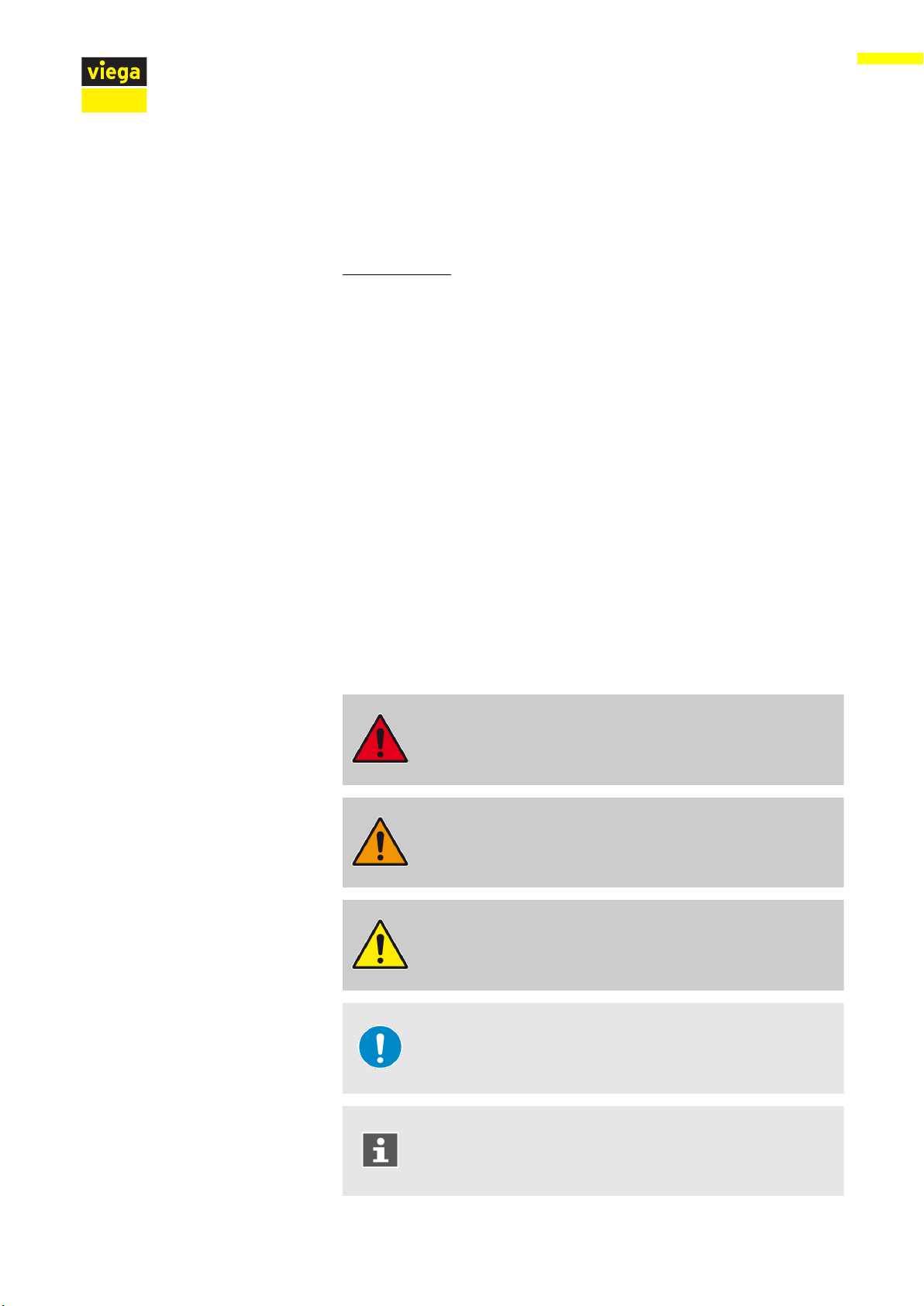
Warning and advisory texts are set aside from the remainder of the text
and are labelled with the relevant pictographs.
DANGER!
This symbol warns of possible life-threatening injury.
WARNING!
This symbol warns of possible serious injury.
CAUTION!
This symbol warns of possible injury.
NOTICE!
This symbol warns of possible damage to property.
This symbol gives additional information and hints.
Viega Eco Plus WC element 4 from 23
Page 5

1.3 About this translated version
This instruction for use contains important information about the choice
of product or system, assembly and commissioning as well as intended
use and, if required, maintenance measures. The information about the
products, their properties and application technology are based on the
current standards in Europe (e. g. EN) and/or in Germany
(e. g. DIN/DVGW).
Some passages in the text may refer to technical codes in Europe/
Germany. These should serve as recommendations in the absence of
corresponding national regulations. The relevant national laws, stand‐
ards, regulations, directives and other technical provisions take priority
over the German/European directives specified in this manual: The
information herein is not binding for other countries and regions; as said
above, they should be understood as a recommendation.
About these instructions for use
Viega Eco Plus WC element 5 from 23
Page 6

2 Product information
2.1 Standards and regulations
The following standards and regulations apply to Germany / Europe.
National regulations can be found on the relevant web site of your
country at viega.com/standards.
Regulations from section: Fields of application / Mounting conditions
Scope / Notice Regulations applicable in Ger‐
suitable masonry walls EN 1996-1-1
suitable concreted walls DIN 1045
Product information
many
2.2 Intended use
2.2.1 Areas of use
suitable support profiles DIN 18183
Regulations from section: Sound protection
Scope / Notice Regulations applicable in Ger‐
many
Fulfilled noise protection require‐
ments
Fulfilled noise protection require‐
ments
Fulfilled noise protection require‐
ments
The Viega Eco Plus WC element is suitable for mounting on masonry
wall constructions and support profiles pursuant to the regulations in
section Ä „Regulations from section: Fields of application / Mounting
conditions“ on page 6.
DIN 4109
DIN 4109 (additional sheet 2)
VDI 4100 SSt I-SSt II
2.3
Product description
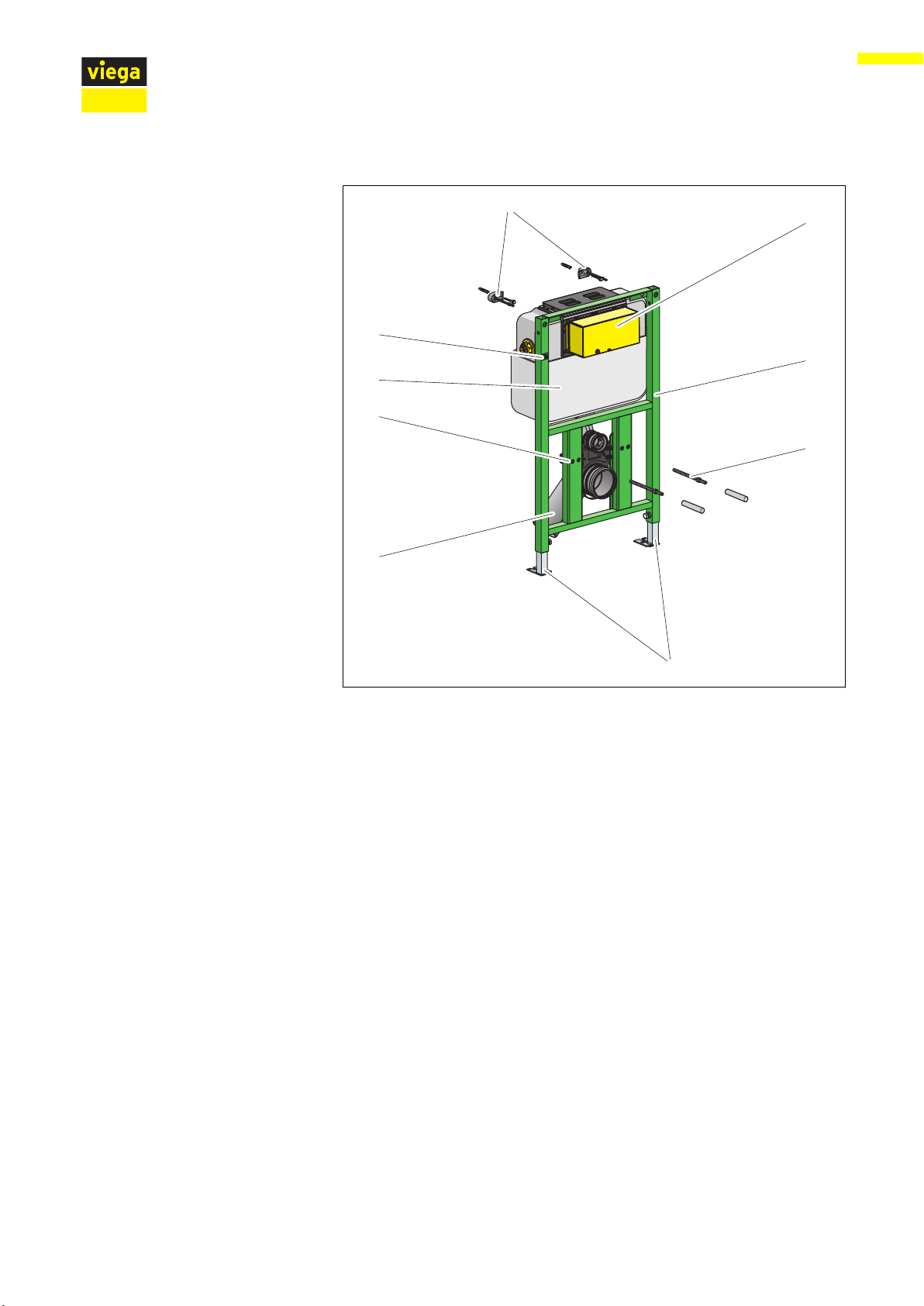
2.3.1 Overview
The WC element is equipped as follows:
Viega Eco Plus WC element 6 from 23
Page 7
2
1
9
8
3
5
6
7
4
Product information
Fig. 1: Components
1 - Viega Eco Plus WC element
2 - threaded rods for fixing sanitary objects
(gauges for bore hole 180 or 230 mm)
3 - adjustable feet
4 - drain elbow
5 - fixing height for the WC ceramic: 330 mm
6 - Viega concealed cistern 2L
7 - marking 0.7 m above the upper edge of the finished floor
8 - fixing set (not included in the scope of delivery model 8173)
9 - flush actuation site protection
2.3.2 Compatible components
The WC element is compatible with all common WC ceramics, even
with larger projection (barrier-free).
The WC element can be extended by the following compatible compo‐
nents:
n fixing set (model 8173)
n connection installation set (model 8350.14)
Installation of the WC element into the modular Viegaswift pre-wall
installation system (model 8110.5) is possible.
Viega Eco Plus WC element 7 from 23
Page 8

Connection installation set
Compatible flush plates
Product information
Mount the components in accordance with the respective instructions
for use.
The installation set is suitable for the connection of an electrical actua‐
tion. The installation set consists of an empty pipe, a cavity wall socket
and the relative, required clip. The empty pipe connects the cavity wall
socket with the concealed cistern.
Product Name Model
Standard Flush plate Standard 1 8180.1
Visign for Style Flush plate
Visign for Style 10
Flush plate
Visign for Style 11
Flush plate
Visign for Style 12
Flush plate
Visign for Style 12
Flush plate
Visign for Style 13
Flush plate
Visign for Style 14
Functional unit 8332.3
Visign for More Flush plate Visign for More
100
Flush plate Visign for More
101
Flush plate Visign for More
102
8315.1
8331.1
8332.1
8332.4
8333.1
8334.1
8352.1
8351.1
8353.1
Flush plate Visign for More
8355.1
103
Flush plate Visign for More
8354.1
104
Visign for Care
sensitive
Visign for More
sensitive
Flush plate sensitive Visign
for Care
Flush plate sensitive
Visign for More 100
Flush plate sensitive
8352.21
230 V 8352.11
6.5 V 8352.12
Visign for More 100
Viega Eco Plus WC element 8 from 23
Page 9

Product Name Model
Product information
2.3.3 Sound protection
Flush plate sensitive
Visign for More 103
Flush plate sensitive
Visign for More 103
Visign for Public Flush plate
Visign for Public 1
Flush plate
Visign for Public 2
Remote actuation
Visign for Public 1
Cover plate Visign for Public 8326.9
The WC element complies with the noise insulation requirements speci‐
fied in section Ä „Regulations from section: Sound protection“
on page 6.
230 V 8355.11
6.5 V 8355.12
8326.1
8327.1
8326.21
2.3.4
Flush volume
Technical data
Small flush volume Factory setting approx. 3 l
Setting range approx. 3–4 l
Large flush volume Factory setting approx. ca. 6 l
Setting range approx. 6–9 l
Viega Eco Plus WC element 9 from 23
Page 10

3 Handling
3.1 Assembly information
3.1.1 Mounting conditions
Suitable walls
The Viega WC element is suitable for mounting on masonry wall con‐
structions and support profiles pursuant to the regulations in section
Ä
tions“ on page 6.
The WC element may only be mounted on even wall surfaces.
Construction height
With the construction height, the marked height of the upper edge of
the finished floor must be observed.
Handling
„Regulations from section: Fields of application / Mounting condi‐
Installation depth
WC ceramic
Actuation
The installation depth can be between 85 mm and 200 mm.
The WC element can only be used in combination with wall-hung WCs
(fixing gauges for bore hole 180 mm or 230 mm).
The WC element can be extended by a remote actuation
Visign for Public1 (model 8326.21) or by an electronic actuation (model
8350.31 or 8350.32). The corresponding actuation method must be pre‐
pared before the WC element is clad and tiled.
The corresponding empty pipe (included in the scope of delivery of the
remote actuation) is required when preparing the remote actuation
Visign for Public1.
Viega Eco Plus WC element 10 from 23
Page 11

3.1.2 Installation dimensions
Dimensions
Handling
3.1.3 Required tools
3.2 Assembly
3.2.1 Mounting WC element
n drill with 10 mm drill bit
n ratchet with sockets: 13 mm / 17 mm
n fork or ring spanner: 10 mm / 13 mm / 17 mm / 19 mm
Masonry and concreted walls
You should use a support bracket (model 8165) when
mounting multiple WC elements with an interval of
> 490 mm. Observe the instructions for use of the support
bracket when mounting.
Viega Eco Plus WC element 11 from 23
Page 12

Masonry wall
X3
0-200
X1
X2
0
0-200
0
700
Ø10
560638_B2
13
1
7
Handling
Determine and mark fixing points.
n X1: 390 mm (model 8180.73)
n X2: 440 mm (model 8173)
n X3: 810 mm.
Drill holes.
Mount the fixing set with the fork spanner (size 13).
Align the height (size 17) of the WC element in accordance with the
height marking.
Mark fixing points on the floor.
Viega Eco Plus WC element 12 from 23
Page 13

Drill holes for fixing on the floor.
Ø10
13
17
180
230
click
1
9
Handling
Attach WC element to the floor using the fork spanner (size 13) and
the screws and dowels supplied.
Set the installation depth of the pre-wall element (200 mm) with the
fork spanner (size 17).
Mount WC threaded rods (gauges for bore hole 180 or 230 mm).
Clip in drain elbow.
Viega Eco Plus WC element 13 from 23
Page 14

Install site protection of the flush actuation.
2x
Attach protective caps for threaded rods onto WC ceramic.
Mount protective plug.
Handling
Carry out water connection.
Double clad WC element with IFGP cladding panels (model 8055.10)
(2 x 12.5 mm).
Viega Eco Plus WC element 14 from 23
Page 15

On-site support profile
75
90°
50
17
0-200
0
700
Handling
If necessary, adjust (pre-mounted) foot depth from 75 mm to
50 mm.
Pull the foot out and turn by 90°.
Determine construction height in accordance with the on-site
marking of the upper edge of the finished floor.
Pull WC element up (height marking) and align.
Tighten feet with the fork spanner (size 17).
Mark holes for floor supports.
Viega Eco Plus WC element 15 from 23
Page 16

Drill holes.
Ø10
1
3
4x
Handling
Attach element to floor (size 13).
Attach WC element to the support profiles using the screws sup‐
plied.
Connect the WC element flush with the support profiles.
Viega Eco Plus WC element 16 from 23
Page 17

click
180
230
19
Handling
Mount WC threaded rods (gauges for bore hole 180 or 230 mm).
Clip in drain elbow.
Install site protection of the flush actuation.
Attach protective caps for threaded rods onto WC ceramic.
Mount protective plug.
If necessary, mount a reducer.
Carry out water connection.
Viega Eco Plus WC element 17 from 23
Page 18

Strap the support profiles with panel strips ≥ 30 cm.
≥ 30
2x
Handling
3.2.2 Converting actuation
Double-clad WC element with IFGP cladding panels (model
8055.10) (2 x 12.5 mm).
Actuation can take place optionally from the front or the top. The actua‐
tion is pre-mounted from the front in delivery condition. To convert
actuation from above, proceed as follows:
Remove lateral cistern cover.
Viega Eco Plus WC element 18 from 23
Page 19

Handling
Press the bow backwards from the mounting of the mechanism.
Turn the mechanism's lock by 90° in an anti-clockwise direction.
The mechanism is unlocked and can be removed.
ð
Remove mechanism.
Remove upper revision cover.
Viega Eco Plus WC element 19 from 23
Page 20

Handling
Insert the mechanism into the cistern from above.
In doing so, ensure that the tracks on the top and bottom edge of
the mechanism are in the indentations in the revision shaft of the
cistern.
Turn the mechanism's lock by 90° in a clockwise direction.
The mechanism is locked.
ð
Hang the mechanism in the bow of the drain valve.
Insert cistern cover from above.
Viega Eco Plus WC element 20 from 23
Page 21

Insert revision cover from the front.
X
X
X1
X2
X3
Place revision shaft.
Double-clad (2 x 12.5 mm) and tile WC element with IFGP cladding
panels (model 8055.10).
3.2.3 Preparing optional actuation versions
Prepare remote actuation
Handling
Prepare electrical actuation
The corresponding empty pipe (included in the scope of delivery of the
remote actuation) is required when preparing the remote actuation
Visign for Public1 (model 8326.21).
Lead the empty pipe from the hollow wall socket into the concealed
cistern.
Distance from the remote actuation to the cistern (x)
n min. 1.0 m
n max. 1.7 m
A corresponding empty pipe (not included in the scope of delivery of the
electrical actuation) is required for the preparation of the electrical
actuation (model 8350.31 or model 8350.32).
Lead empty pipe from the switch or button into the concealed cis‐
tern, to connect the concealed socket and concealed cistern.
Positioning of the cistern power pack
n X1= max. 0.75 m
n X2= max. 2.75 m with an extension cable, 1 x article number 628 505
n X3= max. 4.75 m with two extension cables, 2 x article number 628
Viega Eco Plus WC element 21 from 23
505
Page 22

3.2.4 Setting the flush volume
Small flush volume
The WC element is factory-set at a small flush of approx. 3 l. The small
flush volume can be set at three levels: approx. 3 l / 3.5 l / 4 l.
Handling
Immediate re-flushing of the flush volume is possible at the
factory settings.
Remove the drain valve from the concealed cistern.
Push the slide control on the side of the overflow pipe to the desired
small flush volume:
n Top position: approx. 3 l
n Middle position: approx. 3.5 l
n Bottom position: approx. 4 l
Large flush volume
The positions can be identified by the notches.
The WC element is factory-set at a large flush volume of approx. 6 l. The
large flush volume can be set continuously from approx. 6 l up to
approx. 9 l.
Remove the drain valve from the concealed cistern.
Push the slide control below the drain valve to the desired large
flush volume:
n left: approx. 6 l
n right: approx. 9 l
3.3 Cleaning and maintenance
Cleaning may only be carried out by specialist trade professionals or
qualified experts.
Viega Eco Plus WC element 22 from 23
Page 23

Cleaning and maintenance of the concealed cistern
The concealed cistern is constantly under mechanical, chemical, and
physical stress. For this reason, the components must be cleaned as
required, and the drain and filling valve seals renewed.
In areas or regions with hard water due to high concentration of calcium
or magnesium salts, there is the risk of limescale deposits developing
on the inlet and drain valves. The valves may have to be replaced,
depending on the extent of the deposits.
Depending on the position of the flush plate, work on the
concealed cistern can be carried out from the front or from
above through the revision opening.
Handling
3.4 Disposal
Separate the product and packaging materials (e. g. paper, metal,
plastic or non-ferrous metals) and dispose of in accordance with valid
national legal requirements.
Viega Eco Plus WC element 23 from 23
 Loading...