

Page 1
1
VGA1279AU.170403 • www.viega.com.au
Installation Guide for Viega Eco Plus 1F
Concealed Cistern for Wall Mount Pan
Cistern Model 8108.10
A
C
G
D
H
E
F
I
J
B
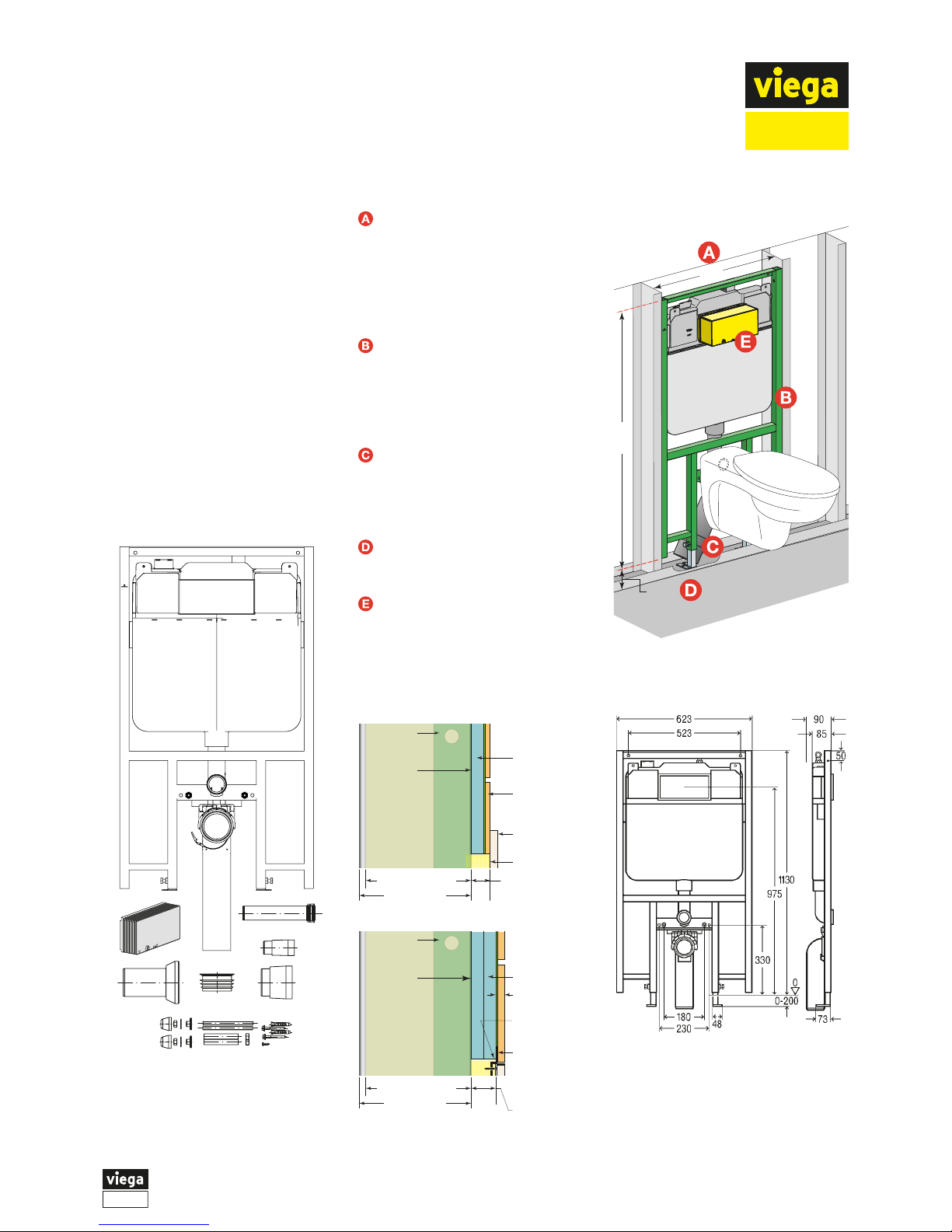
Components
A Viega Eco Plus 1F assembly.
B Cistern access duct.
C Flushing pipe with bend.
D Flushing pipe – (horizontal adaptor).
E Dust cover for flushing pipe.
F Sewer outlet pipe (90x400mm).
G Pan adaptor pipe
H Dust cover for sewer outlet pipe.
I 90 to 100mm sewer adaptor ring.
J Floor mounting hardware and pan
mounting hardware.
Optional hardware not shown here.
Mounting hardware for face fixing
to masonry. Fixing set 8173 or
8180.73.
623
1130
0-200
Pan not
included
Notes on Eco Plus 1F Installation
Cistern may be installed in stud
framing or face mounted to
masonry. Minimum spacing of
623mm between studs. Studs
must be able to support the
applied loads. Refer to project
engineer/details.
The waste outlet pipe is 90mm
OD, therefore in 90mm cavity
installations, accurate alignment
of the front face of the mounting
bracket with the front face of the
studs is critical.
Where the waste pipe is to
penetrate a concrete slab floor, it
is suggested that core drilling be
carried out where a high degree of
alignment accuracy is required.
Allow for screed and tile thickness
where applicable in all height
calculations.
For the correct mounting of
flushing plates, the total thickness
of wall linings (i.e. total of lining +
tiles + adhesive) must be within
a specified range. Refer to the
following details.
90mm min.
framing
85mm cistern
17-100mm
cistern face
to tile face
Face Mount
Flushing Plate
Tiles + Glue
Cistern
tank
Duct to tile face
Wall Lining
90mm min.
framing
85mm cistern
Cistern
tank
Tiles + Glue
5-18mm
Wall Lining
25-100mm wall
lining thickness
Recessed
Mounting Plate
fixed to wall
lining face
before tiling
Face Mount
Flushing Plate
Recessed
Mount
Flushing Plate
Duct to wall
lining face
Cistern
Mounting
Bracket
aligned
with face
of frame
Cistern
Mounting
Bracket
Cistern
Mounting
Bracket
aligned
with face
of frame
Cistern
Mounting
Bracket
Page 2
2
VGA1279AU.170403 • www.viega.com.au
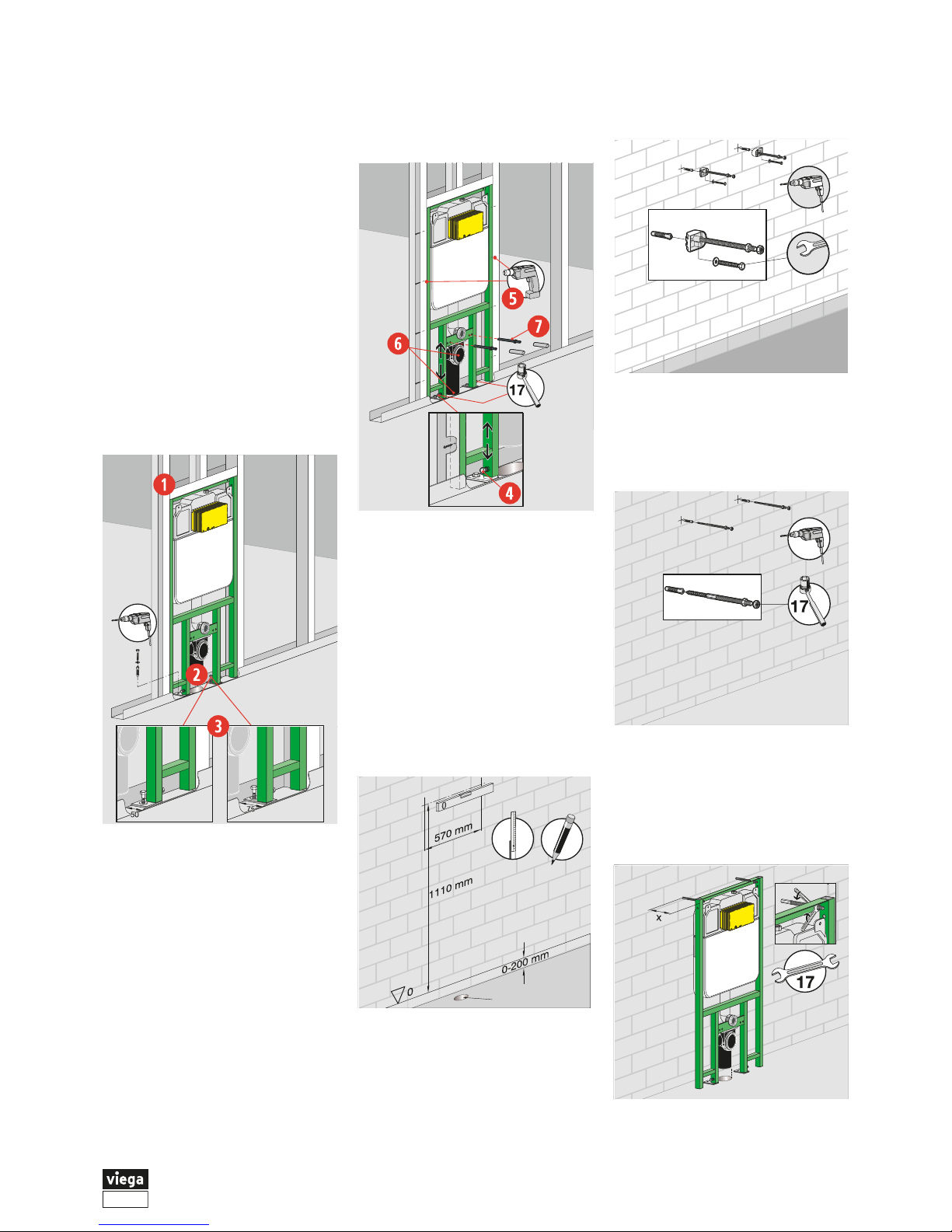
Cistern Installation in Stud Wall
For installation to a masonry wall,
proceed to Step 8.
Prepare studs to accept the cistern
and pan support bracket.
Minimum of 623mm between stud
fixing faces.
Ensure mains waste pipe is
appropriately located in floor, ready
to receive the waste connection.
Place the cistern bracket on the
feet and place the unit into the wall
space. Align the front face of the
cistern support bracket with the
face of the studs. Refer to previous
Notes. Position and fix the
mounting feet to the floor with
appropriate fixings. The feet may
be rotated to adjust for available
space.
Determine the appropriate height
for the pan (allow for screed and
floor tiling). Adjust the cistern/pan
bracket and fix the bracket to the
floor support posts with the built-in
clamping bolts.
Align the front face of the cistern
bracket with the face of the studs
and fix the bracket to the studs
with appropriate fasteners.
Trim waste outlet pipe to length
required. Mount the pipe in the
support bracket and secure with
the retaining clamp. A 90 to
100mm adaptor (Component I) is
supplied for the junction with the
main sewer line.
Determine the mounting centres
for the pan and fix mounting bolts
in place.
Proceed to Step 16.
Cistern Installation to Face of
Masonry Wall
Determine where the mains waste
pipe is or will be located in floor to
receive the waste connection.
Determine and mark the fixing
points for the cistern/pan support
bracket. Take into account the
desired pan mounting height, and
allow for floor screed and tiles.
Waste outlet pipe
Choose from Step 9 or Step 10.
Drill holes in masonry and install
the fixing brackets. Fit threaded
studs to brackets. (Use optional
fixing set 8173).
560638_B2
13
Proceed to Step 11.
Alternatively, drill holes in masonry
and install the fixing studs. (Use
optional fixing set 8180.73).
Place the cistern bracket on the
feet and place the unit onto the top
fixing studs with backing nuts
installed. Position the frame at the
required distance (85-200mm)
from the wall, install retaining nuts.
Page 3

3
VGA1279AU.170403 • www.viega.com.au
Check the frame line and level and
tighten the retaining nuts.
Position and fix the mounting feet
to the floor with appropriate fixings.
The feet may be rotated to adjust
for available space.
Fix the bracket to the floor support
posts with the built-in clamping bolts.
Determine the mounting centres
for the pan and fix mounting studs
in place.
Trim waste outlet pipe to length
required. Mount the pipe in the
support bracket and secure with
the retaining clamp. A 90 to
100mm adaptor (Component I) is
supplied for the junction with the
main sewer line.
Water Connection
To gain access to the cistern tap
remove the access duct (if fitted)
and keep for reinstallation.
Remove the internal guide plate
and keep for reinstallation.
Unlock the mechanism retainer.
Push the top of the mechanism
down, lean the mechanism
forward, then reach behind and
unhook the pull bar from the drain
valve stem.
Remove the mechanism from
the cistern.
90°
➊
➋
➌
Where the water inlet line/fitting
cannot be rotated to join into the
tank fitting, unscrew the inlet tap
from the through-tank fitting.
Connect the inlet water line to the
tank fitting (½" BSP female fitting).
The tank fitting can be rotated with
a spanner.
Refit the cistern tap and tighten
with a spanner. Turn tap to off
position ready for mains pressure
testing.
Where the incoming fitting can be
rotated, such as in a new
installation with a Propress Line
Adaptor Nº3, insert the thread into
the tank fitting and tighten with
spanners.
Connect incoming water line to
your chosen fitting.
Check that the inlet tap nut is tight.
Turn tap to off position ready for
mains pressure testing.
27
28
Page 4

4
VGA1279AU.170403 • www.viega.com.au
Reinstall the mechanism, internal
guide plate, and fit the access duct
(required for all installations).
Cover pan mounting bolts and
insert dust covers provided into the
flushing pipe and waste pipe to
protect during wall lining and tiling.
Store remaining components for
use during pan installation.
The unit may be encased to
project specifications.
Pan Installation
Proceed with the pan connection after
wall and floor tiling is completed. Refer
to pan manufacturer for installation
instructions.
Determine the required length for the
horizontal flushing pipe. Cut the plain
end to length if required. Assemble
the pan seal onto the plain end of the
horizontal pipe. Install the horizontal
flushing pipe into the seal of the
vertical flushing pipe.
Insert the pan seal into the back of
the pan and fix the pan in place.
Also refer to instructions supplied
with the adaptor pipe.
Mains Power Electrical Installation
Where mains power connection is
required, this must be installed by a
licensed electrician prior to wall lining/
tiling. Refer to Viega document
VGA1230AU.
Flushing Volume Adjustment
Flush volume settings are factory
set and should not need adjustment.
To carry out adjustment of the flushing
volumes, remove the flushing valve
from the cistern. Follow the instructions
for removing the flushing valve, refer to
Viega document VGA1188AU
Servicing Guide for Viega 1F
Concealed Cistern.
The factory settings for the small
flush is 3.0 l. The volume may be
adjusted between 2.5 l and 3.0 l
by moving the slider on the side of
the overflow pipe. The upper
position is 2.5 l. The lower position
is 3.0 l. The positions can be
identified by the notches.
The factory settings for the large
flush is 4.5 l. The volume is
infinitely adustable between 4.5 l
and 6.0 l by moving the slider
under the flushing valve housing.
The left position as shown in the
diagram is 4.5 l. The right position
as shown in the diagram is 6.0 l.
 Loading...