

Page 1
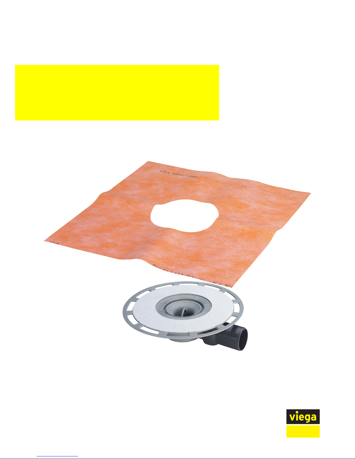
for bonded sealing (tiled shower) with sealing mat
Model Year built:
4938 from 01/2006
en_INT
Advantix bath drain
Instructions for Use
Page 2

Advantix bath drain 2 from 21
Page 3

Table of contents
1 About these instructions for use 4
1.1
Target groups 4
1.2
Labelling of notes 4
1.3
About this translated version 5
2 Product information 6
2.1
Standards and regulations 6
2.2
Intended use 6
2.2.1
Areas of use 6
2.2.2
Media 7
2.2.3
Drainage capacity 7
2.3
Product description 8
2.3.1
Overview 8
2.3.2
Technical data 8
2.4
Information for use 8
2.4.1
Installation variations 8
2.4.2
Sealing 10
2.4.3
Fire protection 12
2.5
Required accessories 12
3 Handling 14
3.1
Assembly information 14
3.1.1
Important note 14
3.1.2
Installation dimensions 15
3.1.3
Tools and materials 15
3.2
Assembly 15
3.2.1
Connecting the drain 15
3.2.2
Preparing for subsequent work 17
3.2.3
Sealing the drain 18
3.2.4
Mounting the top 19
3.3
Care 20
3.3.1
Care tips 20
3.3.2
Cleaning the drain 20
3.4
Disposal 21
Table of contents
Advantix bath drain 3 from 21
Page 4
1 About these instructions for use
Trade mark rights exist for this document; for further information, go to
viega.com/legal.
1.1 Target groups
The information in this instruction manual is directed at the following
groups of people:
n Heating and sanitary professionals and trained personnel
n Tilers
n Consumers
Individuals without the abovementioned training or qualification are not
permitted to mount, install and, if required, maintain this product. This
restriction does not extend to possible operating instructions.
The installation of Viega products must take place in accordance with
the general rules of engineering and the Viega instructions for use.
1.2
Labelling of notes
Warning and advisory texts are set aside from the remainder of the text
and are labelled with the relevant pictographs.
DANGER!
This symbol warns of possible life-threatening injury.
WARNING!
This symbol warns of possible serious injury.
CAUTION!
This symbol warns of possible injury.
NOTICE!
This symbol warns of possible damage to property.
This symbol gives additional information and hints.
About these instructions for use
Advantix bath drain 4 from 21
Page 5

1.3 About this translated version
This instruction for use contains important information about the choice
of product or system, assembly and commissioning as well as intended
use and, if required, maintenance measures. The information about the
products, their properties and application technology are based on the
current standards in Europe (e. g. EN) and/or in Germany
(e. g. DIN/DVGW).
Some passages in the text may refer to technical codes in Europe/
Germany. These should serve as recommendations in the absence of
corresponding national regulations. The relevant national laws, stand‐
ards, regulations, directives and other technical provisions take priority
over the German/European directives specified in this manual: The
information herein is not binding for other countries and regions; as said
above, they should be understood as a recommendation.
About these instructions for use
Advantix bath drain 5 from 21
Page 6
2 Product information
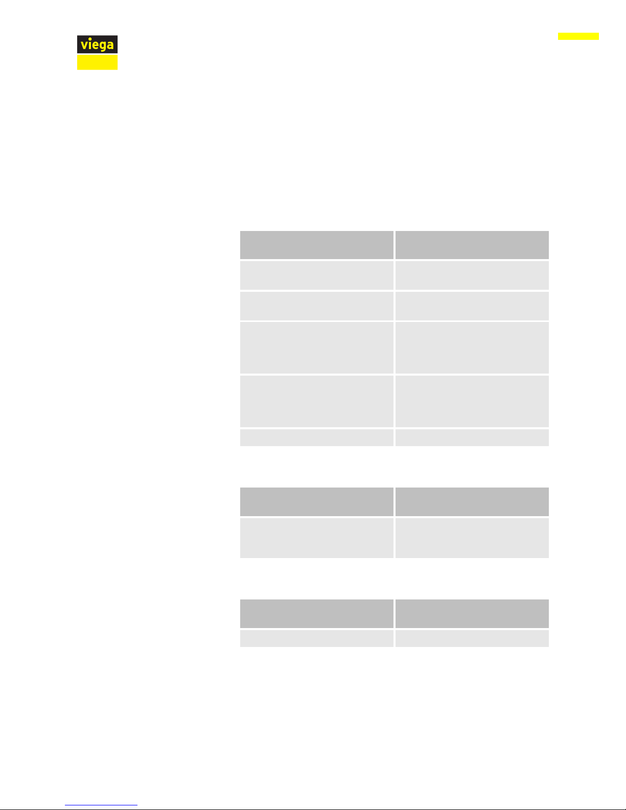
2.1 Standards and regulations
The following standards and regulations apply to Germany / Europe and
are provided as a support feature.
Regulations from section: Sealing
Scope / Notice Regulations applicable in Ger‐
many
Stress class of the underground,
as well as suitable bonded sealing
ZDB-Merkblatt 8/2012
Stress class of the underground,
as well as suitable bonded sealing
Leitfaden zur Abdichtung im Ver‐
bund (AIV)
Approved bonded sealings with
proof of practicability in keeping
with building law for stress
classes A and AO
ETAG 022 T1
Approved bonded sealings with
proof of practicability in keeping
with building law for stress
classes A, B and C
DIBt-Bauregelliste A, Teil 2 des
DIBt und Prüfgrundsätze für
Abdichtungen im Verbund
(PG AIV-F)
Permitted bonded sealings EN 14891
Regulations from section: Fields of application
Scope / Notice Regulations applicable in Ger‐
many
Specifications not met due to
water seal level and small
drainage capacity.
EN 1253-1
Regulations from section: Media
Scope / Notice Regulations applicable in Ger‐
many
Typical domestic wastewater DIN 1986-3
2.2 Intended use
2.2.1 Areas of use
The drain is designed for small to medium volumes of water, which
occur in e.g. residential building.
Product information
Advantix bath drain 6 from 21
Page 7
Technical information, see Ä Chapter 2.3.2 „Technical data“ on page 8.
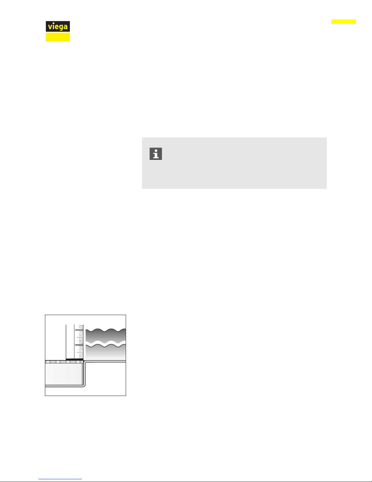
The drain with a horizontal drain socket is suitable for both mounting in
a floor opening as well as for mounting on the floor.
The side inlet not serves as an odour trap.
The water seal level of 30 mm and the small drainage
capacity do not meet the specifications pursuant to the
standards and regulations. See Ä „Regulations from sec‐
tion: Fields of application“ on page 6.
Check if the drainage capacity is sufficient before mounting!
2.2.2 Media
The drain is intended for draining of household-type wastewater in con‐
stant operation, see Ä „Regulations from section: Media“ on page 6.
n The short-term temperature of the wastewater may reach up to
95° C. The temperature must be considerably lower in constant
operation.
n The pH value must be higher than 4 but lower than 10.
It is not permitted to introduce wastewater which would damage the
product material.
2.2.3
Drainage capacity
Drainage capacity at an accumulation height of 10 mm above the grate:
0.45 l/s
Drainage capacity at an accumulation height of 20 mm above the grate:
0.5 l/s
Drainage capacity through the lateral inlet: 1.2 l/s
The values are dependent on the total height of the drain unit.
10
20
Product information
Advantix bath drain 7 from 21
Page 8

2.3 Product description
2.3.1 Overview
1
3
2
5 4
1 removable odour trap
2 flange for the application of the bonded sealing
3 horizontal drain socket (DN 50) with ball joint
4 Base unit
5 side inlet
2.3.2 Technical data
Nominal width [DN] (drain
socket)
50
Nominal width [DN] (inlet) 40
Drainage capacity
Ä
Chapter 2.2.3 „Drainage capacity“
on page 7
Dimensions and installa‐
tion height
Ä
Chapter 3.1.2 „Installation dimen‐
sions“ on page 15
Water seal level 30 mm
Load class corresponds with the load class of the top
used
2.4 Information for use
2.4.1 Installation variations
The mounting of the drain in a bare concrete floor is as follows:
Installing in a bare concrete floor
Product information
Advantix bath drain 8 from 21
Page 9

n The drain is placed in a floor recess and then cast-in.
During the mounting on the floor, the drain is integrated into the floor
construction. At the same time, it can e.g. be integrated into the level‐
ling screed or heat insulation. If necessary, a vertical drainpipe can be
led through a drill hole in the floor at the same time.
NOTICE!
The creation of a floor recess must be agreed with the fol‐
lowing people:
– a structural engineer
– the on-site fire protection inspector or the specialist
engineer for fire protection
If necessary, proof of compliance with building code or an
expert's report must exist.
Fig. 1: General installation example – Floor
recess
Mounting on a floor
Fig. 2: General mounting example – Mounting
on the floor
Product information
Advantix bath drain 9 from 21
Page 10

2.4.2 Sealing
To protect against moisture penetration, apply sealing foils, which are to
be processed in liquid state, directly below the tiles on screed and
walls. The determination of the stress class and the underground as well
as the selection of the suitable bonded sealing must be carried out in
compliance with the valid standards and regulations, see: Ä „Regula‐
tions from section: Sealing“ on page 6.
The bonded seal can be applied directly onto the drain flange.
Fig. 3: Diagram of a bonded seal
Bonded sealing
Product information
Advantix bath drain 10 from 21
Page 11

Careful planning is required for professional sealing. In addition,
depending on the individual dampness wear class and the type of foun‐
dation, a suitable thin bed bonded sealing with a building regulations
certificate of suitability must be chosen.
Furthermore, the following factors should be taken into account:
n Drain or shower channel must be equipped with a special flange,
which has an adhesive surface and a width of at least 30 mm.
n For bridging the material change from drain to screed, either a suit‐
able sealing collar or sealing tape designed for overlapping with the
thin bed bonded sealing over a width of at least 50 mm must be
used.
n The screed must be laid at a minimum incline of 1–2%.
n The installation must be carried out properly in acc. with the
mounting instructions and the manufacturer's information.
1-2%
1 2 43 5
8 67
Fig. 4: Construction diagram of the bonded seal - min. screed incline 1–2 %
1 Grate
2 Top piece with adhesive flange
3 Tile
4 Tile cement
5 Bonded sealing
6 Screed
7 sealing collar
8 adhesive
In connection with suitable drains, only approved bonded sealings with
proof of practicability in keeping with building law may be used. See
Ä
„Regulations from section: Sealing“ on page 6.
Information regarding the procedure can be found in the instructions for
use of the corresponding product.
Important note
Permitted bonded seals
Product information
Advantix bath drain 11 from 21
Page 12

2.4.3 Fire protection
Advantix shower channels and drains can both be fitted to be fire proof.
The R120 pipe lead-in can be used for this purpose in the floor con‐
struction. In this way, a fire resistance time of up to 120 minutes can be
achieved.
Fig. 5: Example: fire protection pipe lead-in
Mounting instruction of the R120 pipe lead-in see model 4923.5,
Art.-No. 491 673.
2.5
Required accessories
A top must be purchased separately to complete the mounting of the
drain.
Advantix tops are available in a number of sizes and variations. You can
also only buy an Advantix top frame and then purchase a suitable
designer grate separately (see catalogue).
Top
Product information
Advantix bath drain 12 from 21
Page 13

The drain can be fitted with a sieve insert (model 4958) to collect dirt.
Advantix drains can be equipped with an additional odour barrier, which
also closes the drain odour-tight, if the water seal in the odour trap has
evaporated. Odour nuisance is even avoided with drains that are only
seldom used. Odour barriers can be found in the catalogue.
Sieve insert
Odour barrier
Product information
Advantix bath drain 13 from 21
Page 14

3 Handling
3.1 Assembly information
3.1.1 Important note
Before assembly:
n Check if the drainage capacity of the drain is sufficient for the arising
water volume Ä Chapter 2.2.3 „Drainage capacity“ on page 7.
n Check if the installation height of the drain corresponds with the
planned floor construction.
n Ensure that the required connection line is installed with the neces‐
sary incline to the planned installation location.
n If necessary, supply the required accessories Ä Chapter 2.5
„Required accessories“ on page 12.
During assembly:
n Observe installation dimensions.
After assembly:
n The drain flange must be fully lined with mortar.
Handling
Advantix bath drain 14 from 21
Page 15

3.1.2 Installation dimensions
Fig. 6: Dimensional drawing model 4938
3.1.3 Tools and materials
n Top with grate, if not included in scope of delivery Ä Chapter 2.3.1
„Overview“ on page 8
n Material for securing the drain
3.2 Assembly
3.2.1 Connecting the drain
The connection to the wastewater system must be completed before
the drain can be installed in the floor construction. Proceed as follows:
Requirements:
n A pipe to the planned drainage position is already in place for the
connection to the wastewater system.
n The drainpipe has an internal sealing lip.
Required material
Connecting to the wastewater system
Handling
Advantix bath drain 15 from 21
Page 16

Push the drain socket into the drainpipe completely.
The connection to the inlet must first be made to be able to mount the
drain. Proceed as follows:
Requirements:
n Inlet pipe has been mounted.
Unscrew the union nut from the drain inlet.
Remove protective plug.
Remove sliding ring and sealing from the protective plug.
Connecting the inlet
Handling
Advantix bath drain 16 from 21
Page 17

Push the union nut, sliding ring and sealing onto the inlet pipe.
Push inlet pipe at least 1.5 cm deep into the drain inlet.
Screw the inlet pipe with the coupling onto the drain inlet.
3.2.2 Preparing for subsequent work
A few points must be observed to integrate the drain into the floor con‐
struction properly. For this reason, proceed as follows to prepare the
drain for subsequent work:
Requirements:
n The drain is connected.
n The inlet is connected.
n The protective foil and the yellow protective plugs are to be found,
undamaged, on the drain.
Position the drain at the desired height at the place of use. It is
important that the upper edge of the drain flange is flush with the
upper edge of the sealing layer. If necessary, raise or lower the drain
in the existing floor using suitable material.
Align drain horizontally using a spirit level.
Secure the drain in such a way that it cannot shift when the subse‐
quent works are applied.
Most importantly, it must be ensured that the drain does not float
when the concrete or screed is poured in.
Handling
Advantix bath drain 17 from 21
Page 18

NOTICE!
Product damage due to improper installation
If hollow spaces occur during the lining of the drain, leaks
may occur when pressure is applied.
Inform the subsequent workers that the drain must be fully
lined and that there must be no hollow spaces.
3.2.3 Sealing the drain
NOTICE!
Product damage due to improper installation
If hollow spaces occur during the lining of the drain, leaks
may occur when pressure is applied.
Check the proper completion of the subsequent work.
Screed and floor tiles must be laid at an incline of 1–2 % in
the direction of the drain.
Requirements:
n The flange is free of heavy soil.
n The complete surface of the flange is lined with material and undam‐
aged.
Remove protective foil.
Bonded sealing
Handling
Advantix bath drain 18 from 21
Page 19

Apply the bonded sealing on the dry screed and spread to the inner
edge of the flange fleece.
NOTICE! Observe the bonded sealing manufacturer's
instructions for use.
Lay the sealing collar into the bonded sealing.
Apply a second layer of bonded sealing onto the sealing collar and,
if necessary, onto the floor.
3.2.4
Mounting the top
The top with the grate must still be mounted to finish off the mounting of
the drain. Proceed as follows:
Handling
Advantix bath drain 19 from 21
Page 20

Calculate the height of the floor construction from the edge in the
inside of the drain up to the upper edge of the tiles.
Starting with the upper edge, transfer the measured height onto the
top.
Cut the top to the marked height.
INFO! No backflow seal may be fitted so that any seepage that
may occur can drain off without hindrance!
Remove yellow protective plug.
Place the top into the drain and align according to the tiles.
Work the top into the screed or the floor covering.
3.3
Care
3.3.1 Care tips
Normal soap or a mild cleaning agent can be used for regular mainte‐
nance and prevention of lime scale on the grate and frame. Use no
scouring agent or abrasive objects.
Strong stains, even around the drain unit and the siphon, can be
removed using typical household cleaner. Rinse the detergent very thor‐
oughly with clear water after the prescribed dwell time. There should be
no residue on the components.
3.3.2
Cleaning the drain
We recommend using a mild cleaning agent and a washing-up brush for
cleaning.
Handling
Advantix bath drain 20 from 21
Page 21

Remove and clean grate.
Remove and clean immersion pipe.
Clean drain.
Replace immersion pipe.
Re-insert grate.
3.4
Disposal
Separate the product and packaging materials (e. g. paper, metal,
plastic or non-ferrous metals) and dispose of in accordance with valid
national legal requirements.
Handling
Advantix bath drain 21 from 21
 Loading...