

Page 1
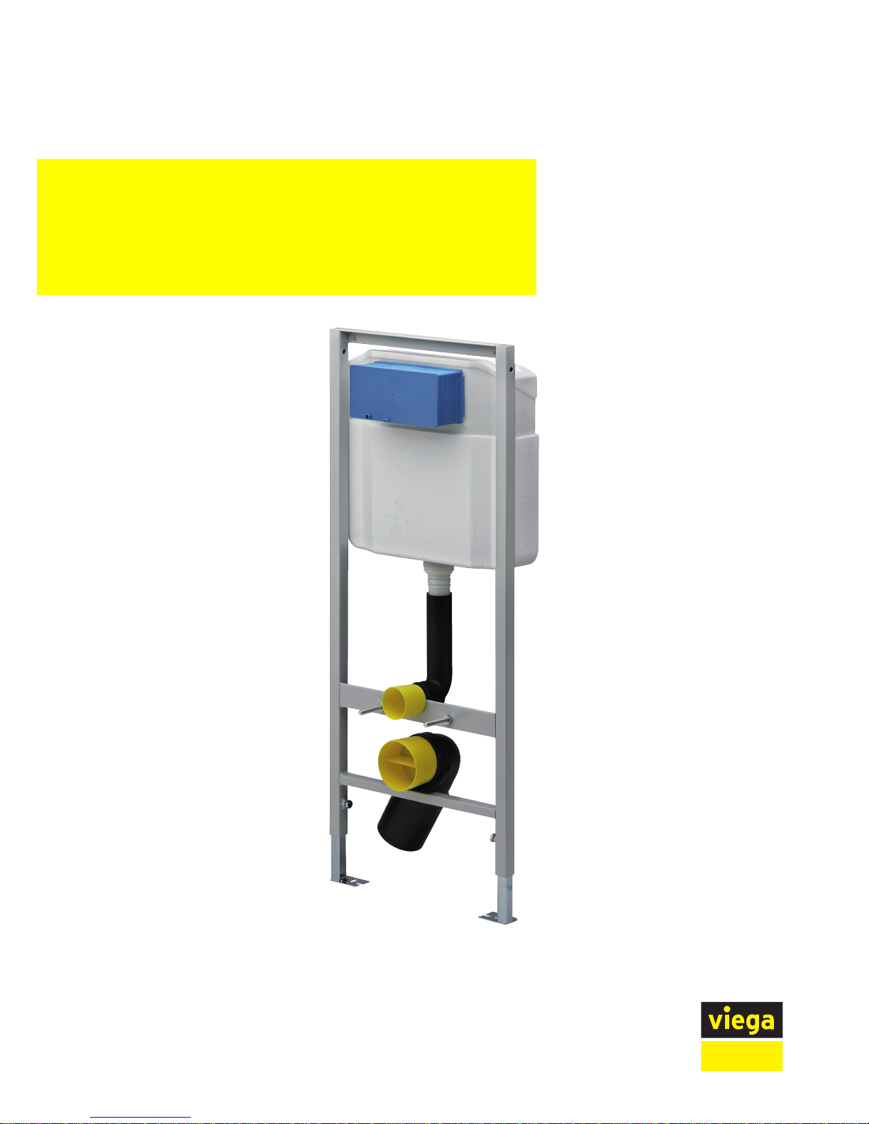
Viega Eco Plus
Model Year built:
8180.26 from 08/2007
en_INT
Viega Eco WC element
Instructions for Use
Page 2

Viega Eco WC element 2 from 26
Page 3
Table of contents
1 About this instruction for use 4
1.1
Target groups 4
1.2
Labelling of notes 4
1.3
About this translated version 5
2 Product information 6
2.1
Intended use 6
2.1.1
Areas of use 6
2.2
Product description 6
2.2.1
Overview 6
2.2.2
Compatible components 7
2.2.3
Sound protection 8
2.2.4
Technical data 8
2.3
Accessories 9
3 Handling 10
3.1
Assembly information 10
3.1.1
Mounting conditions 10
3.1.2
Installation dimensions 11
3.1.3
Required tools 11
3.2
Assembly 12
3.2.1
Mounting WC element 12
3.2.2
Connecting concealed cistern 19
3.2.3
Preparing optional actuation versions 24
3.2.4
Setting the flush volume 25
3.3
Cleaning and maintenance 26
3.4
Disposal 26
Table of contents
Viega Eco WC element 3 from 26
Page 4

1 About this instruction for use
Trade mark rights exist for this document, further information can be
found at www.viega.com/legal-notices.
1.1 Target groups
The information in this instruction manual is directed at the following
groups of people:
n Heating and sanitary professionals and trained personnel
n Operators
n Consumers
n Drywall builder
It is not permitted for individuals without the abovementioned training or
qualification to mount, install and, if required, service this product. This
restriction does not extend to possible operating instructions.
The installation of Viega products must take place in accordance with
the general rules of engineering and the Viega instructions for use.
1.2
Labelling of notes
Warning and advisory texts are set aside from the remainder of the text
and are labelled with the relevant pictographs.
DANGER!
This symbol warns against possible life-threatening injury.
WARNING!
This symbol warns against possible serious injury.
CAUTION!
This symbol warns against possible injury.
NOTICE!
This symbol warns against possible damage to property.
About this instruction for use
Viega Eco WC element 4 from 26
Page 5

Notes give you additional helpful tips.
1.3 About this translated version
This instruction for use contains important information about the choice
of product or system, assembly and commissioning as well as intended
use and, if required, maintenance measures. The information about the
products, their properties and application technology are based on the
current standards in Europe (e. g. EN) and/or in Germany
(e. g. DIN/DVGW).
Some passages in the text may refer to technical codes in Europe/
Germany. These should serve as recommendations in the absence of
corresponding national regulations. The pertinent national laws, standards, regulations and guidelines, as well as other technical guidelines,
have priority over German/European guidelines in this manual: The
information is not binding for other countries and territories and should,
as mentioned, be considered as support.
About this instruction for use
Viega Eco WC element 5 from 26
Page 6
2 Product information
2.1 Intended use
2.1.1 Areas of use
The Viega Eco Plus WC element is suitable for mounting on wall constructions in acc. with DIN EN 1996-1-1, DIN 1045 and support profiles
in acc. with DIN 18183.
2.2 Product description
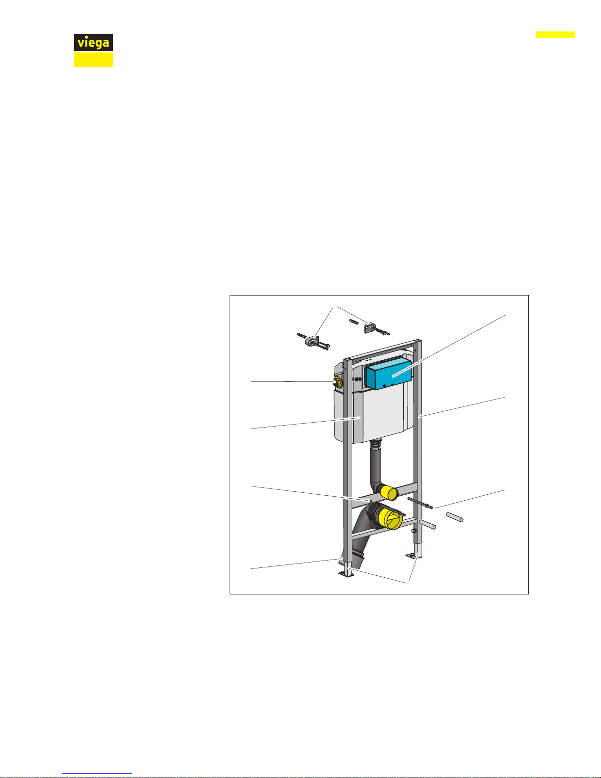
2.2.1 Overview
The WC element is equipped as follows:
2
1
9
8
3
5
6
7
4
Fig. 1: Components
1 - Viega Eco WC element
2 - threaded rods for fixing sanitary objects
(gauges for bore hole 180 mm)
3 - adjustable feet
4 - drain elbow
5 - fixing height for the WC ceramic 330 mm
6 - Viega concealed cistern 2S
7 - water connection
8 - fixing set (not included in the scope of delivery model 8173)
9 - flush actuation site protection
Product information
Viega Eco WC element 6 from 26
Page 7
2.2.2 Compatible components
The WC element is compatible with all common WC ceramics, even
with larger projection (barrier-free).
WCs with a fixing gauge for bore holes of 230 mm are not included.
The WC element can be extended by the following compatible components:
n odour extraction via flushing pipe (model 8310.26)
n connection installation set (model 8350.14)
n drain valve set (model 8180.0)
Mount the components in accordance with the instructions for use of
the components.
The odour extraction is suitable for the reduction of odour nuisance in
inside bathrooms and heavily frequented toilet facilities. The odour
extraction is directly connected to the ventilation system.
The installation set is suitable for the connection of an electrical actuation. The installation set consists of an empty pipe, a cavity wall socket
and the relative, required clip. The empty pipe connects the cavity wall
socket with the concealed cistern.
The drain valve set is suitable for the conversion to a flush plate from
the Visign for Style or Visign for More series. The drain valve set consists of the drain valve with drain valve seat and bow, an actuating
mechanism (dual-flush function) and an actuating rod set. The new
fixing panel can be used after the installation of the drain valve set.
Product
Name Model number
Standard Flush plate Standard 1 8180.1
Visign for Style Flush plate
Visign for Style 10
8315.1
Flush plate
Visign for Style 13
8333.1
Flush plate
Visign for Style 14
8334.1
Odour extraction
Connection installation set
Drain valve set
Compatible flush plates
Product information
Viega Eco WC element 7 from 26
Page 8
Product Name Model number
Visign for Public Flush plate
Visign for Public 1
8326.1
cover plate 8326.9
Further compatible flush plates if using drain set 8180.0:
Product Name Model number
Visign for Style Flush plate
Visign for Style 11
8331.1
Flush plate
Visign for Style 12
8332.1
Flush plate
Visign for Style 12
8332.4
Visign for More Flush plate
Visign for More 100
8352.1
Flush plate
Visign for More 101
8351.1
Flush plate
Visign for More 102
8353.1
Flush plate
Visign for More 103
8355.1
Flush plate
Visign for More 104
8354.1
2.2.3 Sound protection
The WC element fulfils the requirements in acc. with DIN 4109 as well
as the increased requirements in acc. with
DIN 4109 (supplementary sheet 2) and the requirements in acc. with
VDI 4100 SSt I-SSt III.
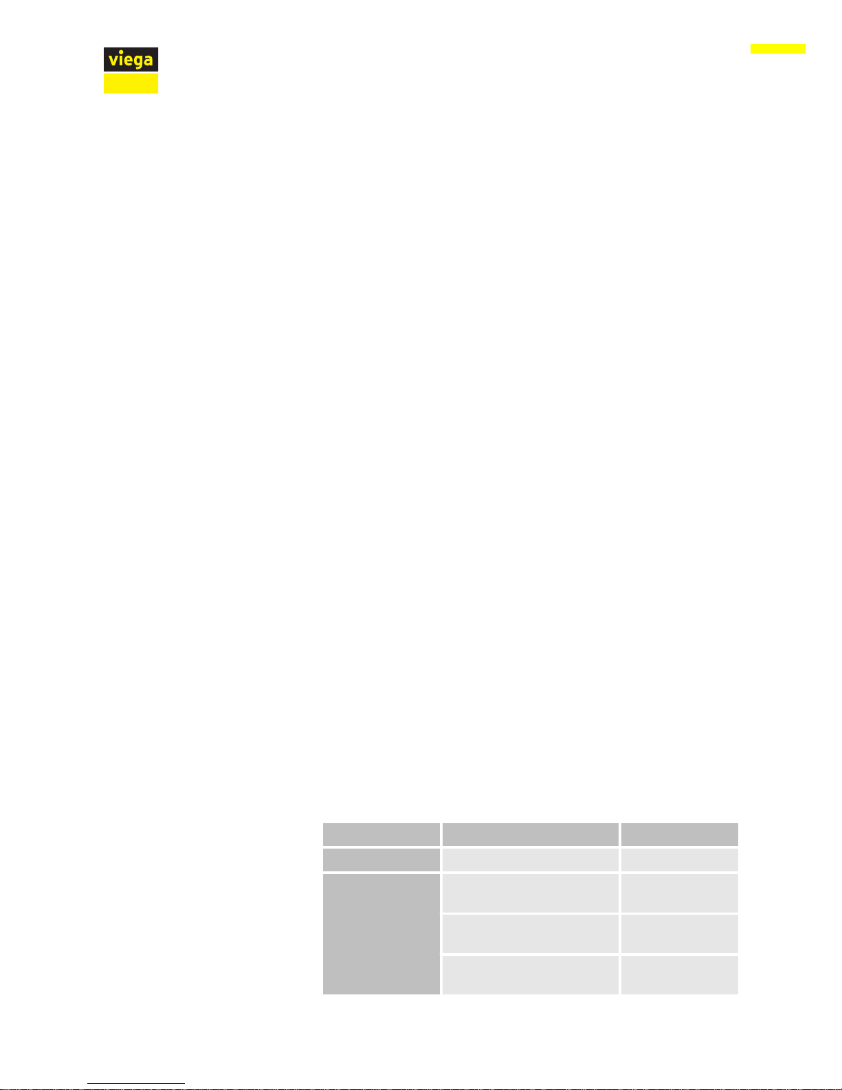
2.2.4 Technical data
Small flush volume Factory setting approx. 3 l
Setting range approx. 3–4 l
Large flush volume Factory setting approx. ca. 6 l
adjustable to approx. 9 l
Flush volume
Product information
Viega Eco WC element 8 from 26
Page 9

2.3 Accessories
The fixing set model 8173 is required to secure.
Required accessories
Product information
Viega Eco WC element 9 from 26
Page 10

3 Handling
3.1 Assembly information
3.1.1 Mounting conditions
The WC element can be mounted on the following walls:
n masonry walls in acc. with DIN EN 1996-1-1
n concreted walls in acc. with DIN 1045
n metal support profile in acc. with DIN 18183
The WC element may only be mounted on even wall surfaces.
With the construction height, the marked height of the upper edge of
the finished floor must be observed.
The WC element can only be used in combination with wall-hung WCs
(fixing gauges for bore hole 180 mm).
The WC element can be extended by a remote actuation
Visign for Public1 (model 8326.21) or by an electronic actuation (model
8350.31 or 8350.32). The corresponding actuation method must be prepared before the WC element is clad and tiled.
The corresponding empty pipe (included in the scope of delivery of the
remote actuation) is required when preparing the remote actuation
Visign for Public1.
Suitable walls
Construction height
WC ceramic
Actuation
Handling
Viega Eco WC element 10 from 26
Page 11

3.1.2 Installation dimensions
3.1.3 Required tools
The following tools are required for mounting the WC element:
n
drill with 10 mm drill bit
n ratchet with sockets: 13 mm / 17 mm
n fork or ring spanner: 10 mm / 13 mm / 17 mm / 19 mm
n fork or ring spanner: 27 mm
Dimensions
Handling
Viega Eco WC element 11 from 26
Page 12

3.2 Assembly
3.2.1 Mounting WC element
Determine and mark fixing points.
x1: 390 mm
x2: 1110 mm.
Drill holes.
Attach fixing set with the fork spanner (size 13).
Masonry wall
X1
0-200
0-200
0
1000
0
Ø10
X2
1
3
Handling
Viega Eco WC element 12 from 26
Page 13

Align the height of the feet with a fork spanner (size 17).
Mark fixing points on the floor.
Remove WC element and drill floor holes.
Align the WC element in accordance with the cutting check.
Attach WC element to the floor using the fork spanner (size 13) and
the screws and dowels supplied.
Set the installation depth of the WC element (130–200 mm) with the
fork spanner (size 17).
17
Ø10
13
17
Handling
Viega Eco WC element 13 from 26
Page 14

Screw in the threaded rods for WC ceramic.
Clip in drain elbow.
Install site protection of the flush actuation.
Pull the plastic protective sleeves for the threaded rods over the WC
ceramic.
Mount protective plug.
If necessary mount a reducer.
Carry out water connection.
click
1
9
Handling
Viega Eco WC element 14 from 26
Page 15

Double clad WC element with IFGP cladding panels (model 8055.10)
(2 x 12.5 mm).
2x
Handling
Viega Eco WC element 15 from 26
Page 16

If necessary, adjust (pre-mounted) foot depth from 75 mm to
50 mm.
Pull the foot out and turn by 90°.
Determine construction height in accordance with the on-site
marking of the upper edge of the finished floor.
Pull WC element up (cutting check) and align.
Tighten feet with the fork spanner (size 17).
Mark holes for floor supports.
On-site support profile
75
90°
50
1
7
0-200
0
1000
Handling
Viega Eco WC element 16 from 26
Page 17

Drill holes.
Secure WC element to floor (size 13).
Attach WC element to the support profiles using the screws supplied.
Connect the WC element flush with the support profiles.
Ø10
1
3
4x
Handling
Viega Eco WC element 17 from 26
Page 18

Screw in the threaded rods for WC ceramic
Clip in drain elbow.
Install site protection of the flush actuation.
Pull the plastic protective sleeves for the threaded rods over the WC
ceramic.
Mount protective plug.
If necessary mount a reducer.
Carry out water connection.
19
click
Handling
Viega Eco WC element 18 from 26
Page 19

Strap the support profiles with panel strips (≥ 30 cm).
Double clad WC element with IFGP cladding panels (model 8055.10)
(2 x 12.5 mm).
3.2.2 Connecting concealed cistern
If there is not enough space when pressing the water connection, the
water connection can be pulled out to the side.
Screw the ½ inch connector into the wall lead-in.
Counter with a fork spanner (SW 27).
≥ 30
2x
Laterally extricable water connection
Handling
Viega Eco WC element 19 from 26
Page 20

Loosen plastic union nut.
Pull out wall lead-in.
Press connection.
Push wall lead-in back into the plastic clamp.
The position of the key surface (SW 25) must be up or down.
The clicking into the groove signals the correct position.
Re-tighten the union nut.
Loosen (SW 19) flexible hose onto the filling valve.
Open corner valve.
Flush pipeline.
Handling
Viega Eco WC element 20 from 26
Page 21

Close corner valve.
Re-mount (SW 19) the flexible hose onto the filling valve.
Handling
Viega Eco WC element 21 from 26
Page 22

Loosen (SW 19) flexible hose onto the corner valve.
Unscrew plastic union nut.
Pull the corner valve inwards out of the wall lead-in.
Remove plastic union nut.
Remove the wall lead-in inwards.
Conversion water connection upwards (optional)
Handling
Viega Eco WC element 22 from 26
Page 23

Loosen the closing cap on the left-hand upper side of the concealed
cistern.
Close opening on the side with the closing cap.
Push wall lead-in from inside into the upper opening.
Insert the corner valve back into the wall lead-in.
Handling
Viega Eco WC element 23 from 26
Page 24

Screw plastic union nut back onto wall lead-in.
Re-mount (SW 19) the flexible hose onto the corner valve.
3.2.3 Preparing optional actuation versions
The corresponding empty pipe (included in the scope of delivery of the
remote actuation) is required when preparing the remote actuation
Visign for Public1 (model 8326.21).
Lead the empty pipe from the hollow wall socket into the concealed
cistern.
Distance from the remote actuation to the cistern (x)
n min. 1.0 m
n max. 1.7 m
A corresponding empty pipe (not included in the scope of delivery of the
electrical actuation) is required for the preparation of the electrical
actuation (model 8350.31 or model 8350.32).
Prepare remote actuation
X
X
Prepare electrical actuation
Handling
Viega Eco WC element 24 from 26
Page 25

Lead empty pipe from the switch or button into the concealed cistern, to connect the concealed socket and concealed cistern.
Positioning of the cistern power pack
n X1= max. 0.75 m
n X2= max. 2.75 m with an extension cable, 1 x article number 628 505
n X3= max. 4.75 m with two extension cables, 2 x article number 628
505
3.2.4 Setting the flush volume
Immediate re-flushing of the flush volume is possible at the
factory settings.
The WC element is factory-set at a small flush of approx. 3 l. The small
flush volume can be set at three levels: approx. 3 l / 3.5 l / 4 l.
Remove the drain valve from the concealed cistern.
Push the slide control on the side of the overflow pipe to the desired
small flush volume:
n
Top position: approx. 3 l
n Middle position: approx. 3.5 l
n Bottom position: approx. 4 l
The positions can be identified by the notches.
The WC element is factory-set at a large flush volume of approx. 6 l. The
large flush volume can be set continuously from approx. 6 l up to
approx. 9 l.
Remove the drain valve from the concealed cistern.
X1
X2
X3
Small flush volume
Large flush volume
Handling
Viega Eco WC element 25 from 26
Page 26

Push the slide control below the drain valve to the desired large
flush volume:
n left: approx. 6 l
n right: approx. 9 l
3.3 Cleaning and maintenance
Cleaning work may only be carried out by specialist trade professionals
or qualified experts.
In consideration of the mechanical, chemical and physical conditions,
the concealed cistern is constantly laden.
For this reason, the components must be cleaned, as required, and the
drain and filling valve seals renewed.
In areas or regions with hard water due to calcium or magnesium salts,
there is the risk of limescale deposits developing on the inlet and drain
valves.
The valves may have to be replaced, depending on the extent of
deposits.
3.4
Disposal
Separate the product and packaging materials (e. g. paper, metal,
plastic or non-ferrous metals) and dispose of in accordance with valid
national legal requirements.
Cleaning and maintenance of the concealed cistern
Handling
Viega Eco WC element 26 from 26
 Loading...