

Page 1
Advantix Vario base unit, for Advantix Vario
shower channel, can be cut to length con‐
tinuously
Instructions for Use
for bonded sealing (tiled shower) with sealing mat
Model Year built:
4965.10 from 01/2012
en_INT
Page 2

Advantix Vario base unit, for Advantix Vario shower channel, can be cut to length continuously 2 from 50
Page 3

Table of contents
1 About these instructions for use 5
Table of contents
1.1
1.2
1.3
Target groups 5
Labelling of notes 5
About this translated version 6
2 Product information 7
2.1
2.2
2.2.1
2.2.2
2.2.3
2.3
2.3.1
2.3.2
2.3.3
2.3.4
2.4
2.4.1
2.4.2
2.5
Standards and regulations 7
Intended use 8
Areas of use 8
Media 8
Drainage capacity 9
Product description 9
Installation variations 9
Overview of the components 13
Technical data 15
Sound protection 15
Information for use 16
Sealing 16
Fire protection 18
Required accessories 18
3 Handling 19
3.1
3.1.1
3.1.2
3.1.3
3.1.4
3.2
3.2.1
3.2.2
3.2.3
3.2.4
3.2.5
3.2.6
3.2.7
3.2.8
3.2.9
Advantix Vario base unit, for Advantix Vario shower channel, can be cut to length continuously 3 from 50
Assembly information 19
Important note 19
Tools and materials 19
Installation dimensions 20
Recommended procedure 22
Assembly 22
Calculating the profile length in niche installation 22
Shortening the profile 24
Mounting the closing caps on base unit 26
Pre-mounting extending parts 26
Determine height 30
Mounting feet and drain socket 31
Aligning and connecting 34
Preparing for further work 38
Sealing the shower channel 39
Page 4

Table of contents
3.2.10
3.2.11
3.3
3.3.1
3.3.2
3.4
Inserting the sieve 45
Mounting the standing grate 45
Care 48
Care tips 48
Cleaning 49
Disposal 50
Advantix Vario base unit, for Advantix Vario shower channel, can be cut to length continuously 4 from 50
Page 5
About these instructions for use
1 About these instructions for use
Trade mark rights exist for this document; for further information, go to
viega.com/legal.
1.1 Target groups
The information in this instruction manual is directed at the following
groups of people:
n Heating and sanitary professionals and trained personnel
n Tilers
n Consumers
Individuals without the abovementioned training or qualification are not
permitted to mount, install and, if required, maintain this product. This
restriction does not extend to possible operating instructions.
1.2
The installation of Viega products must take place in accordance with
the general rules of engineering and the Viega instructions for use.
Labelling of notes
Warning and advisory texts are set aside from the remainder of the text
and are labelled with the relevant pictographs.
DANGER!
This symbol warns of possible life-threatening injury.
WARNING!
This symbol warns of possible serious injury.
CAUTION!
This symbol warns of possible injury.
NOTICE!
This symbol warns of possible damage to property.
This symbol gives additional information and hints.
Advantix Vario base unit, for Advantix Vario shower channel, can be cut to length continuously 5 from 50
Page 6

1.3 About this translated version
This instruction for use contains important information about the choice
of product or system, assembly and commissioning as well as intended
use and, if required, maintenance measures. The information about the
products, their properties and application technology are based on the
current standards in Europe (e. g. EN) and/or in Germany
(e. g. DIN/DVGW).
Some passages in the text may refer to technical codes in Europe/
Germany. These should serve as recommendations in the absence of
corresponding national regulations. The relevant national laws, stand‐
ards, regulations, directives and other technical provisions take priority
over the German/European directives specified in this manual: The
information herein is not binding for other countries and regions; as said
above, they should be understood as a recommendation.
About these instructions for use
Advantix Vario base unit, for Advantix Vario shower channel, can be cut to length continuously 6 from 50
Page 7

2 Product information
2.1 Standards and regulations
The following standards and regulations apply to Germany / Europe.
National regulations can be found on the relevant web site of your
country at viega.com/standards.
Regulations from section: Sealing
Scope / Notice Regulations applicable in Ger‐
Product information
many
Stress class of the underground,
as well as suitable bonded sealing
Stress class of the underground,
as well as suitable bonded sealing
Approved bonded sealings with
proof of practicability in keeping
with building law for stress
classes A and AO
Approved bonded sealings with
proof of practicability in keeping
with building law for stress
classes A, B and C
Permitted bonded sealings EN 14891
Regulations from section: Drainage capacity
Scope / Notice Regulations applicable in Ger‐
Drainage capacity collective con‐
nection DN 50
ZDB-Merkblatt 8/2012
Leitfaden zur Abdichtung im Ver‐
bund (AIV)
ETAG 022 T1
DIBt-Bauregelliste A, Teil 2 des
DIBt und Prüfgrundsätze für
Abdichtungen im Verbund
(PG AIV-F)
many
DIN 1986-100
Drainage capacity collective con‐
nection DN 70
Regulations from section: Media
Scope / Notice Regulations applicable in Ger‐
Typical domestic wastewater DIN 1986-3
Advantix Vario base unit, for Advantix Vario shower channel, can be cut to length continuously 7 from 50
DIN 1986-100
many
Page 8

Product information
Regulations from section: Sound protection
Scope / Notice Regulations applicable in Ger‐
many
2.2 Intended use
2.2.1 Areas of use
Fulfilled noise protection require‐
ments
Fulfilled noise protection require‐
ments
Regulations from section: Important notes
Scope / Notice Regulations applicable in Ger‐
Dimensions of slots and recesses EN 1996
The shower channel is used in the bathroom as a drain for a floor-level
shower. It is designed for small to medium volumes of water, which
occur in e. g. residential building.
DIN 4109
VDI 4100
many
2.2.2
Technical information, see Ä Chapter 2.3.3 „Technical data“
on page 15.
Media
The shower channel is intended for draining of household-type waste‐
water in constant operation, see Ä „Regulations from section: Media“
on page 7.
n The short-term temperature of the wastewater may reach up to
95° C. The temperature must be considerably lower in constant
operation.
n The pH value must be higher than 4 but lower than 10.
It is not permitted to introduce wastewater which would damage the
product material.
Advantix Vario base unit, for Advantix Vario shower channel, can be cut to length continuously 8 from 50
Page 9

2.2.3 Drainage capacity
For assembly with one drain
Product information
Accumulation
height
10 mm 0.45 l/s 0.75 l/s 0.4 l/s 0.7 l/s
20 mm 0.5 l/s 0.8 l/s 0.45 l/s 0.75 l/s
For mounting with collective connection (two or three drains)
without sieve insert
Installation height
95 mm
without sieve insert
Installation height
165 mm
When two or three drains are combined using a collective connection
and a drainage capacity of > 0.8 l/s is expected, the dimensioning of the
drainpipe must be DN 70.
The drainage capacity of the
collective connection in DN 50
The drainage capacity of the
collector line in DN 70
with sieve insert
Installation height
95 mm
0.4–0.8 l/s (95–165 mm installation
height)
up to 0.8 l/s, see Ä „Regulations
from section: Drainage capacity“
on page 7
two or three drains: 0.8–1.6 l/s
(95–165 mm installation height), see
Ä
„Regulations from section:
Drainage capacity“ on page 7
with sieve insert
Installation height
165 mm
2.3 Product description
2.3.1 Installation variations
The length and shape of the Advantix Vario shower channel
can be variably adapted. Use the shower channel configu‐
rator to calculate the material required for any design avail‐
able: http://advantix-vario.viega.de/
The length of the shower channel can be adapted to suit:
n The base unit can be shortened to a length of 300 mm with milli‐
metre precision.
n The length of the shower channel can be extended up to 2800 mm
by installing accessory parts.
The shower channel can be altered in the following way using the fol‐
lowing accessories:
Advantix Vario base unit, for Advantix Vario shower channel, can be cut to length continuously 9 from 50
Page 10
1
2 3
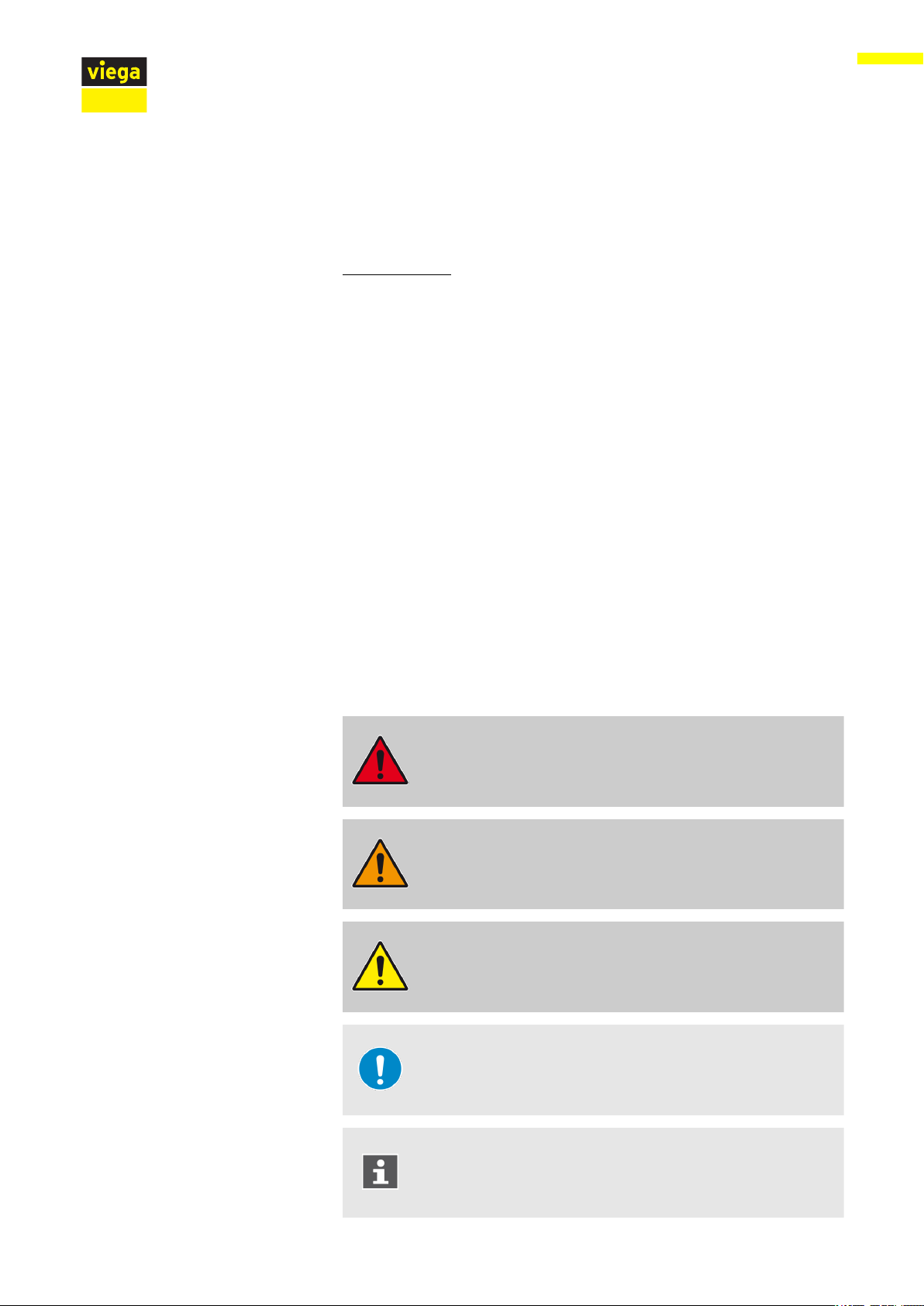
Fig. 1: Installation possibilities
1 2
3
1 straight version, also possible with two base units
2 L-version
3 U-version
Product information
Extension parts
The following parts are available for individual shower channel design:
1 end closing piece, 275 mm
2 connection piece, 210 mm
3 connection piece 90°, 290 x 290 mm
Advantix Vario base unit, for Advantix Vario shower channel, can be cut to length continuously 10 from 50
Page 11
a
b
c
d
a
b
d
c
Product information
end closing piece
Instead of the closing cap, a long element, the so-called "end closing
piece" can be mounted onto the base unit. The base unit can therefore
be extended accordingly.
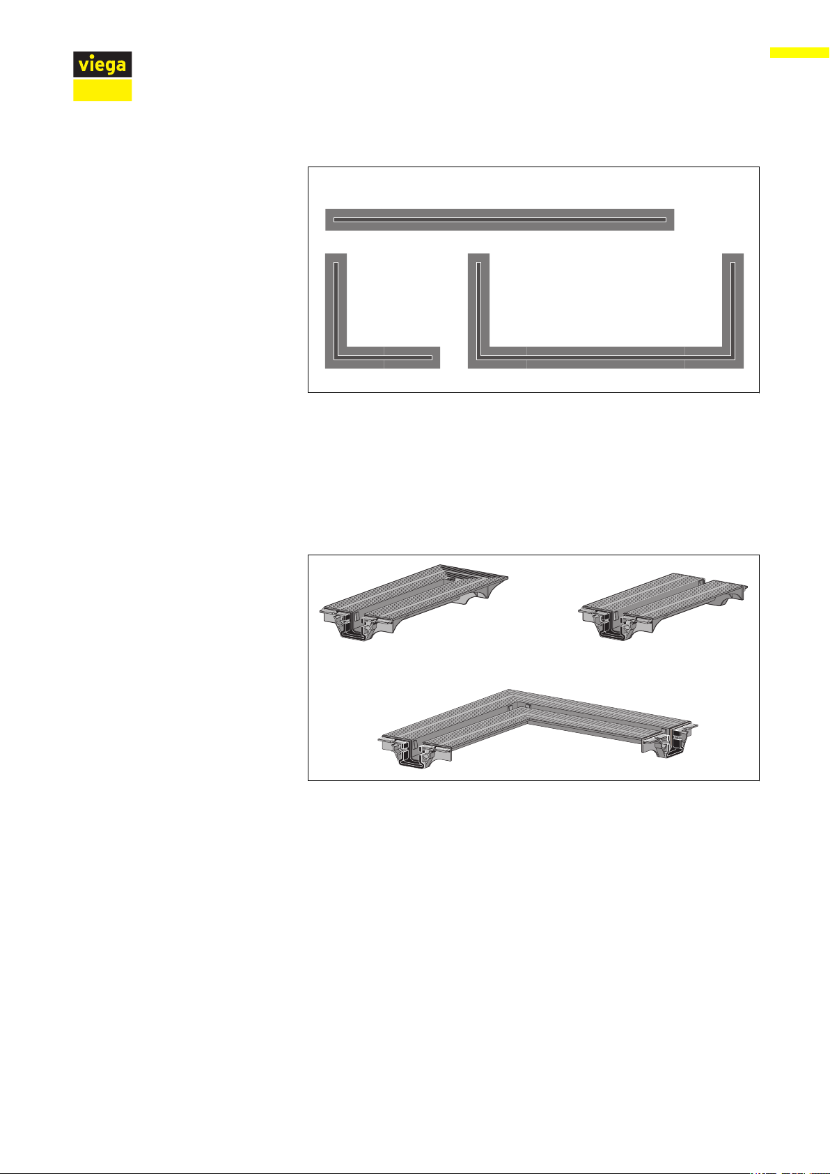
Fig. 2: Installation possibilities with end closing piece
a max. 1451 mm
b max. 1680 mm
c max. 2651 mm
d max. 2880 mm
Connection piece
The connection piece serves the purpose of joining two base units
together. In this case, one of the base unit units must be shortened by
the length of the connection piece (= 210 mm).
– The connection piece may not be shortened.
– The connection piece may not be used with the L or U
versions.
Fig. 3: Models with connection piece
a min. 831 mm
b max. 2422 mm
c max. 2651 mm
d max. 2880 mm
Advantix Vario base unit, for Advantix Vario shower channel, can be cut to length continuously 11 from 50
Page 12
1
2
a b
b
a
1
2
a c
a c
b b
Product information
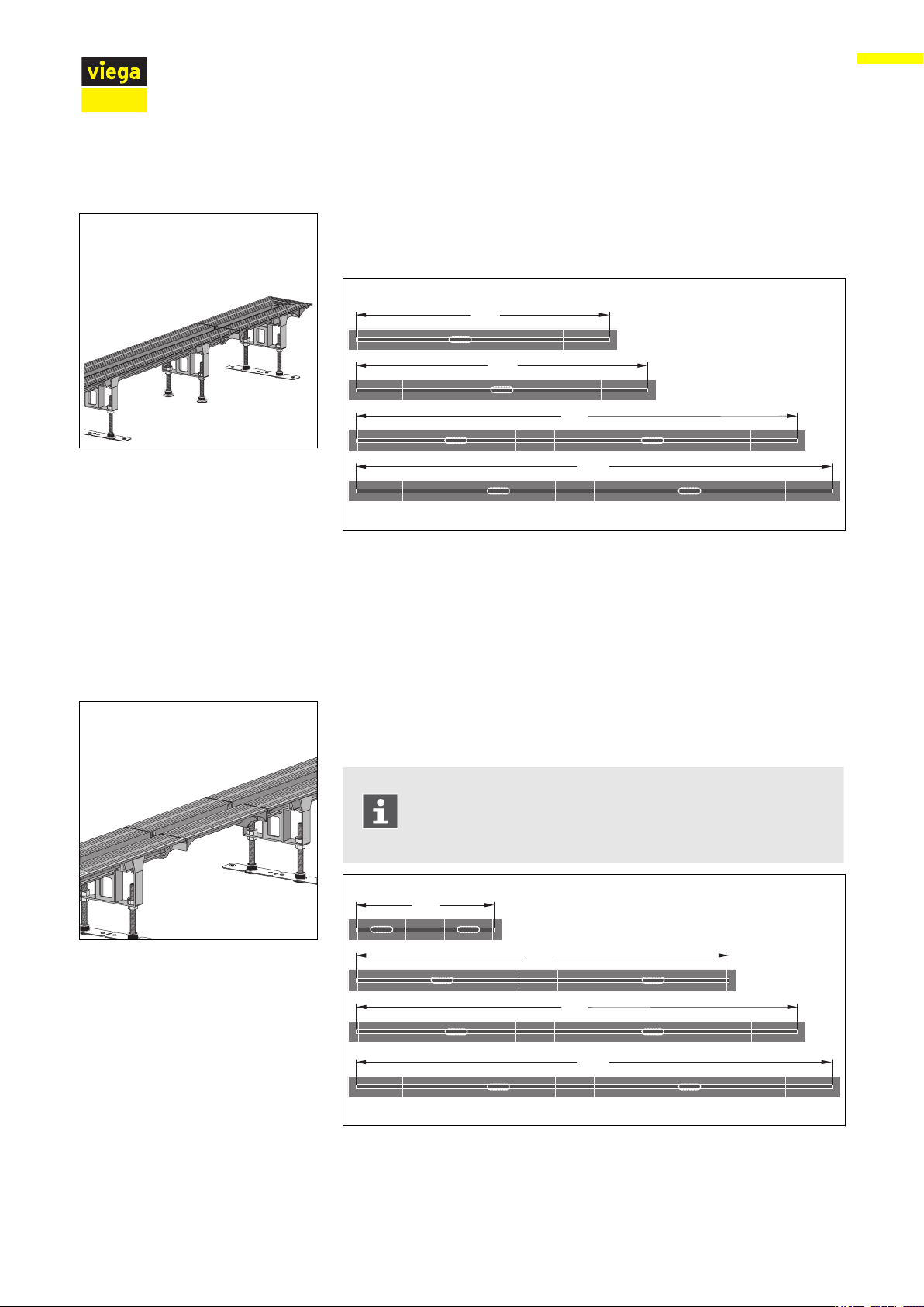
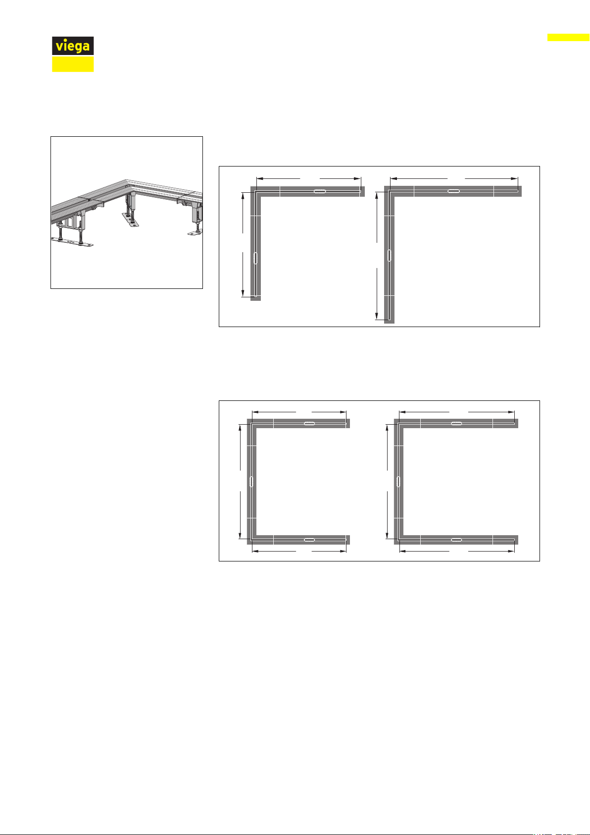
Connection piece 90°
The connection piece 90° enables the mounting shower channels in Lor U-models.
Fig. 4: Installation possibilities with connection pieces 90° for L version
1 with closing caps
2 with end closing pieces
a 557–1457 mm
b max. 1686 mm
Fig. 5: Installation possibilities with connection pieces 90° for U version
1 with closing caps
2 with end closing pieces
a 557–1457 mm
b 792–1692 mm
c max. 1686 mm
Advantix Vario base unit, for Advantix Vario shower channel, can be cut to length continuously 12 from 50
Page 13
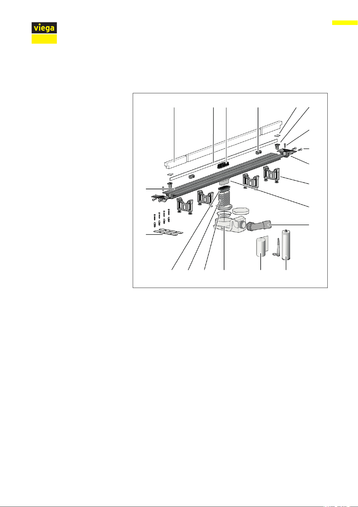
2.3.2 Overview of the components
1 2 3 4 5 6
7
8
9
10
11
12
131415161718
19
20
Basic model
Product information
Fig. 6: Components and scope of delivery
1 protective insert made of hard foam
2 standing grate*
3 sieve*
4 grate supports*
5 cover caps*
6 grate holder*
7 screws for adjusting the feet*
8 fixing screws
9 closing cap
10 feet
11 base unit with drain socket
12 connection elbow 40/50
13 mounting adhesive
14 sealing tape
15 odour trap
16 O-rings
17 height adjustment piece
18 seal
19 fixing material
20 flange
— bag with grease
— 1 size 4 bit
* not included in scope of delivery
Advantix Vario base unit, for Advantix Vario shower channel, can be cut to length continuously 13 from 50
Page 14
1
2
3
4
1
2
3
4
7
6
5
8
9
Extension parts
Product information
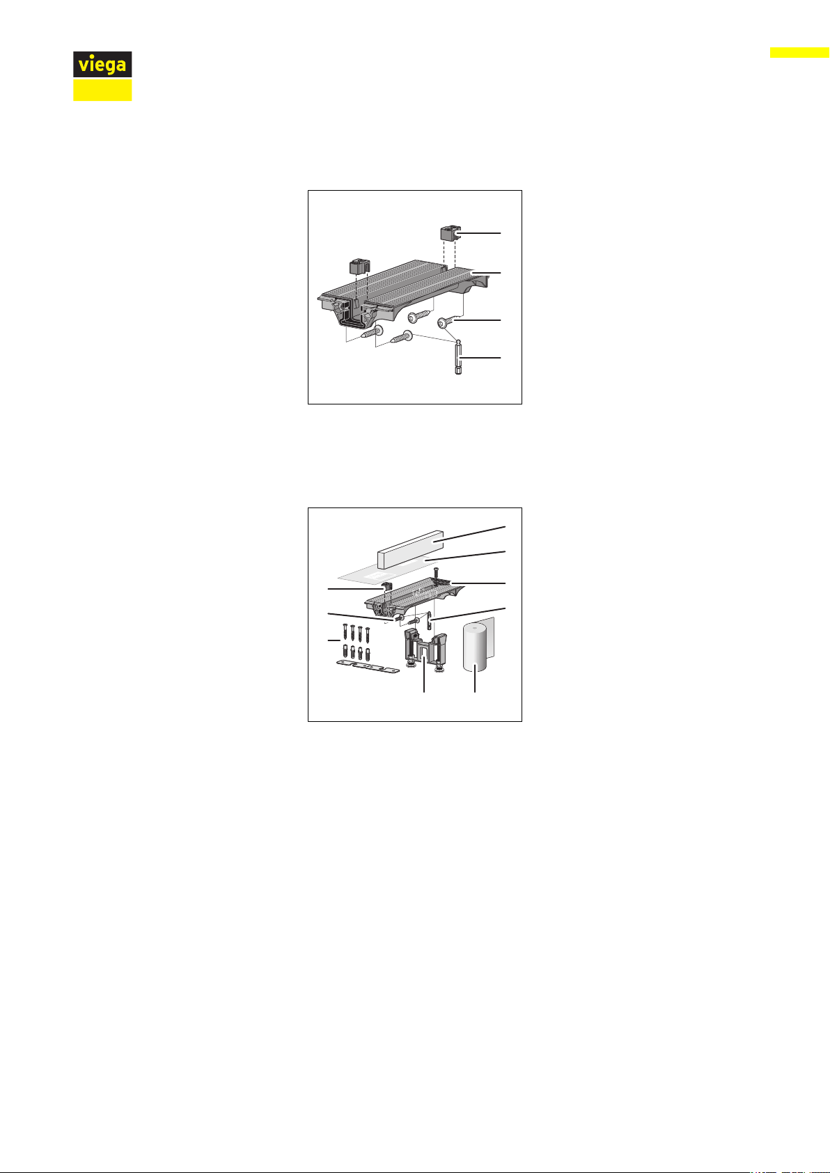
Fig. 7: connection piece, scope of delivery
1 spacer
2 connection piece
3 screws
4 Allen key size 4
Fig. 8: end closing piece, scope of delivery
1 protective insert made of hard foam
2 protective foil
3 end closing piece
4 Allen key size 4
5 sealing tape
6 foot, height-adjustable
7 fixing material
8 screws
9 spacer
Advantix Vario base unit, for Advantix Vario shower channel, can be cut to length continuously 14 from 50
Page 15
1
2
3
4
7
6
5
89
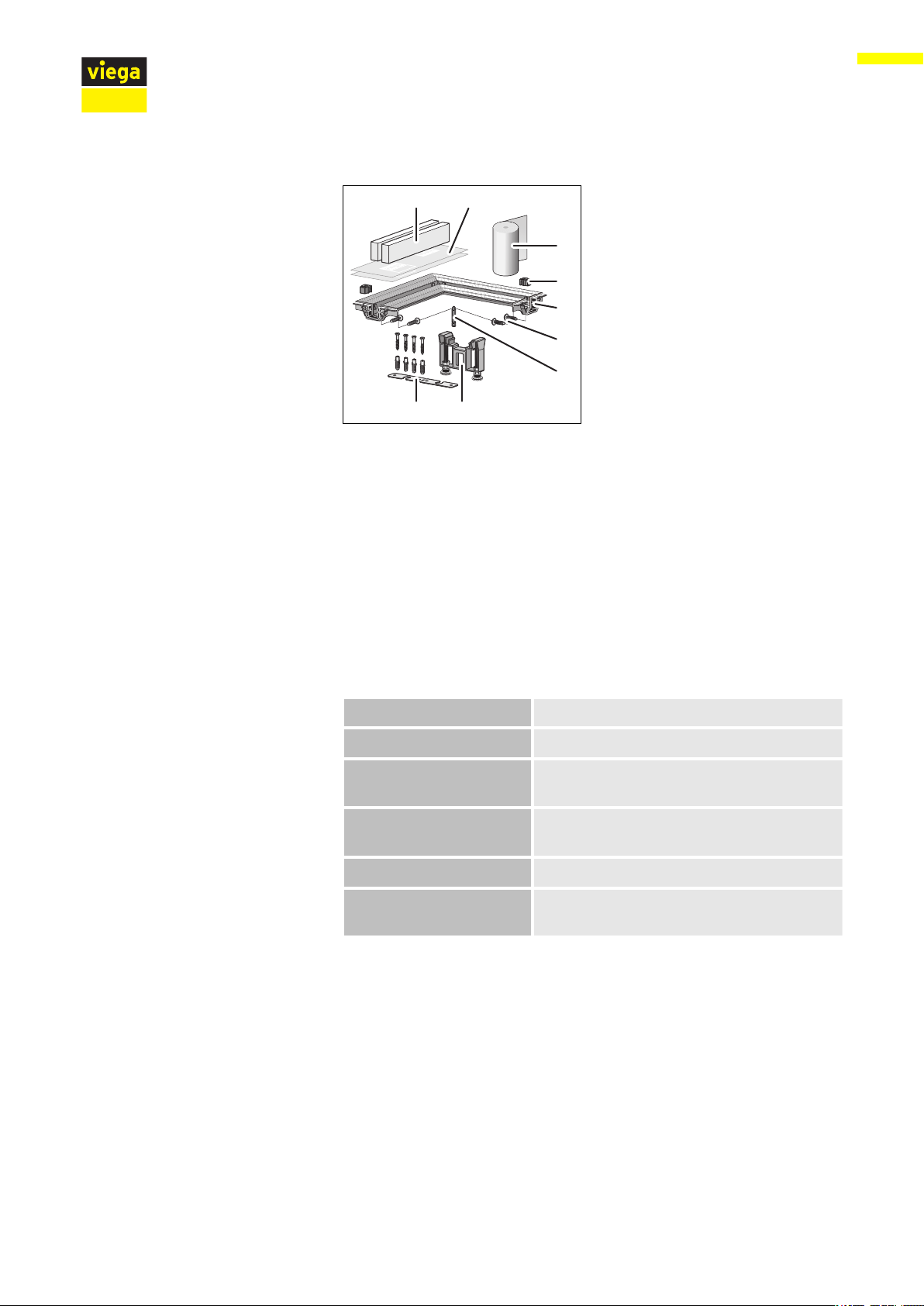
Fig. 9: connection piece 90°, scope of delivery
1 protective insert made of hard foam
2 protective foil
3 sealing tape
4 spacer
5 connection piece 90°
6 screws
7 Allen key size 4
8 foot, height-adjustable
9 fixing material
Product information
2.3.3 Technical data
2.3.4 Sound protection
Nominal width [DN] 40 / 50
Material Base unit made of plastic
Drainage capacity
Ä
Chapter 2.2.3 „Drainage capacity“
on page 9
Dimensions and installa‐
tion height
Ä
Chapter 3.1.3 „Installation dimen‐
sions“ on page 20
Water seal level 50 mm
Load max. 120 kg load per standing grate
bracket
The measured sound level during water drainage is 19 dB(A). For infor‐
mation on sound protection requirements met, see Ä „Regulations from
section: Sound protection“ on page 8.
Advantix Vario base unit, for Advantix Vario shower channel, can be cut to length continuously 15 from 50
Page 16
2.4 Information for use
2.4.1 Sealing
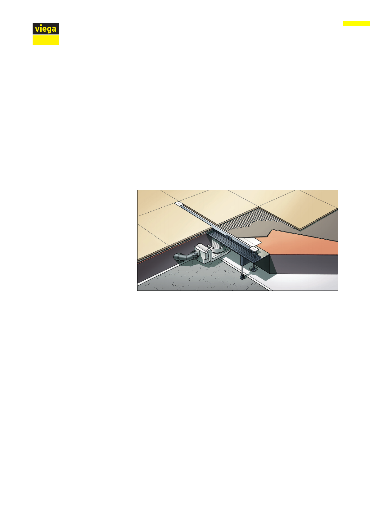
Bonded sealing
Product information
To protect against moisture penetration, apply sealing foils, which are to
be processed in liquid state, directly below the tiles on screed and
walls. The determination of the stress class and the underground as well
as the selection of the suitable bonded sealing must be carried out in
compliance with the valid standards and regulations, see: Ä „Regula‐
tions from section: Sealing“ on page 7.
Fig. 10: Diagram of a bonded seal
Advantix Vario base unit, for Advantix Vario shower channel, can be cut to length continuously 16 from 50
Page 17
1-2%
1 2 43 5
8 67
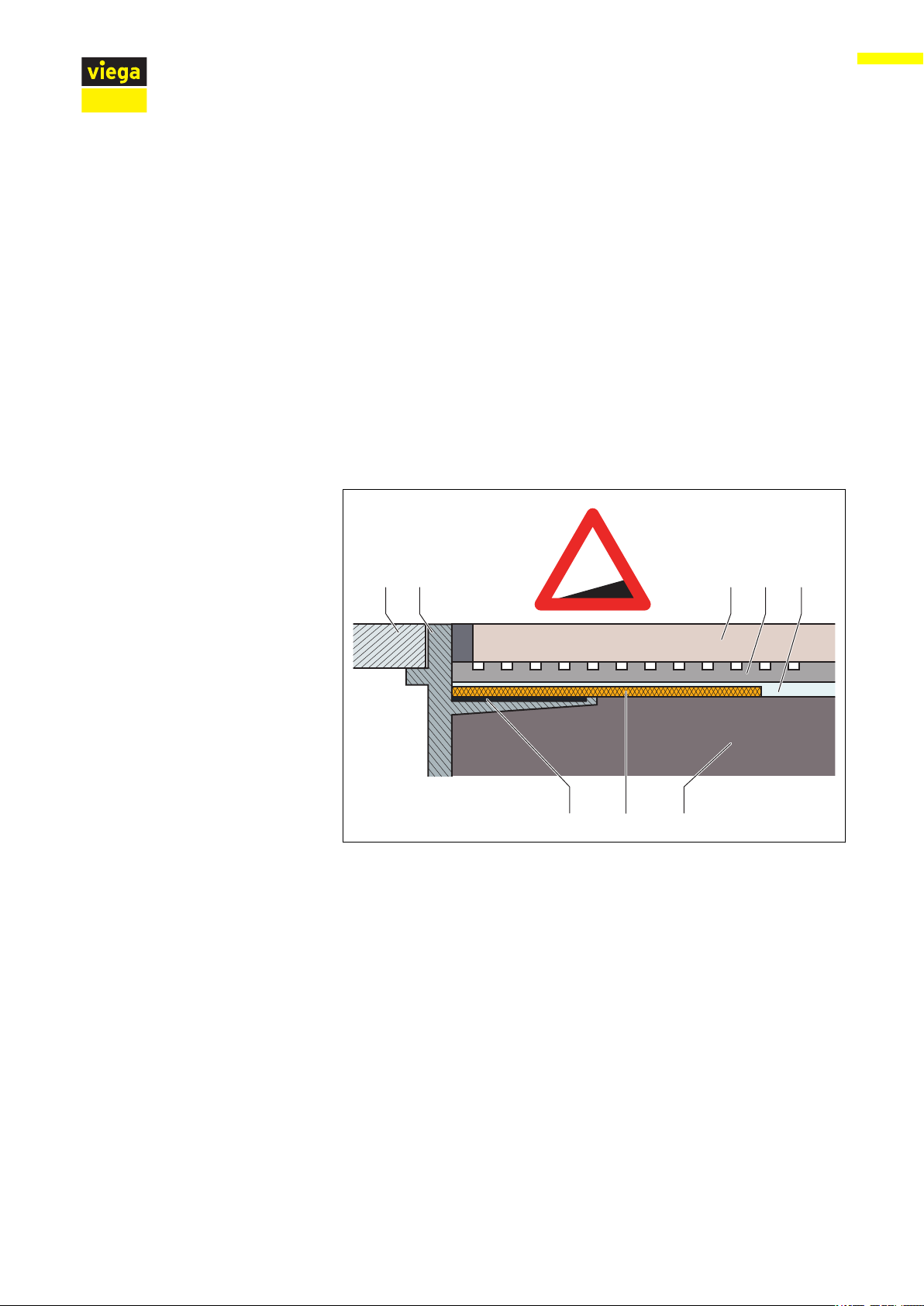
Important note
Product information
Careful planning is required for professional sealing. In addition,
depending on the individual dampness wear class and the type of foun‐
dation, a suitable thin bed sealing with a building regulations certificate
of suitability must be chosen.
Furthermore, the following factors should be taken into account:
n Drain or shower channel must be equipped with a special flange,
which has an adhesive surface and a width of at least 30 mm.
n For bridging the material change from drain to screed, either a suit‐
able sealing collar or sealing tape designed for overlapping with the
thin bed sealing over a width of at least 50 mm must be used.
n The screed must be laid at a minimum incline of 1–2 %.
n The installation must be carried out properly in acc. with the
mounting instructions and the manufacturer's information.
Fig. 11: Construction diagram of the bonded seal - min. screed incline 1–2 %
1 Grate
2 Top piece with adhesive flange
3 Tile
4 Tile cement
5 Bonded sealing
6 Screed
7 sealing collar
8 adhesive
Permitted bonded seals
In connection with suitable drains, only approved bonded sealings with
proof of practicability in keeping with building law may be used. See
Ä
„Regulations from section: Sealing“ on page 7.
Information regarding the procedure can be found in the instructions for
use of the corresponding product.
Advantix Vario base unit, for Advantix Vario shower channel, can be cut to length continuously 17 from 50
Page 18
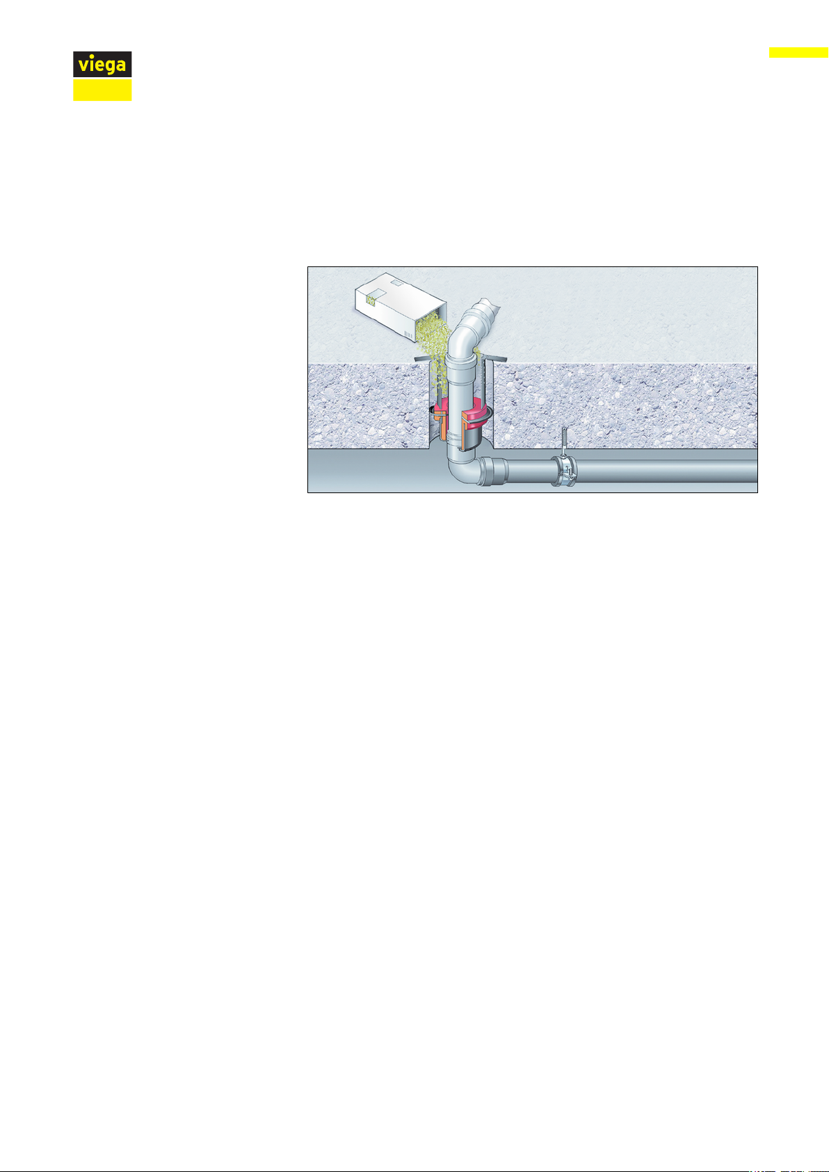
2.4.2 Fire protection
Product information
Advantix shower channels and drains can both be fitted to be fire proof.
The R120 pipe lead-in can be used for this purpose in the floor con‐
struction. In this way, a fire resistance time of up to 120 minutes can be
achieved.
2.5
Fig. 12: Example: fire protection pipe lead-in
Mounting instruction of the R120 pipe lead-in see model 4923.5,
Art.-No. 491 673.
Required accessories
If the basic model of the Vario shower channel is extended by additional
components, the following accessories are required for the mounting of
these components.
Per installed component one corresponding standing grate set and one
accessory set is required. The complete range and the required infor‐
mation can be found in the catalogue.
Advantix Vario base unit, for Advantix Vario shower channel, can be cut to length continuously 18 from 50
Page 19

3 Handling
3.1 Assembly information
3.1.1 Important note
Before assembly:
n Check if the drainage capacity of the model chosen is sufficient for
n In the case of the connection of two or three shower channels:
n An adequate level of floor covering stability must be guaranteed
n The dimensions of slots and recesses must be in compliance with
Handling
the arising water volume Ä Chapter 2.2.3 „Drainage capacity“
on page 9.
Observe the information for dimensioning of collective
lines Ä Chapter 2.2.3 „Drainage capacity“ on page 9.
Ä
Chapter 2.3.3 „Technical data“ on page 15. This can be achieved
either through an adequate covering of screed or another alternative
solution. Relevant measures must be considered before mounting.
Ä
the regulations from section
notes“ on page 8.
„Regulations from section: Important
3.1.2 Tools and materials
Special tools
During assembly:
n Observe installation dimensions.
n For barrier-free showers:
Position the shower channel in such a way that wheelchair wheels
can only cross it at right angles. Viega recommends mounting the
shower channel as close to the wall as possible.
n Do not use mounting adhesive older than 18 months.
n Position the shower channel in such a way that the grate is remov‐
able.
After assembly:
n The shower channel must be fully lined with mortar.
n The sealing accessories should be given to the person responsible
for the bonded sealing (e. g. tiler).
n Coordinate all relevant installation details, especially regarding the
bonded sealing, with those responsible for the subsequent work.
n Spanner size 13
n Hand saw (saw blade maximum 1.5 mm)
n An Allen key in each of the sizes 2.5 and 3
n Drill, 6 mm
n Tool for the removal of the grate (e. g. model 4965.90,
art. no. 689 704)
Advantix Vario base unit, for Advantix Vario shower channel, can be cut to length continuously 19 from 50
Page 20

Mounting adhesive
Fig. 13: Filling date of the mounting adhesive
Handling
Mounting adhesive can be used for a maximum of 18 months.
The filling date is found on the top edge of the cartridge. The first two
numbers represent the month, the following number the year.
Example
085...
Filling date = August (08) 2015 (5)
3.1.3 Installation dimensions
Shower channel, basic model with one base unit
Fig. 14: Dimensions of base unit basic model
Advantix Vario base unit, for Advantix Vario shower channel, can be cut to length continuously 20 from 50
Page 21

10
33
110
210
10
33
110
275
10
33
245
290
110
245
290
110
Connection piece
Handling
Fig. 15: Dimensions of connection piece
end closing piece
connection piece 90°
Fig. 16: Dimensions of end closing piece
Fig. 17: Dimensions of connection piece 90°
Advantix Vario base unit, for Advantix Vario shower channel, can be cut to length continuously 21 from 50
Page 22

3.1.4 Recommended procedure
The variable installation possibilities of the Advantix Vario require careful
planning of the assembly steps. Viega generally recommends the fol‐
lowing order:
1. Calculate length and cut profile to length if necessary.
2. Pre-mount all short profile parts.
3. Connect the pre-mounted parts to the desired shape.
4. Calculate height and mount feet.
5. Mount base unit and align shower channel.
6. Line the shower channel with screed and seal.
7. Tile the floor.
8. Mount the standing grate.
Handling
Description of the assembly steps, see
on page 22.
3.2
Assembly
3.2.1 Calculating the profile length in niche installation
When fitting a shower channel in a niche, the correct size of niche is of
importance so that it will be possible to remove the grate. The exact
profile length must be calculated for this. The base unit without closing
caps is taken as the profile length.
Ä
Chapter 3.2 „Assembly“
Advantix Vario base unit, for Advantix Vario shower channel, can be cut to length continuously 22 from 50
Page 23

Handling
Example
Fig. 18: Niche dimensions
A = Minimum width of the niche from plaster to plaster
B = Minimum width of the niche from tile to tile
The basis of the calculation for the length of the profile is the shower
niche after plastering (see dimension A).
The length of the closing caps is subtracted from this measurement.
The result is the profile length.
1030 mm (plastered shower niche)
−
100 mm (2 closing caps 50 mm each)
=
930 mm (profile length)
Advantix Vario base unit, for Advantix Vario shower channel, can be cut to length continuously 23 from 50
Page 24

3.2.2 Shortening the profile
150
Handling
– If two Vario shower channels are to be joined together,
one of the base units must be shortened by at least
210 mm Ä Chapter 3.2.2 „Shortening the profile“
on page 23.
– End closing pieces, connection pieces and connection
pieces 90° must not be shortened.
Calculate profile length, also see Ä Chapter 3.2.1 „Calculating the
profile length in niche installation“ on page 22.
Transfer the length of the profile onto the shower channel.
INFO! Depending on the installation situation, the shower
channel can be shortened on one or both sides. The position
of the drain may be chosen freely. However, the distance
from the middle of the drain to the end of the profile may not
be less than 150 mm.
Shorten the profile with a hacksaw.
The saw blade must not be wider than 1.5 mm.
Advantix Vario base unit, for Advantix Vario shower channel, can be cut to length continuously 24 from 50
Page 25

Handling
Carefully deburr all edges.
Particular attention should be paid to surfaces in contact with the
seal.
The profile must be lubricated in the area around the seal.
INFO! No lubricant should come into contact with the flange!
Optimal adhesion of the sealing material is only ensured on a
grease-free flange.
If necessary, clean flange. Use the cleaning cloth supplied or a nongreasing cleaner, e. g. isopropanol.
You now have various possibilities:
n Mount closing caps and base unit. Ä Chapter 3.2.3 „Mounting the
closing caps on base unit“ on page 26
n Mount extending parts. Ä Chapter 3.2.4 „Pre-mounting extending
parts“ on page 26
Advantix Vario base unit, for Advantix Vario shower channel, can be cut to length continuously 25 from 50
Page 26

3.2.3 Mounting the closing caps on base unit
M 3 Nm
≤
A
Screw the closing cap onto the profile straight.
When using a cordless screwdriver, make the last few turns by
hand.
Only tighten screws hand-tight!
The closing cap is properly mounted when the seal is pushed
ð
together gently.
Handling
You must now calculate the height and align the shower channel
Ä
Chapter 3.2.5 „Determine height“ on page 30.
3.2.4 Pre-mounting extending parts
To start with, all short profile parts should pre-mounted. Then the premounted units are connected to the base unit.
NOTICE!
Risk of breakage when lifting
Do not lift or turn pre-mounted units on one side.
– In the case of L and U designs, lift the sides at the same
time.
Advantix Vario base unit, for Advantix Vario shower channel, can be cut to length continuously 26 from 50
Page 27

Mounting the end closing piece
M 3 Nm
A
4
≤
Screw the end closing piece onto the profile.
When using a cordless screwdriver, make the last few turns by
hand.
Only tighten screws hand-tight!
The end closing piece is properly mounted when the seal is
ð
pushed together gently.
Handling
Advantix Vario base unit, for Advantix Vario shower channel, can be cut to length continuously 27 from 50
Page 28

Mounting the connection piece
4
M 3 Nm≤
A
Screw the connection piece onto the profile straight.
When using a cordless screwdriver, make the last few turns by
hand.
Only tighten screws hand-tight!
The connection piece is properly mounted when the seal is
ð
pushed together gently.
Handling
Advantix Vario base unit, for Advantix Vario shower channel, can be cut to length continuously 28 from 50
Page 29

Mounting the connection piece 90°
4
M 3 Nm≤
A
Screw the connection piece 90° onto the profile straight.
When using a cordless screwdriver, make the last few turns by
hand.
Only tighten screws hand-tight!
The connection piece 90° is properly mounted when the seal
ð
is pushed together gently.
Handling
Advantix Vario base unit, for Advantix Vario shower channel, can be cut to length continuously 29 from 50
Page 30

3.2.5 Determine height
1
2
Handling
Determine screed height (H).
The max installation height is 165 mm.
Shorten the height adjustment piece by dimension H.
Deburr height adjustment piece.
Mount seal (1) and both O-rings (2).
Advantix Vario base unit, for Advantix Vario shower channel, can be cut to length continuously 30 from 50
Page 31

Lubricate seal and O-rings.
Place the height adjustment piece into the drain.
Handling
3.2.6 Mounting feet and drain socket
If two Vario-shower channels are connected to one another,
one of the base units must be shortened by at least 210 mm
Ä
Chapter 3.2.2 „Shortening the profile“ on page 24.
Advantix Vario base unit, for Advantix Vario shower channel, can be cut to length continuously 31 from 50
Page 32
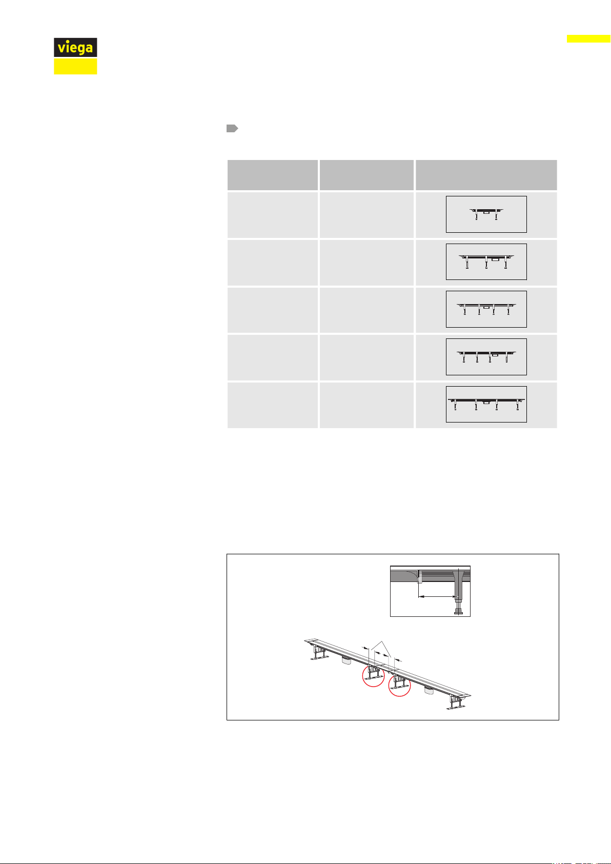
Calculate the number of feet required using the table.
max. 100 mm
max. 100 mm
Handling
Length of the
Number of feet Spacing
shower channel
30–60 cm 2
60–90 cm 3
60–90 cm 4
90–120 cm 4
90–120 cm 4
The following applies for mounting the feet:
n The maximum permissible distance between two feet is 400 mm.
n The maximum permissible distance between a foot and a fixing point
of two parts is 100 mm.
A fixing point is the point where two components are screwed
together.
n During the mounting of connection pieces 90°:
An additional foot must be mounted below the corner angle
Fig. 19: distance between fixing point and foot = maximum 100 mm
Advantix Vario base unit, for Advantix Vario shower channel, can be cut to length continuously 32 from 50
Page 33

Handling
Fig. 20: when using the connection piece 90°, an additional foot must be mounted below the
corner
Position the foot and push the profile into place.
Insert the drain socket
WARNING! Risk of breakage when lifting Do not lift or turn the
shower channel on one side.
– In the case of L and U designs, lift the sides at the same time.
Push the shower channel with the drain socket into the height
adjustment piece as far as it will go.
Advantix Vario base unit, for Advantix Vario shower channel, can be cut to length continuously 33 from 50
Page 34

3.2.7 Aligning and connecting
Aligning and connecting the base unit
Handling
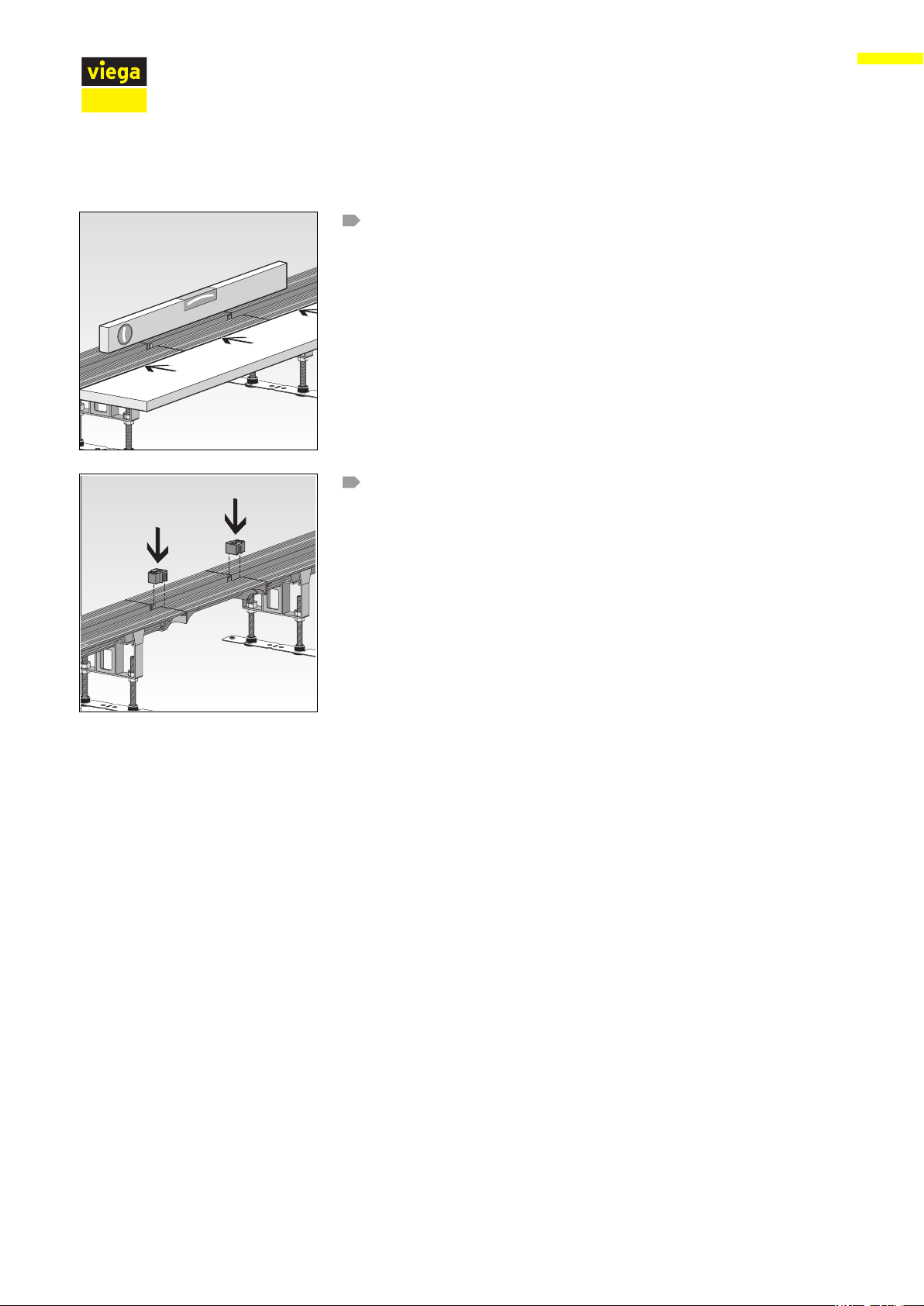
Check whether the shower channel is inserted as far as it will go.
The water that occurs must be discharged properly. If
required, multiple drains and suitably dimensioned drain‐
pipes must be installed Ä Chapter 2.2.3 „Drainage
capacity“ on page 9.
Align shower channel horizontally.
The water can then drain away well.
Fix the foot height adjustment with lock nuts.
Connect the drain to the wastewater system.
Secure the feet in place with fixing material if necessary.
Advantix Vario base unit, for Advantix Vario shower channel, can be cut to length continuously 34 from 50
Page 35

Aligning the end closing piece
Handling
Align the shower channel and connection piece horizontally to one
another.
Insert spacer.
The spacers prevent the shower channel from being deformed when
the screed hardens later.
Advantix Vario base unit, for Advantix Vario shower channel, can be cut to length continuously 35 from 50
Page 36
Aligning the connection piece
Handling
Align the shower channel and connection piece horizontally to one
another.
Insert spacer.
The spacers prevent the shower channel from being deformed when
the screed hardens later.
Advantix Vario base unit, for Advantix Vario shower channel, can be cut to length continuously 36 from 50
Page 37

Aligning the connection piece 90°
90°
Handling
Align shower channel and connection piece 90° both horizontally
and perpendicular to one another.
Insert spacer.
The spacers prevent the shower channel from being deformed when
the screed hardens later.
Advantix Vario base unit, for Advantix Vario shower channel, can be cut to length continuously 37 from 50
Page 38

3.2.8 Preparing for further work
Handling
Fill shower channel with water.
Check drain casing and pipe for leaks.
Insert the test adapter into the drain opening of the shower channel.
Fill the shower channel up to just below the flange with water.
Check the end closing pieces for leaks.
If necessary, shorten the protective foil and stick onto the flange.
Completely cover the closing caps with protective foil.
Advantix Vario base unit, for Advantix Vario shower channel, can be cut to length continuously 38 from 50
Page 39
Lining with screed
Handling
NOTICE!
Product damage due to improper installation
If hollow spaces occur during the lining of the shower
channel, leaks may occur when pressure is applied.
Inform the subsequent workers that the shower channel
must be fully lined and that there must be no hollow spaces.
Requirements:
n The flange must be coated with protective foil.
INFO! Screed and floor tiles must be laid at an incline of 1–2 % in
the direction of the shower channel.
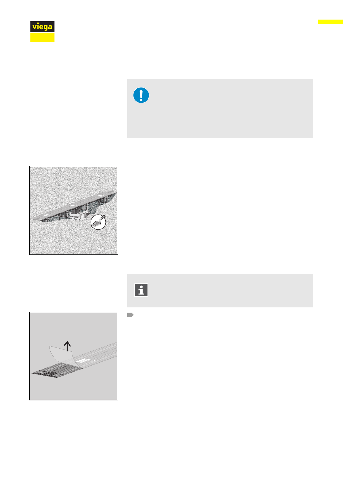
3.2.9 Sealing the shower channel
Remove protective foil.
Screed and floor tiles must be laid at an incline of 1–2 % in
the direction of the shower channel.
Advantix Vario base unit, for Advantix Vario shower channel, can be cut to length continuously 39 from 50
Page 40

Handling
When using extension pieces:
Remove spacer.
If necessary, clean flange.
Use the cleaning cloth supplied or a non-greasing cleaner, e. g. iso‐
propanol.
Cut protective insert to size and insert.
Cut the sealing tape strips generously.
The strips should overlap when stuck on.
Advantix Vario base unit, for Advantix Vario shower channel, can be cut to length continuously 40 from 50
Page 41
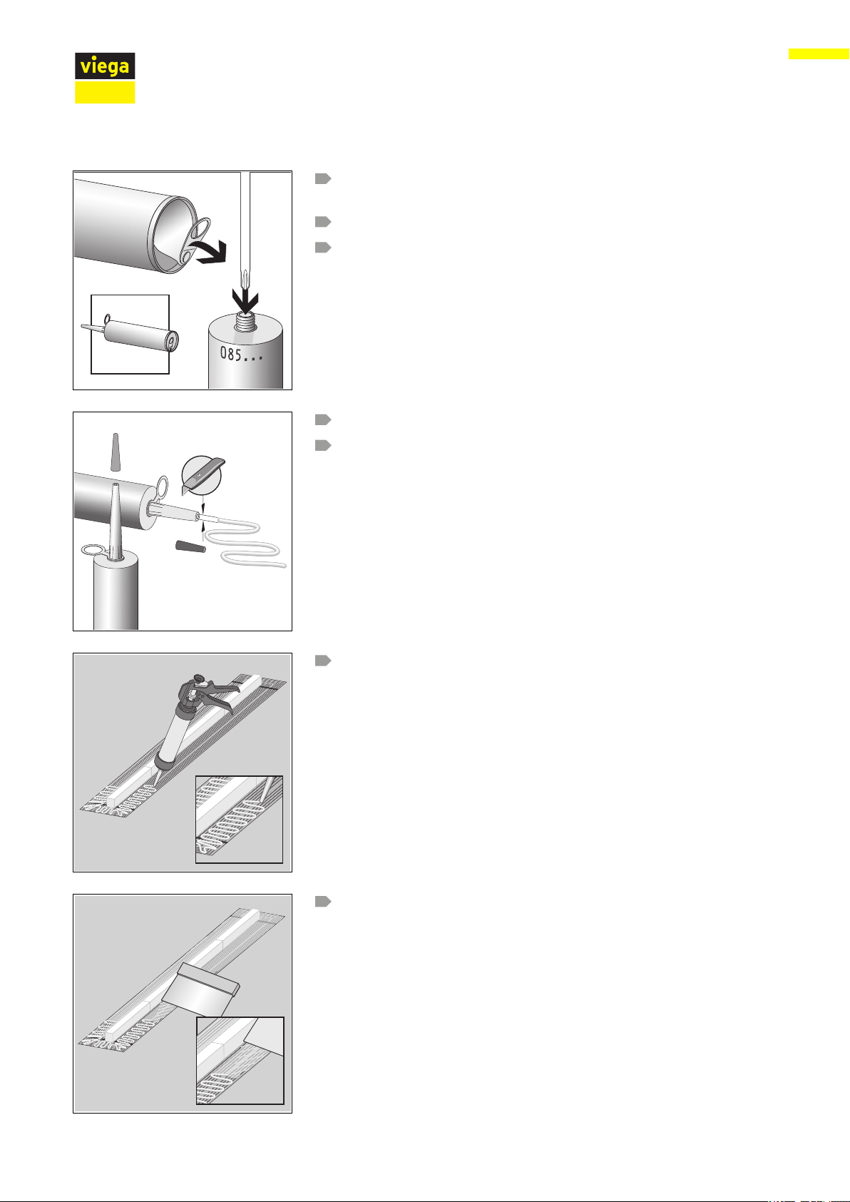
Check the expiry date on the cartridge, see Ä „Mounting adhe‐
ca. 8 mm
sive“ on page 20.
Open the aluminium cover at the end of the cartridge, and lift.
Fully pierce the membrane in the thread of the cartridge.
Screw the nozzle on.
Cut the nozzle so that the opening is approx. 8 mm wide.
Handling
Apply mounting adhesive in curves.
Observe the shelf life of the mounting adhesive, see Ä „Mounting
adhesive“ on page 20.
Distribute the mounting adhesive evenly using a smooth spatula.
Advantix Vario base unit, for Advantix Vario shower channel, can be cut to length continuously 41 from 50
Page 42

Handling
Apply the first layer of bonded sealing generously onto the screed.
Observe the bonded sealing manufacturer's instructions for use.
Press the sealing tape firmly onto the mounting adhesive and
bonded sealing.
In doing so, leave approx. 10 mm to the protective insert uncovered.
Position the sealing tape on the flange so that the flange and screed
are uniformly covered.
Overlap the corners in the process.
Stick the overlapping strips together at the corners with mounting
adhesive.
Rework the sticking points with a roller.
Let the adhesive dry for approx. 4 hours.
Apply the second layer of bonded sealing generously onto the
sealing tape and floor screed.
If no cover trim is to be fitted, the floor can be tiled.
Further see Ä „Mounting without cover trim rail“ on page 44.
Advantix Vario base unit, for Advantix Vario shower channel, can be cut to length continuously 42 from 50
Page 43

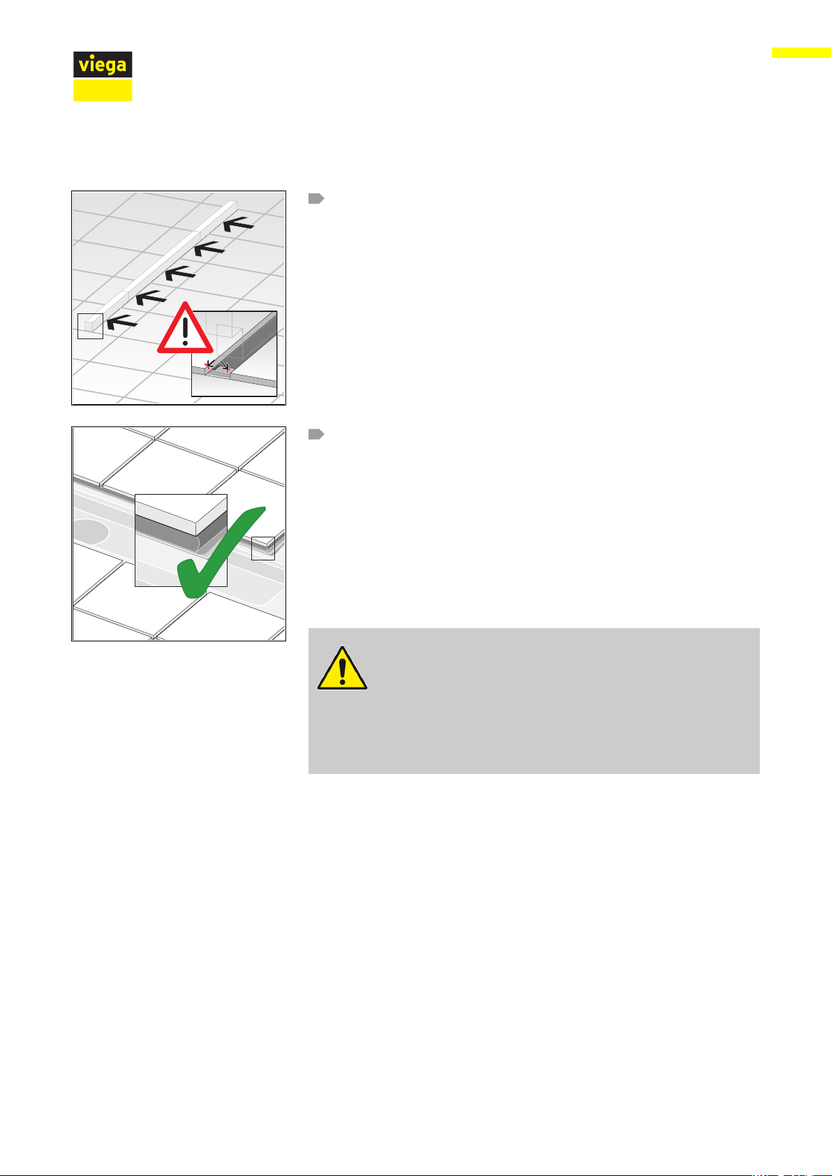
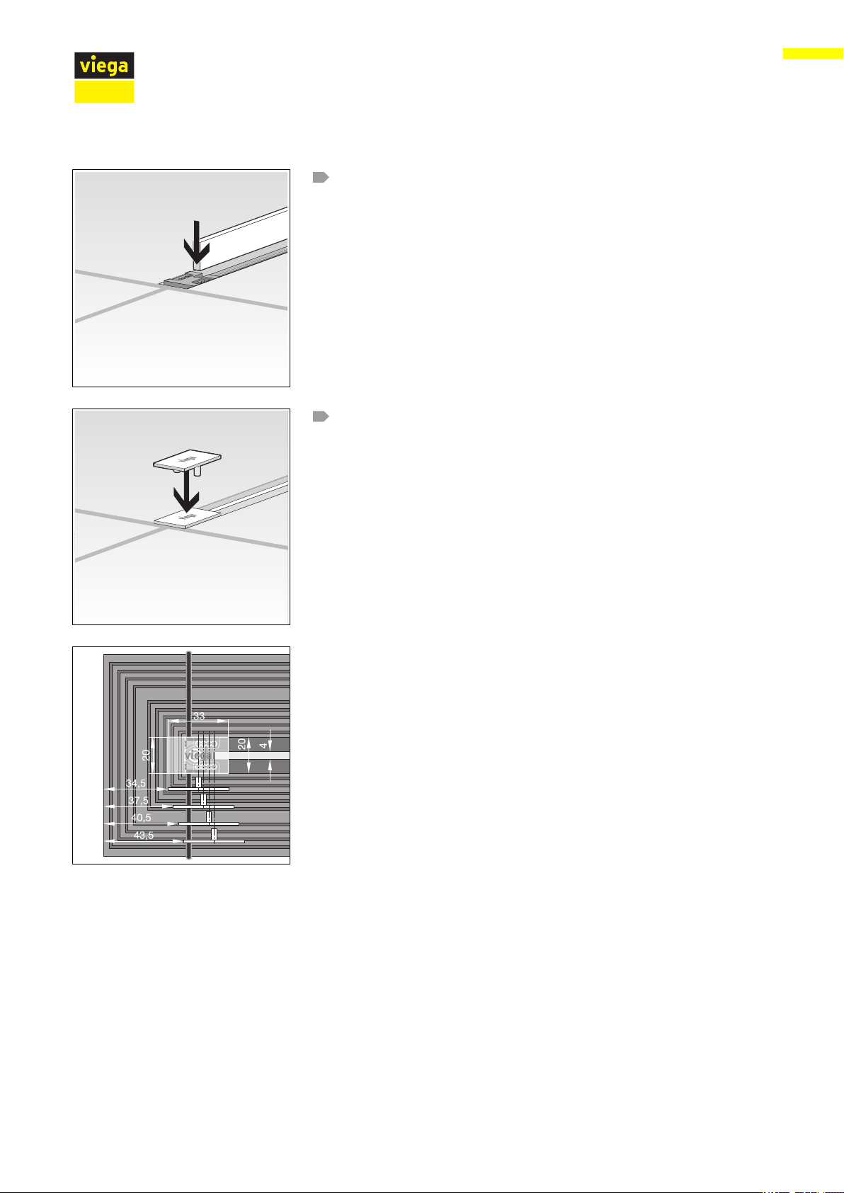
Mounting with cover trim rail
Handling
Stick the profile in a straight line on the insert.
The rail must be closed with the protective insert at both ends.
Deburr edges that were cut.
Avoid differences in height between different parts of the strip.
You have installed the shower channel.
ð
The floor can now be tiled.
Further see Ä „Mounting without cover trim rail“ on page 44.
Advantix Vario base unit, for Advantix Vario shower channel, can be cut to length continuously 43 from 50
Page 44
Mounting without cover trim rail
Handling
Stick the tiles right up to the protective insert.
Connect the tile edge onto the channel side with tile cement or joint
filler.
Thus no water can get under the floor covering during showering.
INFO! To ensure that penetrating dampness in the channel
area can dry off, the joint edges must be sealed with tile
adhesive or joint filler. This is of particular relevance when
there is a large number of joints, e. g. with mosaic tiles.
The shower channel is installed and the tile edge can be pol‐
ð
ished.
CAUTION!
Avoid sharp edges in the following places in the barefoot
area:
– on tiles
– on cover trims
– on cover trim profiles
Optionally, you can now insert the sieve, see Ä Chapter 3.2.10
„Inserting the sieve“ on page 45.
Finally, a standing grate must be mounted, see Ä Chapter 3.2.11
„Mounting the standing grate“ on page 45. See the catalogue for suit‐
able standing grates.
Advantix Vario base unit, for Advantix Vario shower channel, can be cut to length continuously 44 from 50
Page 45

3.2.10 Inserting the sieve
Handling
Optionally, a sieve can be inserted. When using the sieve, the drainage
capacity drops by 0.05 l/s per drain.
Remove protective insert.
Insert the sieve above the drain in the channel gap.
To finish with, a standing grate must be mounted.
3.2.11 Mounting the standing grate
Note regarding accessories
The total length of the shower channel increases if the basic model of
the Vario shower channel is extended with other parts. In this case, the
relevant accessory must be mounted for every extra part.
Advantix Vario base unit, for Advantix Vario shower channel, can be cut to length continuously 45 from 50
Page 46

Assembly steps
Handling
With natural stone covering, observe the correct height and
use the mounting material from the accessory set for natural
stone covering.
Remove protective insert.
Insert screws.
Place the grate holder onto the screw and adjust to tile height.
The maximum height of the standing grate is 20 mm above the
flange.
When using the natural stone set, the maximum height of the
standing grate is 30 mm above the flange.
Advantix Vario base unit, for Advantix Vario shower channel, can be cut to length continuously 46 from 50
Page 47

Handling
The upper edge of the grate holder must be approx. 1 mm below the
upper edge of the tiles.
Determine the length of the standing grate.
INFO! Use the standing grate with a length of 200 mm for end
closing pieces and connection pieces 90°.
If required, shorten the standing grate with a handsaw and deburr.
Do not use a circular saw or angle grinder.
INFO! The standing grate with a length of 200 mm must not
be shortened!
Secure the grate supports to the standing grate.
Distribute the standing grate supports in such a way that there is a
grate support fitted after every one third of the grate.
Advantix Vario base unit, for Advantix Vario shower channel, can be cut to length continuously 47 from 50
Page 48
Insert the standing grate.
Replace cover caps.
Handling
3.3
Care
3.3.1 Care tips
The cover caps can be moved by up to 9 mm (see fig,).
Normal soap or a mild cleaning agent can be used for regular mainte‐
nance and prevention of lime scale on the grate and frame. Use no
scouring agent or abrasive objects.
Strong stains, even around the drain unit and the siphon, can be
removed using typical household cleaner. Rinse the detergent very thor‐
oughly with clear water after the prescribed dwell time. There should be
no residue on the components.
Advantix Vario base unit, for Advantix Vario shower channel, can be cut to length continuously 48 from 50
Page 49

3.3.2 Cleaning
Handling
Viega recommends using a mild cleaning agent, a cloth and a washingup brush for cleaning.
Remove cover caps and standing grate.
If applicable, remove sieve.
Insert cleaning device.
Place the plunger onto the cleaning device and clean the shower
channel.
Remove the cleaning device.
Remove the standing grate.
Replace cover caps.
Advantix Vario base unit, for Advantix Vario shower channel, can be cut to length continuously 49 from 50
Page 50

3.4 Disposal
Handling
Separate the product and packaging materials (e. g. paper, metal,
plastic or non-ferrous metals) and dispose of in accordance with valid
national legal requirements.
Advantix Vario base unit, for Advantix Vario shower channel, can be cut to length continuously 50 from 50
 Loading...