

Page 1
BMS module binary
Instructions for Use
For flushing stations with Viega Hygiene+ function
Model Year built:
2241.68 from 11/2017
en_INT
Page 2

BMS module binary 2 from 12
Page 3
Table of contents
1 About these instructions for use 4
Table of contents
1.1
1.2
1.3
Target groups 4
Labelling of notes 4
About this translated version 5
2 Product information 6
2.1
2.1.1
2.2
2.2.1
2.2.2
Intended use 6
Areas of use of the BMS module 6
Product description 6
Overview 6
Technical data 7
3 Handling 8
3.1
3.1.1
3.2
3.2.1
3.2.2
3.2.3
3.3
3.3.1
3.4
Assembly information 8
Required material and tools 8
Assembly 8
Mounting the BMS module on the basic holder system 8
Mounting and connecting the BMS module 10
Switching on 11
Commissioning 11
Commissioning the BMS module in a new system 11
Disposal 12
BMS module binary 3 from 12
Page 4
About these instructions for use
1 About these instructions for use
Trade mark rights exist for this document; for further information, go to
viega.com/legal.
1.1 Target groups
The information in this instruction manual is directed at the following
groups of people:
n Heating and sanitary professionals and trained personnel
n Qualified electricians
n Operators
Individuals without the abovementioned training or qualification are not
permitted to mount, install and, if required, maintain this product. This
restriction does not extend to possible operating instructions.
1.2
The installation of Viega products must take place in accordance with
the general rules of engineering and the Viega instructions for use.
Labelling of notes
Warning and advisory texts are set aside from the remainder of the text
and are labelled with the relevant pictographs.
DANGER!
This symbol warns against possible life-threatening injury.
WARNING!
This symbol warns against possible serious injury.
CAUTION!
This symbol warns against possible injury.
NOTICE!
This symbol warns against possible damage to property.
Notes give you additional helpful tips.
BMS module binary 4 from 12
Page 5

1.3 About this translated version
This instruction for use contains important information about the choice
of product or system, assembly and commissioning as well as intended
use and, if required, maintenance measures. The information about the
products, their properties and application technology are based on the
current standards in Europe (e. g. EN) and/or in Germany
(e. g. DIN/DVGW).
Some passages in the text may refer to technical codes in Europe/
Germany. These should serve as recommendations in the absence of
corresponding national regulations. The relevant national laws, stand‐
ards, regulations, directives and other technical provisions take priority
over the German/European directives specified in this manual: The
information herein is not binding for other countries and regions; as said
above, they should be understood as a recommendation.
About these instructions for use
BMS module binary 5 from 12
Page 6

2 Product information
2.1 Intended use
2.1.1 Areas of use of the BMS module
The BMS module 2241.68 is suitable exclusively for flushing stations
with Viega+ Hygiene function, models 2241.10 and 2241.20.
For detailed installation instructions, refer to the instructions for use for
the flushing station.
2.2 Product description
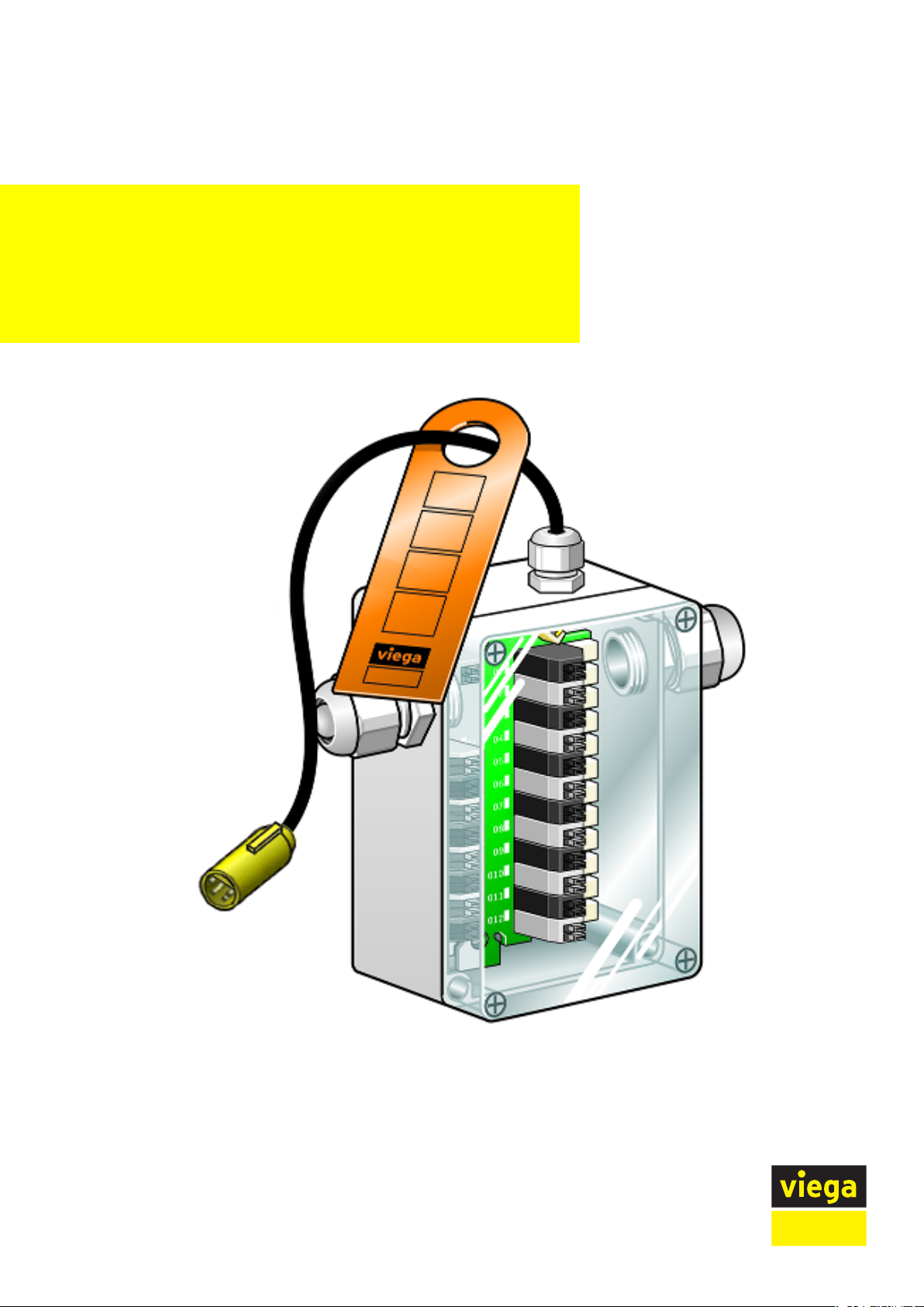
2.2.1 Overview
Product information
Fig. 1: BMS module, overview
BMS module binary 6 from 12
Page 7

2.2.2 Technical data
Model Art. no. Product description
2241.68 739 200 BMS module binary
n For binary communication/connection of
flushing station with Viega Hygiene+ tech‐
nology
n Activation of potential-free working binary
inputs and binary outputs of building auto‐
mation
n connection adapter
n Splash water protected, IP54
n 8 inputs (signals from building automation,
potential-free)
n 12 outputs (signals for building automation,
relay contact max. 24 V / 100 mA)
n Operating status indication through
assigned LED
n Line length to the bus node at 0.5 mm
cable cross-section: max. 25 m
Product information
2
BMS module binary 7 from 12
Page 8

3 Handling
3.1 Assembly information
3.1.1 Required material and tools
Required tools for mounting with self-tapping screws:
n Drill (diameter 3 mm)
3.2 Assembly
3.2.1 Mounting the BMS module on the basic holder system
The eight binary inputs of the BMS module are marked I1 to I8. Addi‐
tionally, the clamp-type terminals are colour-coded alternately. The
twelve binary outputs of the BMS module are marked O1 to O12. Addi‐
tionally, the clamp-type terminals are colour-coded alternately.
Handling
Mounting with adhesive tape
Remove the protective foil from the adhesive tape.
Fasten the BMS module on the basic holder system.
NOTICE! Once glued in, the module cannot easily be
removed. Ensure that the contact areas are dry and free of
dirt and oil.
BMS module binary 8 from 12
Page 9

Mounting with self-tapping
screws
Handling
Mark the positions of the mounting holes.
Drill the mounting holes (bore diameter: 3 mm).
Use the self-tapping screws to fasten the BMS module on the basic
holder system.
BMS module binary 9 from 12
Page 10

3.2.2 Mounting and connecting the BMS module
Unscrew the cable screw connection.
Remove the protective plug.
Handling
Screw the connection on.
Insert the connection cable max. 14 x 2 x 0.8 (single core max.
0.8 mm Ø approx. 0.5 mm2 ).
Tighten the cable screw connection.
BMS module binary 10 from 12
Page 11

3.2.3 Switching on
Handling
Strip 8 mm of the single cores.
Plug the single cores in the respective slot at an angle of approx.
45°.
NOTICE!
Connecting the connection plug to the control too soon will
damage the flushing station.
At this step, do not connect the connection plug to the con‐
trol.
The binary inputs of the BMS module must only be controlled from the
building automation via potential-free NO contacts.
The binary outputs of the BMS module (relay contact / NO contact) con‐
trol the inputs of the building automation potential-free, max.
24 V / 100 mA.
3.3
Commissioning
3.3.1 Commissioning the BMS module in a new system
Commissioning of the flushing station is completed.
n Carry out commissioning of the flushing station, see instructions for
the flushing station.
Put the plug in the yellow socket.
Establish the connection to the control.
Call up the web application.
Activate the BMS module in the configuration menu.
Refresh the page.
The „BMS module“ appears on the left.
ð
BMS module binary 11 from 12
Page 12

3.4 Disposal
Handling
Separate the product and packaging materials (e. g. paper, metal,
plastic or non-ferrous metals) and dispose of in accordance with valid
national legal requirements.
Electronic components and batteries must not be put in the domestic
waste but must be disposed of appropriately in conformity with the
WEEE guideline 2012/19/EU.
BMS module binary 12 from 12
 Loading...