

Page 1
Product Instructions
Digital Thermostat
Applications
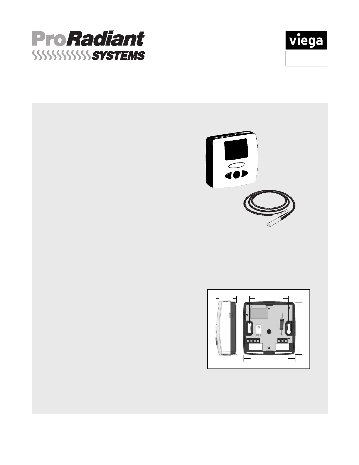
The Digital Thermostat is ideal for individual
room temperature control. A user friendly
three button design allows for easy change
of settings. Thermostat can sense either
room temperature, oor temperature or both.
Adjustable temperature setback function
allows for energy savings. Thermostat can
control up to four Powerheads directly or can
be connected to a zone / circulator control
box. With optional oor sensor, thermostat
provides oor high or low limit function for oor
protection or oor warming.
Features
• Compact design
• Digital LCD display
• Regulates oor or room temperature or both
• Optional Floor Sensor
• Setback function
Specifications
Control:
Accuracy:
Set temperature range:
Environment range:
Power supply:
Output:
Optional oor sensor:
Floor limiting range:
Electrical Protection:
301 N. Main, 9th Floor • Wichita, KS 67202 • Ph: 877-843-4262 • Fax: 800-976-9817 • E-Mail: [email protected] • www.viega.com
PI-PR-18050-0309 (Digital Thermostat)
Microprocessor control
0 . 2 ° F
41 °F - 99 °F, 0.5 °F increments
32 °F - 122 °F
_
24 V +/
TRIAC output 24 VAC, 15 W max
NTC thermistor, (10K Ohms) 10' cable
50 °F - 104°F
Class II - IP30
10% 60Hz 15 W max
Viega... The global leader in plumbing and heating systems.
1.22"
2.36"
3.15"
3.15"
1 of 4
Page 2
Product Instructions
24 VAC
TRANSFORMER
120 VAC
INPUT
WHITE
BLACK
Digital Thermostat
Mounting
Thermostats are typically mounted 48" to 60" from
the sub oor. Thermostats should not be located
in direct sunlight or in areas where solar gain
can occur. Other potential heat emitters are large
electrical gang boxes and dimmer switches. These
give off heat inside the wall and can cause a false
reading. Thermostats should always be located on
an interior wall.
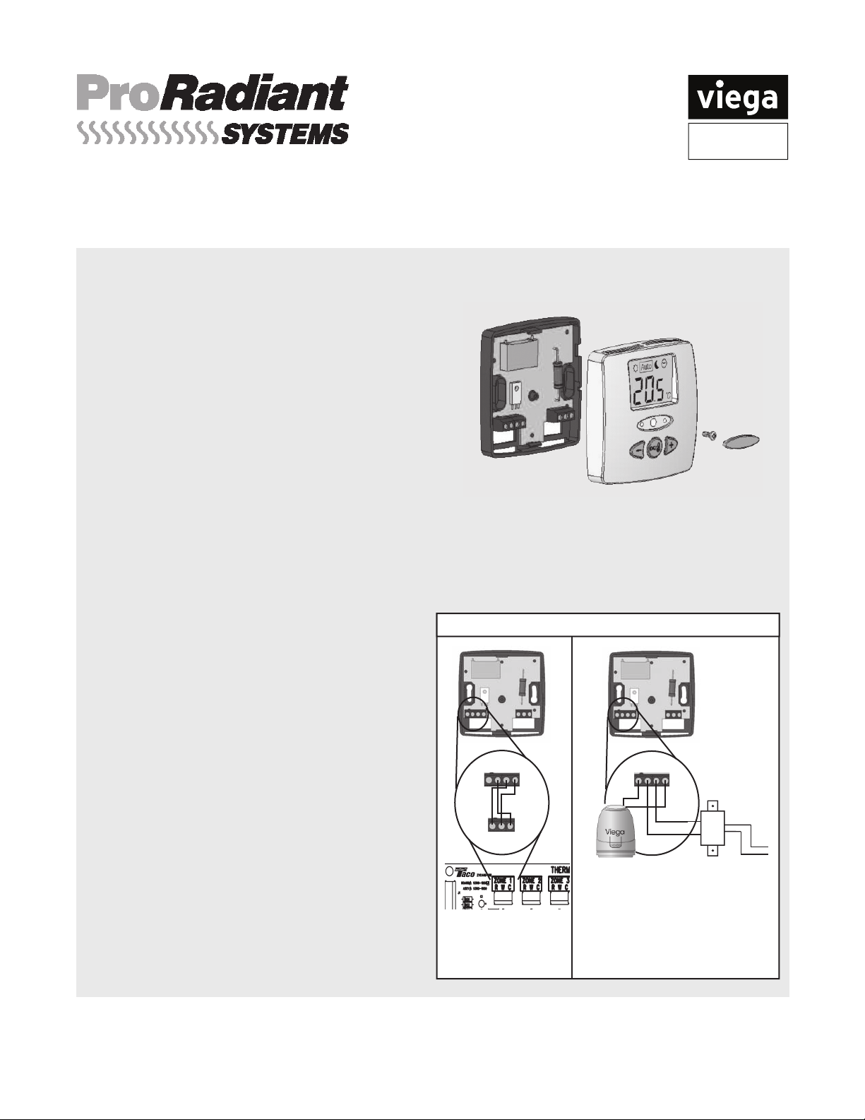
Remove white oval screw cover, located in the
middle of the thermostat. Then remove the #1
phillips screw. Pull the front cover off the black
back plate.
Thermostats have slotted mounting holes
simplifying leveling of the thermostat. Thermostats
should be installed with sleeves and anchors when
mounting into drywall.
Wiring Thermostat to Zone Control
Connect the "R" terminal of the thermostat 1.
Typical Wiring of Digital Thermostats
to the "R" terminal of the Zone Control. "R"
supplies power to the thermostat.
Connect the "W" terminal of the thermostat to 2.
the "W" terminal of the Zone Control. "W" is
the switching signal.
Connect the "C" terminal of the thermostat to 3.
the "C" terminal of the Zone Control. "C" is
common.
(See diagram to right)
C C R W
C C R W
Wiring Thermostat to Powerhead
Connect a "C" and "R" terminals of the 1.
thermostat to transformer.
Connect the other "C" terminal and 2.
"W" terminal of the thermostat to Viega
Powerhead.
Up to 4 powerheads per thermostat may be 3.
connected.
(See diagram to right)
301 N. Main, 9th Floor • Wichita, KS 67202 • Ph: 877-843-4262 • Fax: 800-976-9817 • E-Mail: [email protected] • www.viega.com
PI-PR-18050-0309 (Digital Thermostat)
Viega... The global leader in plumbing and heating systems.
R W C
Digital Thermostat
Connected to a 4 or
6 Zone Control Box
Digital Thermostat with
Transformer and up to 4
Powerheads
2 of 4
Page 3
Product Instructions
Digital Thermostat
Programming
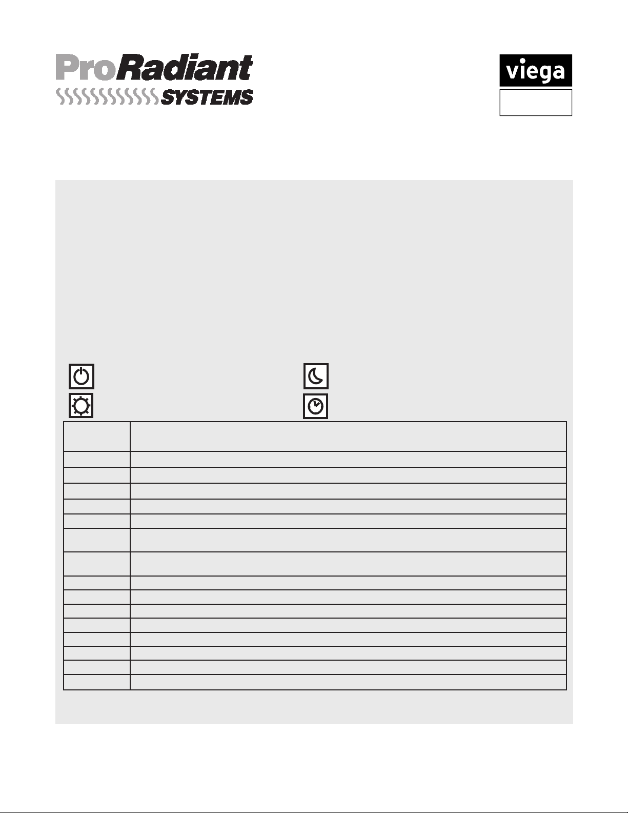
To program the Viega Digital Thermostat, press the "OK" button for 5 continuous seconds until the END
screen appears. Use the "+" or "-" buttons to scroll through the settings. The programming codes are
in the upper right corner of the LCD screen. To adjust any of the default settings press the "OK" button.
The screen will blink. Then use the "+" or "-" buttons to make desired changes. If there are only two
options for the programming code, pressing the "OK" button will cycle through them. If there are multiple
programming options like high limit oor temp (FH), press "OK" button to select, then "+" or "-" buttons to
adjust. Once changes are made, press the "OK" button then continue using the "+" or "-" to scroll through
additional programming options. See chart below.
Operating Mode
Use the "OK" button to scroll through the four Operating Modes
OFF Mode - No power for thermostat.
Screen is blank.
Comfort Mode - Standard, adjust using "+"
or "-" buttons for desired room temperature
Program
Codes
Reduced Temperature Mode - Thermostat
automatically sets back room temperature by 7°
External Clock Mode - Thermostat will follow
external clock signal
Defaults and Options
JO °F or °C temperature display setting
J1 "Hot" or "Cold", Select "Hot" for heating system
Cy* Proportional integral regulation time cycle value in minutes (default: 15 min. for radiant heat)
bp* Value of the proportional band (default: 3.6°F differential from setpoint)
J4
J5
J6
J7* "rEG" (Proportional band)* or "HYs" (0.3°K Hysteresis) regulation type setting
Cp* Compensation value in ° C or ° F (default: 2.0°C, 3.6°F)
Ao Calibrate thermostat, adjust value to match thermostat to actual room (default: no of
Fo Calibrate oor sensor (default: no offset)*
FL Floor temperature LOW limitation (default: 41°F) effective only if oor sensor is connected
FH Floor temperature HIGH limitation (default: 82°F) effective only if oor sensor is connected
CLr Press "OK" button for 5 continuous seconds to restore default settings
End Press "OK" button to exit the programming mode and return to user display
* Leave as factory defaults
301 N. Main, 9th Floor • Wichita, KS 67202 • Ph: 877-843-4262 • Fax: 800-976-9817 • E-Mail: [email protected] • www.viega.com
Normally Closed (NC) or Normally Open (NO). Viega Actuators (powerheads) are NC type.
Select "No" or "Pmp". "Pmp" to perform a 1 minute system exercise everyday-if system is inactive in previous 24
hours.
"Air" senses room air temperature, or room temperature & oor limitation if sensor is connected. "FLR" oor
temperature without limitation. "AF" room sensor & oor sensor without limitation.
fset)*
Viega... The global leader in plumbing and heating systems.
PI-PR-18050-0309 (Digital Thermostat)
3 of 4
Page 4
Product Instructions
24 VAC
TRANSFORMER
120 VAC
INPUT
WHITE
BLACK
Digital Thermostat
Wiring Floor Sensor
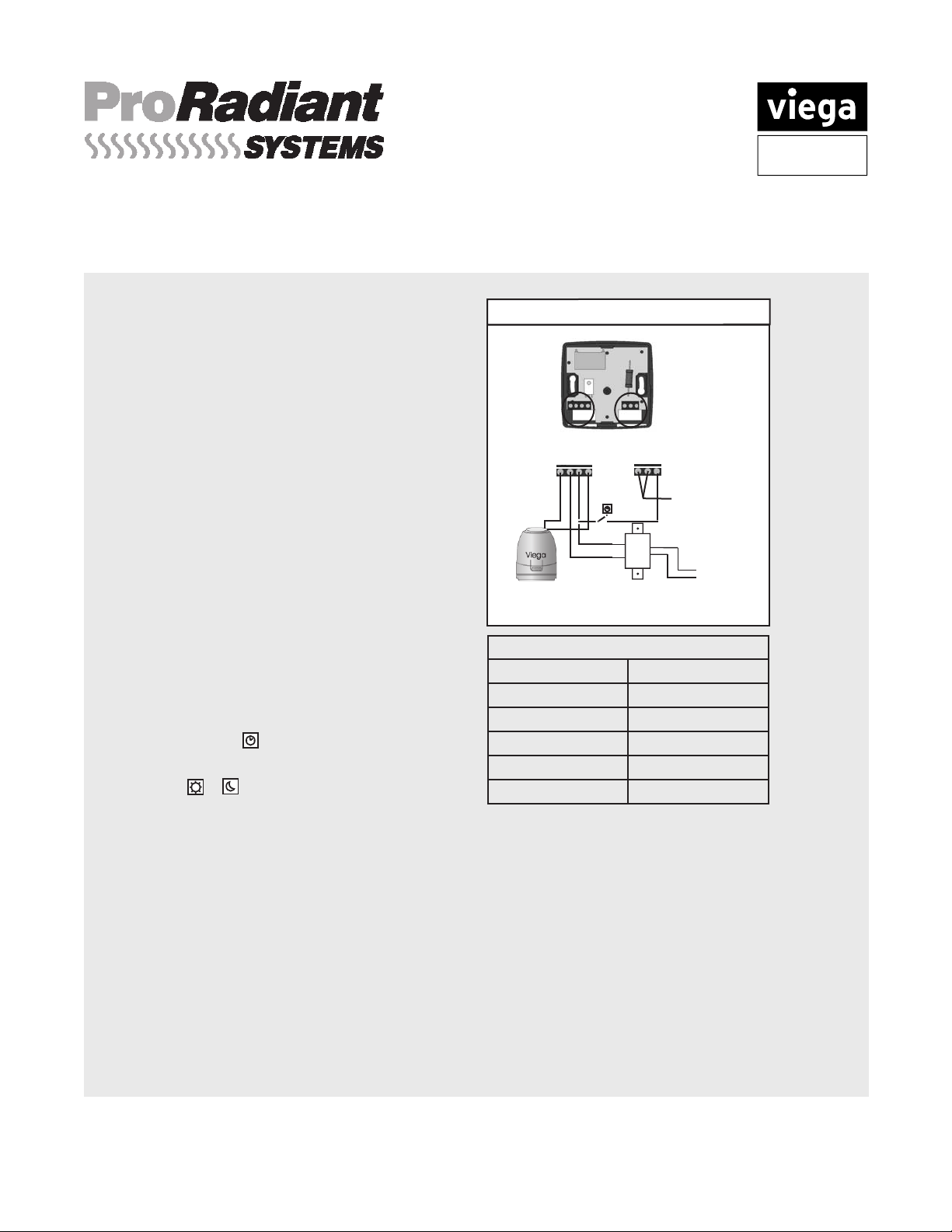
The Digital Thermostat Floor Sensor is a
two wire, water-sealed probe that can be used to
accurately measure slab or oor temperatures.
Floor Sensor should be placed in conduit for
protection and repair. 1/2" PEX (capped or
plugged) is commonly used as conduit for the slab
sensor. Sensor should be 18" from line voltage
(110V). If crossing line voltage wire cross at 90°
angle. Line voltage interference can result in
inaccurate readings of the sensor.
Connect one wire of the oor sensor to one 1.
"NTC" terminal of the Digital Thermostat.
Connect the other wire of the oor sensor 2.
to the other "NTC" terminal of the Digital
Thermostat.
(See diagram to right)
Wiring External Clock
The Digital Thermostat is compatible with an
external clock for timed set-back. Press the "OK"
button to select the External Clock Mode.
The thermostat display indicates weather it's in
Comfort Mode or Reduced Temperature Mode by
blinking the or symbols.
Advanced Wiring of Digital Thermostats
C C R W
NTC A/B
Optional
Floor sensor
Resistance Chart
Temperature
50°F
59°F
68°F
77°F
86°F
Resistance (kΩ)
~ 19.5kΩ
~ 15.5kΩ
~ 12.5kΩ
~ 10kΩ
~ 8kΩ
Powerhead(s) and Transformer
Connect "R" terminal of the thermostat to the 1.
transformer.
Splice into the "R" terminal wire and connect 2.
that to inlet side of an external clock.
Connect the outlet side of the external clock 3.
to A/B terminal on right side of thermostat.
Connect the "W" terminal of the thermostat to 4.
powerhead(s).
Connect a "C" terminal of the thermostat to 5.
the powerhead(s).
Connect a "C" terminal of the thermostat to 6.
Zone Control
1.
Connect "R" terminal of the thermostat to the
"R" of Zone Control.
Splice into the "R" terminal wire and connect 2.
that to inlet side of an external clock.
Connect the outlet side of the external clock to 3.
A/B terminal on right side of thermostat.
Connect the "W" terminal of the thermostat to 4.
"W" of the Zone Control.
Connect a "C" terminal of the thermostat to the 5.
"C" of the Zone Control.
(Not shown)
the transformer.
(See diagram top right)
301 N. Main, 9th Floor • Wichita, KS 67202 • Ph: 877-843-4262 • Fax: 800-976-9817 • E-Mail: [email protected] • www.viega.com
PI-PR-18050-0309 (Digital Thermostat)
Viega... The global leader in plumbing and heating systems.
4 of 4
 Loading...