

Page 1
Product
Instructions
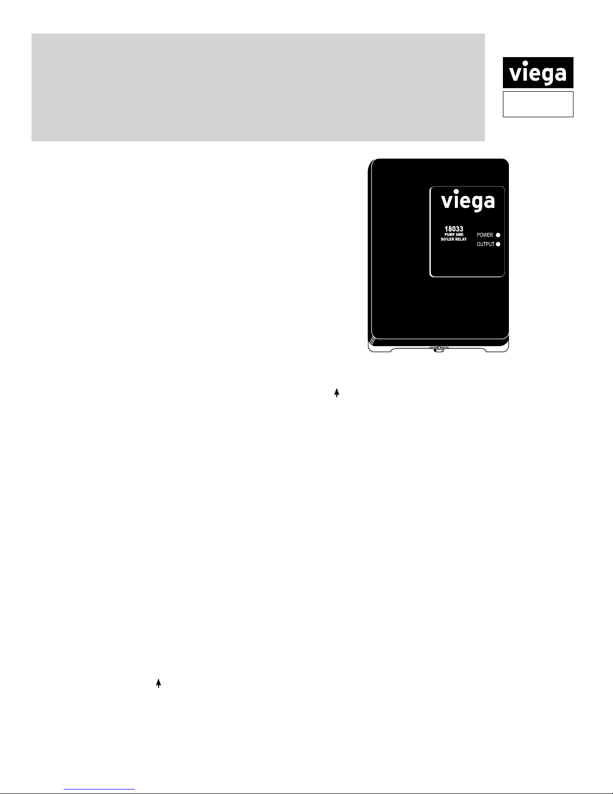
Pump and Boiler Relay
The Viega LLC Pump and Boiler Relay provides power to
circulators and can enable a boiler as well. Control may be
provided from a Viega Zone Control or Thermostat.
Features
• External Indicator Lights
• Universal Replaceability
• Snap-in PC Board
• Simple Wiring
• Sealed Relays
• Fuse Protected Outputs
• 100% Factory Tested
• Contractor Friendly PC Board Layout
• Universal Zone Control and Thermostat Compatibility
• UL Approved
Specifications
Transformer Voltage:120 VAC input
Input Voltage: 120/60/1 VAC
Maximum Combined Load: 12 Amps
Relay Connections: 1/3 hp ( 6FLA, 36 LRA )@ 120 vac
Thermostat Connection: 24 VAC Class 2 Output
Installation
Wiring connections must be made in accordance with all
applicable electrical codes. Use copper wire only. Failure to
follow this instruction can result in personal injury or death and/
or property damage. 12-18 gauge wire recommended for all 120
VAC connections with 9 in. lbs. max torque, 14-22 gauge wire for
thermostat connections with 9 in. lbs. max torque. 120VAC wiring
must have a minimum temperature rating of 75°C.
Jumper placement:
The jumper is factory installed between terminals H and 3 to
switch power on terminals 4 n/o and 4 n/c.
Operation
There are four common ways to connect the Pump and Boiler
Relay:
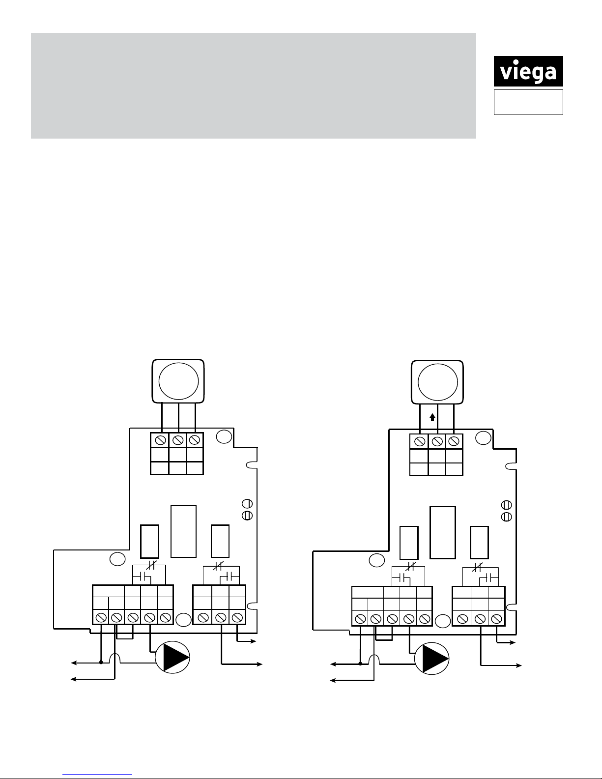
Wiring Diagram #1 Viega Digital Thermostat
(stock code 18050):
From the thermostat connect the R, W and C terminals to the
corresponding R, W and C terminals on the zone control. When
the thermostat calls for heat, the relay in the zone control is
energized and power is supplied to the circulator.
(R=R, W=W, C=C)
Wiring Diagram #2 Viega analog style thermostat
(stock code 18029, 18031):
From the thermostat connect the L terminal to the R terminal on
the zone control, connect the to the W terminal on the zone
control, and connect the N to the C terminal on the zone control.
When the thermostat calls for heat, the relay in the zone control
is energized and power is supplied to the circulator.
(L=R, =W, N=C)
Wiring Diagram #3 Zone Control:
Connect pump relay contacts of Zone Control to “T T” terminals
on the relay. When the Zone Control calls for heat, the relay is
energized and power is provided to the circulator (and/or dry
contact to the boiler).
Wiring Diagram #4 With 2-Wire Thermostat:
Connect a 2-wire thermostat to the “T T” terminals on the
relay. When the thermostat calls for heat, the relay is energized
and power is provided to the circulator (and/or dry contact to
the boiler).
Dimensions
Width 4-7/8"
Height 5-5/8"
Depth 2-3/8"
Troubleshooting
The external indicator lights show full functionality of the Pump
and Boiler Relay. The green light should always be on, indicating
that power is connected. If the green light is out check the
power connections at terminals N and H.
The red light shows a call for heat, indicating that power is
being supplied to the circulator (and/or a boiler enable signal is
provided).
If the Zone Control or thermostat is calling for heat but the red
light is out, check the thermostat wiring. If the red light is on but
the circulator is not running, check the circulator connection to
the relay.
301 N. Main, 9th Floor • Wichita, KS 67202 • Ph: 800-976-9819 • Fax: 316-425-7618 • www.viega.com
©2011, ProPress®, FostaPEX®, Seapress®, MegaPress®, MegaPressG
®
MANABLOC
GeoFusion
PI-PR-520949 0212 (Pump and Boiler Relay)
, Radiant Wizard®, S-no-Ice®, Snap Panel®, XL® and XL-C® are registered trademarks of Viega LLC. MiniBloc™, ProRadiant™, PolyAlloy™, SmartLoop™ and Zero Lead™ are trademarks of Viega LLC;
™
, ProPressG™ and ViegaPEX™ are trademarks of Viega GmbH & Co. KG.
Viega... The global leader in plumbing, heating and pipe joining systems
®
and Viega® are registered trademarks of Viega GmbH & Co. PureFlow®, Smart Connect®, Climate Panel®, Climate Mat®, Climate Trak®,
1 of 3
Page 2
Product
LED
INDICATORS
POWER
ONE ZONE
SWITCHING RELAY
C
24 v
COM
RW
TT
NH 3 44 6
ZONE 1
INPUT
120 VAC
N/O
N/O
N/CN/C
CIRCULATOR
TO: TT ON BOILER
65
COMCOM
JUMPER
FUSE
6 AMP
FUSE
6 AMP
Thermostats
18031
18029
L
N
3-WIRE
THERMOSTAT
LED
INDICATORS
POWER
ONE ZONE
SWITCHING RELAY
C
24 v
COM
RW
TT
NH 3 44 6
ZONE 1
INPUT
120 VAC
N/O N/ON/CN/C
TO: 120 VAC POWER
CIRCULATOR
TO: TT ON BOILER
65
COMCOM
JUMPER
FUSE
6 AMP
FUSE
6 AMP
3-WIRE
THERMOSTAT
Thermostats
18050
RCW
Instructions
Terminal Identication:
TT Zone Control or thermostat connection
24v COM Common side of 24V transformer, for 3-wire thermostats
N Neutral wire of power input (120 V)
H Hot wire of power input (120 V)
3 Common terminal for 4 n/o and 4 n/c
4 n/o Normally open terminal
4 n/c Normally closed terminal
6 n/o Normally open terminal
6 n/c Normally closed terminal
5 Common terminal for 6 n/o and 6 n/c
Viega Digital Thermostat (stock code 18050)
Connecting the Pump and Boiler Relay to a
Viega Thermostat
Viega 3 wire Thermostat (stock code 18031, 18029)
Connecting the Pump and Boiler Relay to a
Viega Thermostat
Wiring Diagram #1 Wiring Diagram #2
Viega... The global leader in plumbing, heating and pipe joining systems
©2011, ProPress®, FostaPEX®, Seapress®, MegaPress®, MegaPressG
®
MANABLOC
GeoFusion
PI-PR-520949 0212 (Pump and Boiler Relay)
, Radiant Wizard®, S-no-Ice®, Snap Panel®, XL® and XL-C® are registered trademarks of Viega LLC. MiniBloc™, ProRadiant™, PolyAlloy™, SmartLoop™ and Zero Lead™ are trademarks of Viega LLC;
™
, ProPressG™ and ViegaPEX™ are trademarks of Viega GmbH & Co. KG.
301 N. Main, 9th Floor • Wichita, KS 67202 • Ph: 800-976-9819 • Fax: 316-425-7618 • www.viega.com
®
and Viega® are registered trademarks of Viega GmbH & Co. PureFlow®, Smart Connect®, Climate Panel®, Climate Mat®, Climate Trak®,
2 of 3
Page 3

Product
ZONE
CONTROL
LED
INDICATORS
POWER
ONE ZONE
SWITCHING RELAY
C
24 v
COM
RW
TT
NH 3 44 6
ZONE 1
INPUT
120 VAC
N/O
N/O
N/CN/C
TO: 120 VAC POWER
CIRCULATOR
TO: TT ON BOILER
65
COMCOM
JUMPER
FUSE
6 AMP
FUSE
6 AMP
DRY BOILER
CONTACTS
LED
INDICATORS
POWER
ONE ZONE
SWITCHING RELAY
C
24 v
COM
RW
TT
NH 3 44 6
ZONE 1
INPUT
120 VAC
N/O N/ON/CN/C
TO: 120 VAC POWER
CIRCULATOR
TO: TT ON BOILER
65
COMCOM
JUMPER
FUSE
6 AMP
FUSE
6 AMP
2-WIRE
THERMOSTAT
Instructions
Zone Control
Connecting the Pump and Boiler Relay to a Viega
Zone Control
2 Wire Thermostat
Connecting the Pump and Boiler Relay to a
2-wire thermostat
Wiring Diagram #3 Wiring Diagram #4
©2011, ProPress®, FostaPEX®, Seapress®, MegaPress®, MegaPressG
MANABLOC
GeoFusion
301 N. Main, 9th Floor • Wichita, KS 67202 • Ph: 800-976-9819 • Fax: 316-425-7618 • www.viega.com
®
, Radiant Wizard®, S-no-Ice®, Snap Panel®, XL® and XL-C® are registered trademarks of Viega LLC. MiniBloc™, ProRadiant™, PolyAlloy™, SmartLoop™ and Zero Lead™ are trademarks of Viega LLC;
™
, ProPressG™ and ViegaPEX™ are trademarks of Viega GmbH & Co. KG.
Viega... The global leader in plumbing, heating and pipe joining systems
PI-PR-520949 0212 (Pump and Boiler Relay)
®
and Viega® are registered trademarks of Viega GmbH & Co. PureFlow®, Smart Connect®, Climate Panel®, Climate Mat®, Climate Trak®,
3 of 3
 Loading...