

Page 1
Product
Instructions
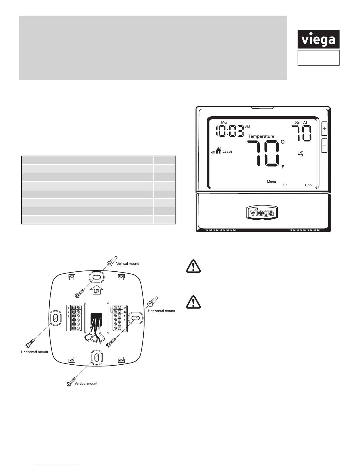
Viega® Multifunctional Heat/Cool Thermostat
The Viega multifunctional heat/cool thermostat is easy
to install, easy to wire and easy to program. It can be
used for three stages of heating and two stages of
cooling, making it ideal for many applications. Installation
instructions can be found below.
Thermostat applications guide
Description
Gas or Oil Heat Yes
Electric Furnace Yes
Heat Pump (No Aux. or Emergency Heat) Yes
Heat Pump (with Aux. or Emergency Heat) Yes
Multi-stage Systems Yes
Heat Only Systems Yes
Cool Only Systems Ye s
Mounting the subbase
W/E
W2
For vertical mount put one screw top and one screw bottom.
For horizontal mount put one screw left and one screw right.
The thermostat can be mounted directly to the wall or it can
be mounted to a wall box. Use the vertical mounting screw
location to attach to a wall box.
Y2
Part Number 15118
Caution: Electrical Hazard
Failure to disconnect the power before beginning
to install this product can cause electrical shock or
equipment damage.
Mercury Notice:
All of our products are mercury free. However, if the
product you are replacing contains mercury, dispose of it
properly. Your local waste management authority can give
you instructions on recycling and proper disposal.
A trained, experienced technician must install this
product.
damage this product or cause a hazardous condition if
you fail to follow these instructions.
Carefully read these instructions. You could
Viega LLC, 301 N. Main, 9th Floor • Wichita, KS 67202 • Ph: 800-976-9819 • Fax: 316-425-7618
PI-PR 566441 0114 (Multifunctional Thermostat)
1 of 16
Page 2
Product
Instructions
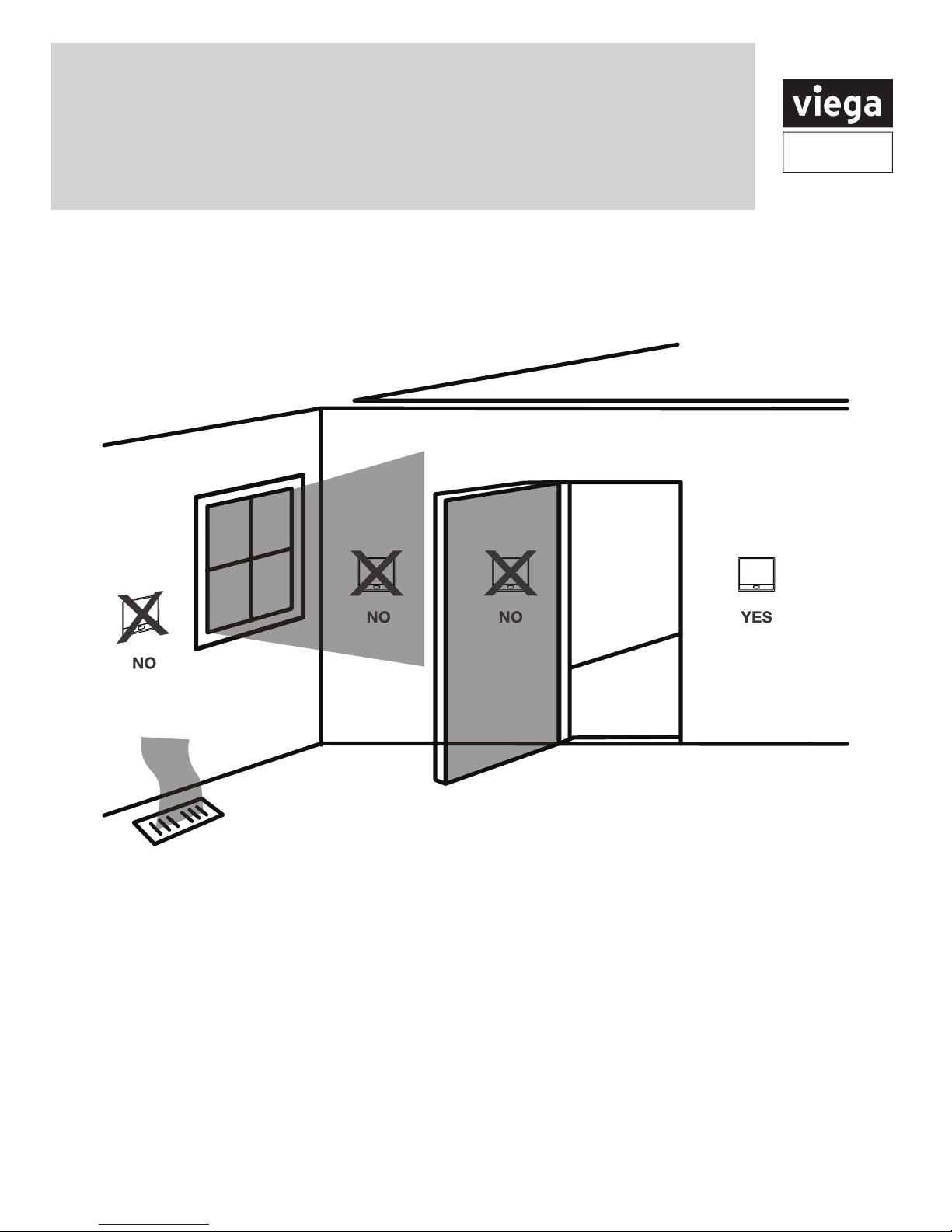
Installation tips
Wall locations
The thermostat should be installed approximately 4 to 5 feet above the
oor. Select an area with average temperature and good air circulation.
Do not install thermostat in locations:
• Close to hot or cold air ducts
• That are in direct sunlight
• With an outside wall behind the thermostat
• In areas that do not require conditioning
• Where there are dead spots or drafts (in corners or
behind doors
• Where there might be concealed chimneys or pipes
Viega LLC, 301 N. Main, 9th Floor • Wichita, KS 67202 • Ph: 800-976-9819 • Fax: 316-425-7618
PI-PR 566441 0114 (Multifunctional Thermostat)
NOTE: Pick an installation location that is easy for the
user to access. The temperature of the location should be
representative of the building
2 of 16
Page 3
Product
Instructions
Thermostat wiring
1. If you are replacing a thermostat, make note of the
terminal connections on the thermostat that is being
replaced. In some cases the wiring connections will
not be color coded. For example, the green wire
may not be connected to the G terminal.
2. Loosen the terminal block screws. Insert wires then
retighten terminal block screws.
Viega thermostat terminal conversion
Thermostat
15118
RH
C
W/E
Thermostats
15116
15117
RH
C
W
Zone Control
18060
18062
18050
R
C
W
Zone Control
18032
Thermostat
18029
L
N
Power type
• 3 wire
• 3 wire with battery backup
• 2 wire with battery
Wire specifications
Use shielded or non-shielded 18-22 gauge thermostat wire.
Wiring Tips
C terminal
The C (common wire) terminal does not have to be
connected when the thermostat is powered by batteries.
NOTE: In systems with no emergency heat relay a jumper
can be installed between E and W2 to turn thermostat into
a single stage control.
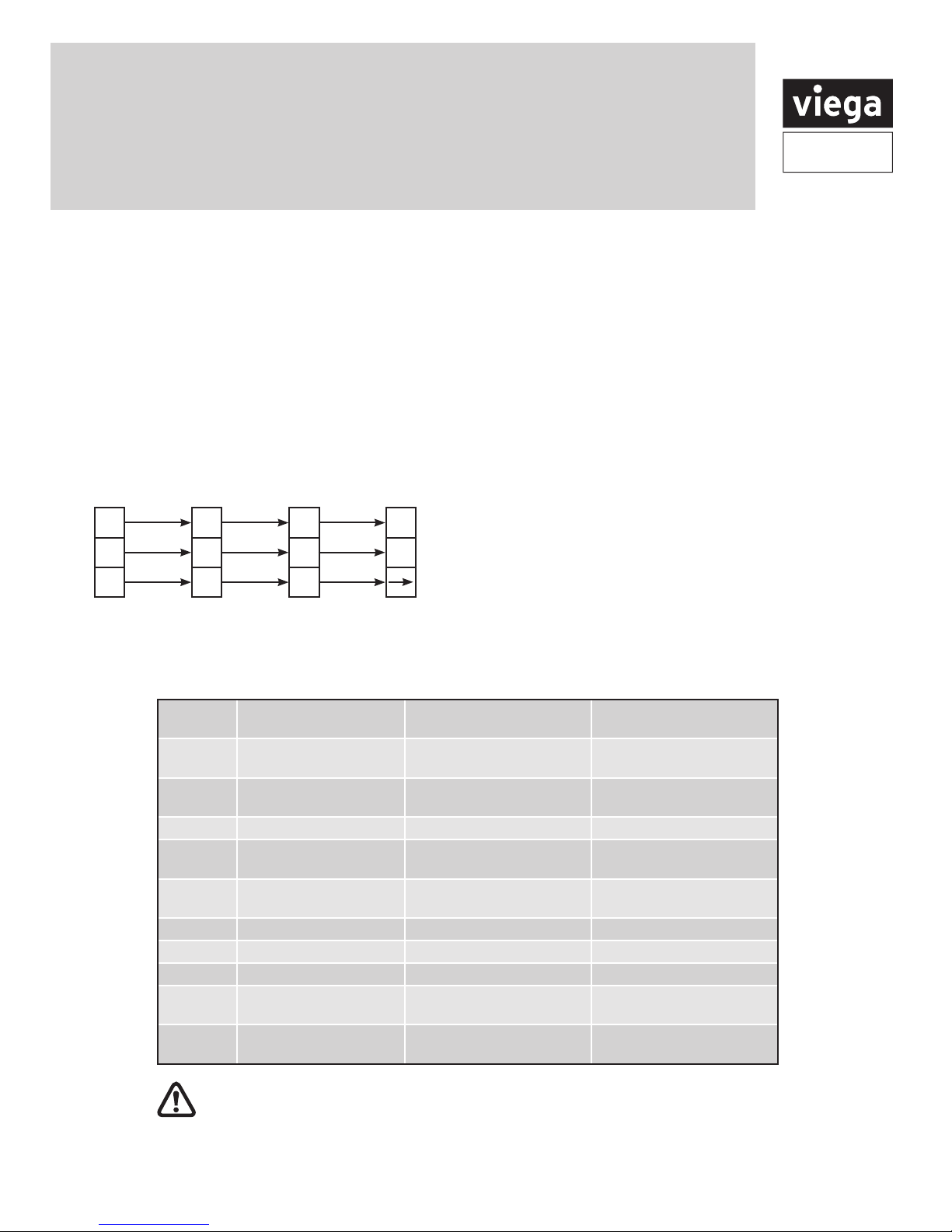
Terminal designations
This thermostat is shipped from the factory to operate a conventional heating and cooling system. See the "heat pump"
conguration step on page 11 of this manual to congure the thermostat for heat pump applications.
2 Heat 2 Cool
Terminal
RC Transformer power
RH Transformer power
C Transformer common Transformer common Transformer common
B Energized in heating Heat pump changeover
O Energized in heating Heat pump changeover
G Fan relay Fan relay Fan relay
W/E First stage of heat Emergency heat relay Emergency heat relay
Y First stage of cool First stage of heat & cool First stage of heat & cool
Y2 Second stage of cool Second stage of cool Second stage of cool &
W2 Second stage of heat Auxiliary heat relay,
Warning:
must conform to Class II circuits per the NEC Code.
Viega LLC, 301 N. Main, 9th Floor • Wichita, KS 67202 • Ph: 800-976-9819 • Fax: 316-425-7618
PI-PR 566441 0114 (Multifunctional Thermostat)
Conventional System
(cooling)
(heating)
All components of the control system and the thermostat installation
2 Heat 2 Cool
Heat Pump System
Transformer power
(cooling)
Transformer power
(heating)
valve energized in cooling
valve energized in cooling
second stage of heat
3 Heat 2 Cool
Heat Pump System
Transformer power
(cooling)
Transformer power
(heating)
Heat pump changeover
valve energized in heating
Heat pump changeover
valve energized in heating
second stage of heat
Auxilary heat relay,
third stage of heat
3 of 16
Page 4
Product
Instructions
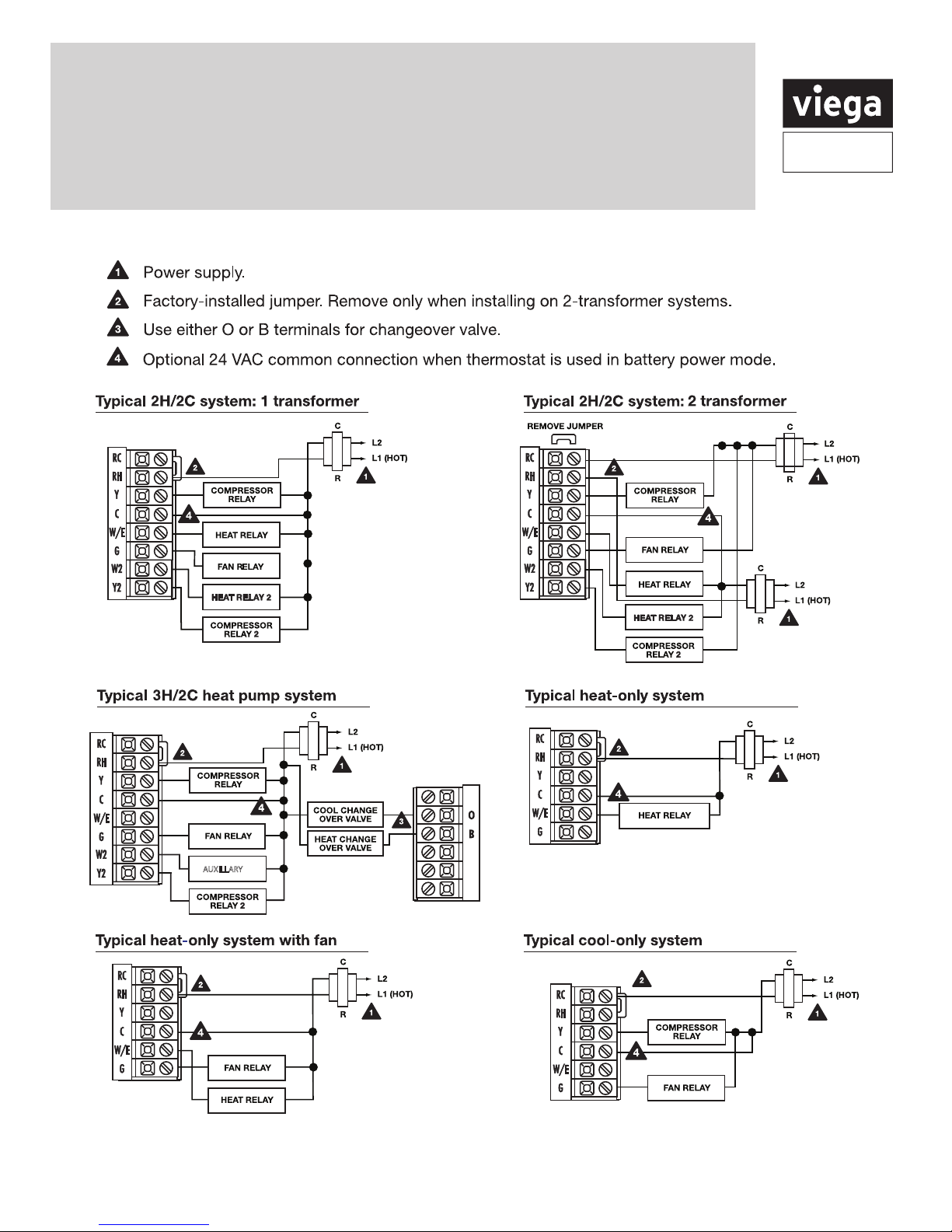
Typical industry wiring diagrams
AUXILLARY
NOTE: In many systems with no emergency heat relay a jumper can be installed between E and W2
Viega LLC, 301 N. Main, 9th Floor • Wichita, KS 67202 • Ph: 800-976-9819 • Fax: 316-425-7618
PI-PR 566441 0114 (Multifunctional Thermostat)
4 of 16
Page 5
Product
Instructions
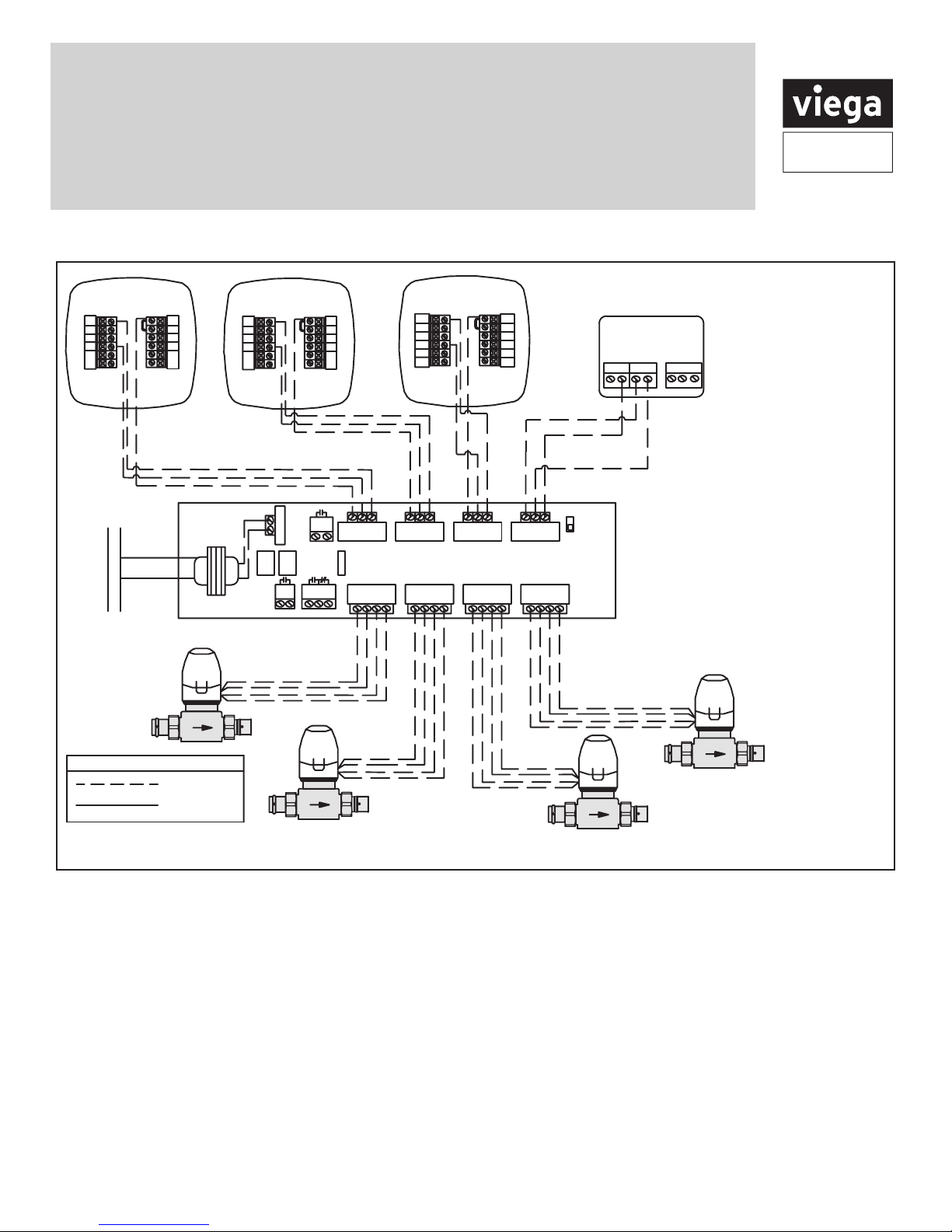
Viega wiring diagrams
Thermostat -15116
C
O
B
W
120 V AC
Power Supply
L
N
LEGEND: Zone Controls
RH
RC
G
Y
R
C
Viega
Low Voltage
Line Voltage
Thermostat -15117
C
O
B
W
ISOLATED
END
SWITCH
POWER IN
FUSE
(5 AMP MAX)
PUMP
N/O N/CCOM
END
ZONE 4 RELAY
SWITCH
Viega
RH
RC
G
Y
R W CR
ZONE 1
Yellow
Yellow
Red
Red
Thermostat -15118
C
O
B
W/E
W2
W C
ZONE 1
1234
ZONE 2
ZONE CONTROL (18060, 18062)
WITH OPTIONAL PRIORITY
ZONE 2 ZONE 3
1 2 34 1234
Yellow
Yellow
Red
Red
ZONE 3 ZONE 4
RH
RC
G
Y
Y2
W CR WCR
Red
Red
Yellow
Yellow
ZONE 4
ZONE 4 PRIORITY
OFF
ON
Red
Red
Yellow
Yellow
Viega
Thermostat -18050
CC RW NTC A/B
Part Numbers:
15116, 15117 and 15118
1. Connect the "RH" terminal
from the thermostat to "R"
terminal on the zone control
2. Connect the "W" terminal
from the thermostat to "W"
terminal on the zone control,
for part number 15118
connect "W/E" terminal from
the thermostat to "W" terminal
on the zone control
3. Connect the "C" terminal from
the thermostat to the "C"
terminal on the zone control
Viega
Connecting Viega thermostats and zone valves to the Viega zone control
Viega LLC, 301 N. Main, 9th Floor • Wichita, KS 67202 • Ph: 800-976-9819 • Fax: 316-425-7618
PI-PR 566441 0114 (Multifunctional Thermostat)
5 of 16
Page 6

Product
Line Voltage
Low Voltage
LEGEND: Zone Controls
Sensors
Line Voltage
Low Voltage
LEGEND: Zone Controls
Sensors
Line Voltage
Low Voltage
LEGEND: Zone Controls
Sensors
LEGEND: Zone Controls
LEGEND: Zone Controls
Instructions
Thermostat -15116
C
O
B
W
120 V AC
Power Supply
L
N
RH
RC
G
Y
R
C
Thermostat -15117
C
O
B
W
POWER IN
PUMP
END
SWITCH
Viega
POWERHEAD (15061)
2 WIRE, 24 V,
FOR USE WITH
STAINLESS MANIFOLD
Connecting Viega thermostats to
the Viega zone control
Thermostat -15118
RH
RC
G
Y
ISOLATED
END
W CR W CR W CR W CR
SWITCH
ZONE 1 ZONE 2 ZONE 3 ZONE 4
FUSE
(5 AMP MAX)
N/O N/CCOM
ZONE 4 RELAY
ZONE 1 ZONE 2 ZONE 3 ZONE 4
1 2 3 4
C
O
B
W/E
W2
ZONE CONTROL (18060, 18062)
WITH OPTIONAL PRIORITY
1 2 3 4 1 2 3 4
JUMPER
3&4
Viega
Yellow
Yellow
Red
Red
RH
RC
Y2
Yellow
Yellow
G
Y
Thermostat -18050
C C R W NTC A/B
Low Voltage
Line Voltage
Part Numbers:
15116, 15117 and 15118
1. Connect the "RH" terminal
from the thermostat to "R"
ZONE 4 PRIORITY
OFF
ON
terminal on the zone control
2. Connect the "W" terminal
from the thermostat to "W"
terminal on the zone control,
for part number 15118
connect "W/E" terminal from
JUMPER
3&4
IF PRIORITY
IS USED
the thermostat to "W" terminal
on the zone control
3. Connect the "C" terminal from
the thermostat to the "C"
terminal on the zone control
Viega
Red
Red
Yellow
Yellow
Viega
POWERHEAD (15064)
Red
Red
4 WIRE, 24 V,
FOR USE WITH
STAINLESS MANIFOLD
Low Voltage
Line Voltage
Thermostat -15116
C
O
B
W
Class II
Transformer
C
R
4
powerheads
may be
connected
to each
thermostat
Connecting
Viega
thermostats
to 2 wire
powerheads
PI-PR 566441 0114 (Multifunctional Thermostat)
ViegaViega
120 V AC
Power Supply
N
L
Viega LLC, 301 N. Main, 9th Floor • Wichita, KS 67202 • Ph: 800-976-9819 • Fax: 316-425-7618
4 powerheads may
be connected to
each thermostat
RH
RC
G
Y
TO T-T BOILER CONTACT, PUMP
RELAY OR OTHER AUXILIARY
DEVICE REQUIRING CONTACT
CLOSURE. SEE NOTE 2.
LEGEND: Zone Controls
Low Voltage
Line Voltage
Viega
Red
Red
Yellow
Yellow
120 V AC
Power Supply
N
Connecting Viega thermostats
to 4 wire powerheads
L
Thermostat -15116
C
O
B
W
Class II
Transformer
C
RH
RC
G
Y
R
6 of 16
Page 7

Product
Instructions
Attaching the thermostat to the subbase
Align the 4 tabs on the subbase with corresponding slots
on the back of the thermostat, then push gently until the
thermostat snaps in place.
Battery installation
Battery installation is recommended even if thermostat
is hardwired (C terminal connected). When thermostat
is hardwired and batteries are installed, the thermostat
will activate a compressor delay of 5 minutes when the
thermostat detects a power outage from the hardwired
power supply (batteries included).
On the back of the thermostat
insert 2 AA alkaline batteries
(included).
Important:
The low battery indicator is displayed when the AA battery power is low. If the user fails to replace the battery
within 21 days, the thermostat display will only show the low battery indicator as a nal warning before the thermostat
becomes inoperable. For more information, see Battery installation and replacement above.
Viega LLC, 301 N. Main, 9th Floor • Wichita, KS 67202 • Ph: 800-976-9819 • Fax: 316-425-7618
PI-PR 566441 0114 (Multifunctional Thermostat)
7 of 16
Page 8

Product
Instructions
Thermostat display
1
LCD
2
Glow in the dark light button
• Push the glow in the dark button and the screen will
illuminate.
3
Fan button
• Set to AUTO to run the fan anytime heating or
cooling is running.
• Set to ON to run the fan at all times.
4
System button
• Set to heating/cooling or off.
5
Menu buttons access door
6
Temperature setpoint buttons
• Use the
temperature.
7
Menu button
8
10
-
User program buttons
PI-PR 566441 0114 (Multifunctional Thermostat)
or
+
Viega LLC, 301 N. Main, 9th Floor • Wichita, KS 67202 • Ph: 800-976-9819 • Fax: 316-425-7618
buttons to adjust the room
–
Important:
The low battery indicator is displayed when the AA
battery power is low. If the user fails to replace the
battery within 21 days, the screen will only show the low
battery indicator but maintain all functionality. If the user
fails to replace the batteries after an additional 21 days
(days 22-42 since rst “low battery” display) the set points
will change to 55°F (Heating) and 85°F (Cooling). If the
user adjusts these setpoints away from these it will hold
for 4 hours then return to either 55°F or 85°F. After day
42 the batteries must be replaced immediately to avoid
freezing or overheating because the thermostat will shut
the unit off until the battery is changed.
8 of 16
Page 9

Product
Instructions
Programming the thermostat
This thermostat has a technician setup menu for easy
installer conguration. To setup the thermostat for your
particular application:
1. Press MENU button.
2. Press and hold TECH SET button for 3 seconds. This
3 second delay is designed so that homeowners do
not accidentally access the installer settings.
Technician Setup Steps
Filter Change
Reminder
This feature will
ash "FILT" in the
display after the
elapsed run time to
remind the user to
change the lter. A
setting of "off" will
disable this feature
LCD will Show
Room
Temperature
Calibration
This feature
allows the installer
to change the
calibration of the
room temperature
display. For
example, if the
thermostat reads
70° and you would
like it to read 72°
then select +2.
Minimum
Compressor On
Time
This feature
allows the
installer to select
the minimum
run time for the
compressor. For
example: A setting
of 4 will force the
compressor to
run for at least 4
minutes every time
the compressor
turns on,
regardless of the
room temperature
Compressor
Short Cycle Delay Cooling Swing Heating Swing Keypad Lockout
The compressor
short cycle delay
protects the
compressor from
"short cycling".
This feature will
not allow the
compressor to
be turned on for
5 minutes after it
was last turned off.
3. Congure the installer options as desired using the
table below.
Use the
or
+
keys to change settings and the
–
NEXT STEP or PREV STEP key to move from one
option to another. Note: Only press DONE key when
you want to exit the Technician Setup options.
NOTE: Only press DONE key when you want to exit
the Technician Setup options.
4. Press DONE key to exit.
The swing setting,
often called "cycle
rate", "differential"
or "anticipation"
is adjustable. A
smaller swing
setting will cause
more frequent
cycles and a larger
swing setting
will cause fewer
cycles.
The swing setting,
often called "cycle
rate", "differential"
or "anticipation"
is adjustable. A
smaller swing
setting will cause
more frequent
cycles and a larger
swing setting
will cause fewer
cycles.
Keypad lockout
allows you to
congure the
thermostat so that
none or some of
the keys do not
function.
Adjustment Options
You can adjust
the lter change
reminder from "off"
to 2000 hours of
runtime in 50 hour
increments.
Factory Default Settings
Off 0°F Off On 0.5°F 0.4°F PA
You can adjust the
room temperature
display to read
-4°F to +4°F above
or below the
factory calibrated
reading.
You can select
the minimum
compressor run
time from "off",
"3", "4", or "5"
minutes. If 3, 4,
or 5 is selected,
the compressor
will run for at least
the selected time
before turning off.
NOTE: To lock the keypad hold down the
the key pad hold down the
Viega LLC, 301 N. Main, 9th Floor • Wichita, KS 67202 • Ph: 800-976-9819 • Fax: 316-425-7618
PI-PR 566441 0114 (Multifunctional Thermostat)
+
and
Selecting "on"
will not allow the
compressor to
be turned on for
5 minutes after
the last time the
compressor was
on. Select "off" to
remove this delay.
and
+
keys for 3 seconds.
–
–
The cooling
swing setting is
adjustable from
±0.2°F to ±2°F. For
example: A swing
setting of 0.5°F will
turn the cooling on
at approximately
0.5°F above the
setpoint and turn
the cooling off
at approximately
0.5°F Below the
setpoint.
The heating
swing setting is
adjustable from
±0.2°F to ±2°F. For
example: A swing
setting of 0.5°F will
turn the heating on
at approximately
0.5°F below the
setpoint and turn
the heating off
at approximately
0.5°F above the
setpoint.
Pick PA or FU
PA = partial
keypad lockout,
which locks all the
keys except the
or – keys.
FU = Full keypad
lockout, which
locks out all the
keys.
Note: Keypad
lockout
instructions are
below.
+
keys for 3 seconds. You will see a lock in the display. To unlock
9 of 16
Page 10

Product
Instructions
Technician Setup Steps (continued from the previous page)
Heating
Temperature
Setpoint Limit
This feature
allows you to set
maximum heat
setpoint value.
The setpoint
temperature
cannot be raised
above this value.
LCD will Show
Cooling
Temperature
Setpoint Limit °F or °C
This feature
allow you to set
a minimum cool
setpoint value.
The setpoint
temperature
cannot be lowered
below this value.
This feature allows
you to display
temperatures in
either Fahrenheit
or Celsius
12 or 24
Hour Clock Fan Operation
You can select
either a 12 or 24
hour clock setting.
Select GAS for
systems that
control the fan
during a call for
heat.
Select ELEC
to have the
thermostat control
the fan during a
call for heat.
Morning
Recovery Program Options
This feature turns
your system on
before the WAKE
programming
time to ensure the
environment is at
the WAKE setpoint
when the WAKE
time period begins.
The recovery
period will change
based on previous
days knowledge.
For 2 time periods,
the system will
turn on before
the occupied
programmable
time.
You can congure
this thermostat
to have a 7 day
program, a 5+1+1
program or
nonprogrammable.
Adjustment Options
Use the + or –
key to select the
maximum heat
setpoint.
Range 44°F - 90°F
Factory Default Settings
90°F 44°F °F 12 Hour Clock GAS ON 5d
Use the
key to select the
minumum cool
setpoint.
Range 44°F - 90°F
+
or –
Select °F for
Fahrenheit or °C
for Celsius
Use the
key to select 12 or
24 hour clock.
+
or –
GAS or ELEC Use the
key to turn on or
off.
+
or –
Use the
key to select 7d
for 7 day, 5d for
5+1+1 or 0d for
nonprogrammable.
+
or –
Viega LLC, 301 N. Main, 9th Floor • Wichita, KS 67202 • Ph: 800-976-9819 • Fax: 316-425-7618
PI-PR 566441 0114 (Multifunctional Thermostat)
10 of 16
Page 11

Product
Instructions
Technician Setup Steps (continued from the previous page)
Time Periods Display Light
You can congure
this thermostat
to have 2 or 4
programmable
time periods per
day.
2 time periods
is Occupied/
Unoccupied.
4 time periods
is Wake, Leave,
Return, Sleep.
LCD will Show
The display light
can be congured
to stay on at all
times or come on
when any key is
pressed.
NOTE: HARDWIRE
ONLY Keeping
the display light
continually "ON"
will greatly reduce
battery life.
Contractor Call
Number Beep Heat Pump
Allows you to
put your phone
number in the
display.
You can choose
ON or OFF
When any key is
pressed an audible
beep will sound.
You can choose
ON or OFF
When turned on
the thermostat
will operate a heat
pump.
1. EM. Heat will
show as an option
in the system
switch.
2. Y will be rst
stage of heat &
cool, W/E will be
emergency heat
relay & W2 will be
auxiliary heat relay.
Operating Modes
Selection
You can congure
the system switch
for the particular
application:
Heat - Off - Cool,
Heat - Off,
Cool - Off,
Heat-Off-Cool-Auto
NOTE: EM, Heat
will show if in heat
pump mode.
Gas Auxiliary for
Heat Pump
This option will
turn the heat pump
off 45 seconds
after the auxiliary
heat relay turns on.
For 2 stage heat
applications, the
rst stage will turn
off 45 seconds
after the auxiliary
stage turns on.
For 3 stage heat
applications, the
rst and second
stage will turn off
45 seconds after
the auxiliary stage
turns on.
Adjustment Options
Use the + or –
key to select 2 or
4 time periods per
day.
Factory Default Settings
4 OFF OFF ON OFF Heat-Off-Cool OFF
OFF congures
display light to
come on when
the light key or
any other key is
pressed.
ON congures the
display light to stay
on. Use the
–
key to turn on
or off.
+
If selected on,
you will see the
input screen after
pressing next step.
Use the
key to select the
desired number
and the FAN or
SYSTEM key
or
to move from
one character to
another. See note
below operation.
+
or –
Swing Setting Tip
The second stage will turn on at 2x the swing setting. The
second stage will turn off when 1x the swing is reached.
For example, if the swing setting is .8 degrees for heating
and the thermostat is set at 70°F, the rst stage will turn
on at approximately 69.2°F and the rst will turn off at
On is selected the
beep will sound.
OFF is selected,
there is no sound.
NOTE: If contractor Call Number is selected ON, your
phone number will show in the display if there has been
a continuous call for heating or cooling for 24 hours or if
the light button is held down for 3 seconds. To remove the
phone number from the display, hold the light button for 3
seconds.
OFF congures
the thermostat for
non heat pump
systems.
ON congures the
thermostat for heat
pump systems.
Use the
desired application
is ashing.
+
–
key until the
or
70.8°F. If third stage is used, it will turn on at 3x the swing
and turn off at approximately 2x the swing.
For heat pump
systems that are
"dual fuel" (use
a gas furnace for
auxiliary stage
heat) you can turn
this feature on to
turn off the heat
pump when the
auxiliary stage of
heating has been
called for.
Viega LLC, 301 N. Main, 9th Floor • Wichita, KS 67202 • Ph: 800-976-9819 • Fax: 316-425-7618
PI-PR 566441 0114 (Multifunctional Thermostat)
11 of 16
Page 12

Product
Instructions
Technician Setup Steps (continued from the previous page)
Stages of Heat
You can congure
the thermostat to
operate a 3 stage
heat pump system.
2H 2C =
2 heat, 2 cool
3H 2C =
3 heat, 2 cool
LCD will Show
Adjustment Options
+
Use the
–
key to change
between 2 heat
and 3 heat
2 heat will use Y1
as rst stage and
W2 as auxiliary.
3 heat will use
Y1 as rst stage,
Y2 as second
stage and W2 as
auxiliary.
Factory Default Settings
2 Stages OFF OFF OFF
or
Cooling Fan
Delay Satisfy Setpoint Staging Delay
The cooling fan
delay setting will
delay the fan from
coming on in cool
mode and keep
running after the
compressor shuts
off for a short time
to save energy in
some systems.
You can select
the Cooling Fan
Delay from "Off"
"15" "30" "60" or
"90" seconds. If
15, 30, 60 or 90 is
selected the fan
will not turn on for
that many seconds
when there is a call
for cool and will
run for that many
seconds after
satisfying a call for
cool.
This feature allows
the thermostat
to keep multiple
stages of heat or
cool energized
until setpoint is
satised.
Use the
key to turn on or
off.
+
or –
This feature allows
a delay to occur
when a second
and third stage
is needed. This
allows the previous
stage extra time to
satisfy setpoint.
Use the
key to select OFF,
5, 10, 15, 30, 45,
62, 90.
+
or –
Viega LLC, 301 N. Main, 9th Floor • Wichita, KS 67202 • Ph: 800-976-9819 • Fax: 316-425-7618
PI-PR 566441 0114 (Multifunctional Thermostat)
12 of 16
Page 13

Product
Instructions
Programming the thermostat
Set time
Follow the steps below to set the day of the week and
current time:
1. Press MENU.
2. Press SET TIME.
or
+
or
or
–
key
–
3. Day of the week will be flashing. Use the
key to select the current day of the week.
–
4. Press NEXT STEP.
5. The current hour is flashing. Use the
key to select the current hour. When using 12-hour
time, make sure the correct a.m. or p.m. choice is
selected.
6. Press NEXT STEP.
7. Minutes are now flashing. Use the
to select current minutes.
8. Press DONE when completed.
+
+
Programming
All our programmable thermostats are shipped with an
energy saving pre-program. You can customize this
default program by following the Set Program Schedule.
Your thermostat can be programmed to have each day of
the week programmed uniquely (7 days), all the weekdays
the same, a separate program for Saturday, and a separate
program for Sunday (5+1+1), or non-programmable.
There can be four time periods for each program (WAKE,
LEAVE, RETURN, SLEEP), or two time periods for each
program (OCCUPIED, UNOCCUPIED). This thermostat
has a programmable fan feature, which allow you to run
the fan continuously during any time period.
Factory Default Program for 4 Time Periods
Setpoint
Day of
the Week Events Time
Weekday
Saturday
Sunday
Day of
the Week Events Time
Weekday Occupied 8 a.m. 70°F (21°C) 73°F (23°C)
Saturday Occupied 8 a.m. 70°F (21°C) 73°F (23°C
Sunday Occupied 8 a.m. 70°F (21°C) 73°F (23°C)
Wake
Leave
Return
Sleep
Wake
Leave
Return
Sleep
Wake
Leave
Return
Sleep
Factory Default Program for 2 Time Periods
Unoccupied 6 p.m. 64°F (18°C) 80°F (27°C)
Unoccupied 6 p.m. 64°F (18°C) 80°F (27°C)
Unoccupied 6 p.m. 64°F (18°C) 80°F (27°C)
6 a.m. 70°F (21°C) 75°F (24°C)
8 a.m. 62°F (17°C) 83°F (28°C)
6 p.m. 70°F (21°C) 75°F (24°C)
10 p.m. 62°F (17°C) 78°F (26°C)
8 a.m. 70°F (21°C) 75°F (24°C)
10 a.m. 62°F (17°C) 83°F (28°C)
6 p.m. 70°F (21°C) 75°F (24°C)
11 p.m. 62°F (17°C) 78°F (26°C)
8 a.m. 70°F (21°C) 75°F (24°C)
10 a.m. 62°F (17°C) 83°F (28°C)
6 p.m. 70°F (21°C) 75°F (24°C)
11 p.m. 62°F (17°C) 78°F (26°C)
Temperature
(Heat)
Setpoint
Temperature
(Heat)
Setpoint
Temperature
(Cool)
Setpoint
Temperature
(Cool)
Viega LLC, 301 N. Main, 9th Floor • Wichita, KS 67202 • Ph: 800-976-9819 • Fax: 316-425-7618
PI-PR 566441 0114 (Multifunctional Thermostat)
13 of 16
Page 14

Product
Instructions
You can use the table below to plan your customized
program schedule.
Factory Default Program for 4 Time Periods
Setpoint
Temperature
(Cool)
Day of
the Week Events Time
Weekday
Saturday
Sunday
Wake
Leave
Return
Sleep
Wake
Leave
Return
Sleep
Wake
Leave
Return
Sleep
Setpoint
Temperature
(Heat)
Set program schedule for four time periods
(WAKE, LEAVE, RETURN, SLEEP)
To customize your 5+1+1 program schedule, follow these
steps:
Weekday:
1. Select HEAT or COOL using the SYSTEM key.
NOTE: You have to program heat and cool each
separately.
2. Press MENU.
3. Press SET SCHED. NOTE: Monday-Friday is
displayed and the WAKE icon is shown. You are
now programming the wake time period for the
weekday setting.
4. Time is flashing. Use the
make your time selection for the weekday WAKE
time period. NOTE: If you want the fan to run
continuously during this time period, select ON with
the FAN key.
or
+
–
key to
5. Press NEXT STEP.
6. The setpoint temperature is flashing. Use the
or
weekday WAKE period.
7. Press NEXT STEP.
8. Repeat steps 4 through 7 for weekday LEAVE time
period, for weekday RETURN time period, and for
weekday SLEEP time period.
Saturday:
9. Repeat steps 4 through 7 for Saturday WAKE
time period, for Saturday LEAVE time period, for
Saturday RETURN time period, and for Saturday
SLEEP time period.
Sunday:
10. Repeat steps 4 through 7 for Sunday WAKE time period,
for Sunday LEAVE time period, for Sunday RETURN
time period, and for Sunday SLEEP time period.
To customize your 7 day program schedule, follow these steps:
Monday:
1. Select HEAT or COOL using the SYSTEM key. You
have to program heat and cool each separately.
2. Press MENU.
3. Press SET SCHED. NOTE: Monday is displayed
and the WAKE icon is shown. You are now
programming the WAKE time period for the Monday
setting.
4. Time is flashing. Use the
make your time selection for the Monday WAKE
time period. NOTE: If you want the fan to run
continuously during this time period, select ON with
the FAN key.
5. Press NEXT STEP.
6. The setpoint temperature is flashing. Use the
or
Monday WAKE period.
7. Press NEXT STEP.
8. Repeat steps 4 thru 7 for Monday LEAVE time
period, for Monday RETURN time period, and for
Monday SLEEP time period.
Tuesday, Wednesday, Thursday, Friday, Saturday, Sunday:
Repeat steps 4 thru 8 for the remaining days of the week.
key to make your setpoint selection for the
–
or
+
key to make your setpoint selection for the
–
–
key to
+
+
Viega LLC, 301 N. Main, 9th Floor • Wichita, KS 67202 • Ph: 800-976-9819 • Fax: 316-425-7618
PI-PR 566441 0114 (Multifunctional Thermostat)
14 of 16
Page 15

Product
Instructions
NOTE: Auto Changeover
If in AUTO you have the ability to switch between Auto
Heat or Auto Cool by pressing the SYSTEM key. This can
be done once the current mode has reached its setpoint.
For example: If in Auto Heat, the heat setpoint must be
satised before the thermostat will allow you to switch to
Auto Cool. You can switch out of Auto by holding down
the SYSTEM key. To get back into Auto, you must toggle
the SYSTEM key to Auto.
NOTE: Programmable Fan
The programmable fan feature will run the fan
continuously during any time period it is programmed to
be on. This is the best way to keep the air circulated and
to eliminate hot and cold spots in your building.
Set program schedule for two time periods
(occupied, unoccupied)
Weekday:
1. Select HEAT or COOL using the SYSTEM key.
NOTE: You have to program heat and cool each
separately.
2. Press MENU.
3. Press SET SCHED. NOTE: Monday-Friday is
displayed and the OCCUPIED text is shown. You
are now programming the OCCUPIED time period
for the weekday setting.
4. Time is flashing. Use the
your time selection for the weekday OCCUPIED
time period. NOTE: If you want the fan to run
continuously during this time period, select ON with
the FAN key.
5. Press NEXT STEP.
6. The setpoint temperature is flashing. Use the
or
weekday OCCUPIED period.
7. Press NEXT STEP.
8. Repeat steps 4 through 7 for weekday
UNOCCUPIED time period.
key to make your setpoint selection for the
–
or
+
key to make
–
+
Saturday:
9. Repeat steps 4 through 7 for Saturday OCCUPIED
time period and for Saturday UNOCCUPIED time
period.
Sunday:
10. Repeat steps 4 through 7 for Sunday OCCUPIED time
period and for Sunday UNOCCUPIED time period.
To customize your 7 day program schedule, follow these steps:
Monday:
1. Select HEAT or COOL using the SYSTEM key. You
have to program heat and cool each separately.
2. Press MENU.
3. Press SET SCHED. NOTE: Monday is displayed
and the OCCUPIED icon is shown. You are now
programming the OCCUPIED time period for the
Monday setting.
4. Time is flashing. Use the
your time selection for the Monday time period.
NOTE: If you want the fan to run continuously
during this time period, select ON with the FAN key.
5. Press NEXT STEP.
6. The setpoint temperature is flashing. Use the
or
Monday OCCUPIED period.
7. Press NEXT STEP.
8. Repeat steps 4 thru 7 for Monday UNOCCUPIED
time period.
Tuesday, Wednesday, Thursday, Friday, Saturday, Sunday:
Repeat steps 4 thru 8 for the remaining days of the week.
key to make your setpoint selection for the
–
or
+
key to make
–
+
Viega LLC, 301 N. Main, 9th Floor • Wichita, KS 67202 • Ph: 800-976-9819 • Fax: 316-425-7618
PI-PR 566441 0114 (Multifunctional Thermostat)
15 of 16
Page 16

Product
Instructions
Technical data
The display range of temperature
The control range of temperature
Loading Rate . . . . . . . . . . . . . . . . 1 amp per terminal,
Display accuracy . . . . . . . . . . . . . ±1°F
Swing (cycle rate or differential)
Power source . . . . . . . . . . . . . . . 18 to 30 VAC, NEC
Operating ambient . . . . . . . . . . . . 32°F to +105°F
Operating humidity . . . . . . . . . . .
Dimensions of thermostat . . . . . . 4.7"W x 4.4"H x 1.1"D
. . . 41°F to 95°F
(5°C to 35°C)
. . . 44°F to 90°F
(7°C to 32°C)
1.5 amp maximum all
terminals combined
. . . . Heating is adjustable
from 0.2°F to 2.0°F
Cooling is adjustable
from 0.2°F to 2.0°F
Class II, 50/60 Hz for
hardwire (common wire)
Battery power from 2
AA alkaline Energizer
batteries
(0°C to +41°C)
90% non-condensing
maximum
Thermostat applications guide
Description
Gas or Oil Heat Yes
Electric Furnace Yes
Heat Pump (No Aux. or Emergency Heat) Yes
Heat Pump (with Aux. or Emergency Heat) Yes
Multi-stage Systems Yes
Heat Only Systems Yes
Cool Only Systems Ye s
This document subject to updates. For the most current Viega technical literature please visit www.viega.us.
Click Services -> Click Electronic Literature Downloads -> Select Product Line -> Select Desired Document
Viega LLC, 301 N. Main, 9th Floor • Wichita, KS 67202 • Ph: 800-976-9819 • Fax: 316-425-7618
PI-PR 566441 0114 (Multifunctional Thermostat)
16 of 16
 Loading...