

Page 1
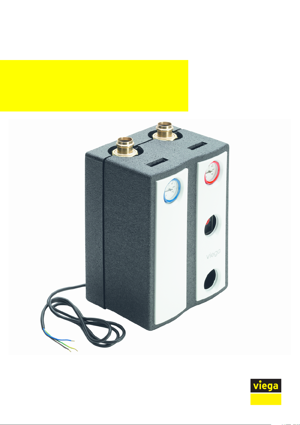
Compact control station preset value
Instructions for Use
for Fonterra radiant heating and cooling, central regulation of
the supply temperature of several manifolds
Model Year built:
1252.1 from 01/2012
en_INT
Page 2

Compact control station preset value 2 from 11
Page 3

Table of contents
1 About these instructions for use 4
Table of contents
1.1
1.2
1.3
Target groups 4
Labelling of notes 4
About this translated version 5
2 Product information 6
2.1
2.1.1
2.2
2.2.1
2.2.2
Intended use 6
Areas of use 6
Product description 6
Overview 6
Technical data 7
3 Handling 8
3.1
3.1.1
3.1.2
3.2
3.2.1
3.3
3.3.1
3.4
Assembly information 8
Installation dimensions 8
Change supply and return flow section 8
Assembly 10
Wall mounting 10
Control 11
Setting the underfloor supply temperature 11
Disposal 11
Compact control station preset value 3 from 11
Page 4
About these instructions for use
1 About these instructions for use
Trade mark rights exist for this document, further information can be
found at
1.1 Target groups
The information in this instruction manual is directed at the following
groups of people:
n Heating and sanitary professionals and trained personnel
n Trained electricians
n Operators
It is not permitted for individuals without the abovementioned training or
qualification to mount, install and, if required, service this product. This
restriction does not extend to possible operating instructions.
viega.com/legal
.
1.2 Labelling of notes
The installation of Viega products must take place in accordance with
the general rules of engineering and the Viega instructions for use.
Warning and advisory texts are set aside from the remainder of the text
and are labelled with the relevant pictographs.
DANGER!
This symbol warns against possible life-threatening injury.
WARNING!
This symbol warns against possible serious injury.
CAUTION!
This symbol warns against possible injury.
NOTICE!
This symbol warns against possible damage to property.
Notes give you additional helpful tips.
Compact control station preset value 4 from 11
Page 5

1.3 About this translated version
This instruction for use contains important information about the choice
of product or system, assembly and commissioning as well as intended
use and, if required, maintenance measures. The information about the
products, their properties and application technology are based on the
current standards in Europe (e. g. EN) and/or in Germany
(e. g. DIN/DVGW).
Some passages in the text may refer to technical codes in Europe/
Germany. These should serve as recommendations in the absence of
corresponding national regulations. The pertinent national laws, standards, regulations and guidelines, as well as other technical guidelines,
have priority over German/European guidelines in this manual: The
information is not binding for other countries and territories and should,
as mentioned, be considered as support.
About these instructions for use
Compact control station preset value 5 from 11
Page 6

2 Product information
2.1 Intended use
2.1.1 Areas of use
Use the compact control station in heating systems where on the one
hand their heat output takes place with a high supply temperature (e. g.
radiators, heating ventilators or similar) and on the other hand through
low-temperature heat surfaces (e. g. underfloor or wall heating).
The compact control station has a mixer valve for regulating fixed
values without auxiliary energy.
NOTICE!
This manual as well as the documents supplied about the
circulation pump and the 3-way regulating valve are part of
the product and must be observed and kept.
Product information
2.2 Product description
2.2.1 Overview
NOTICE!
Alterations or changes not in compliance with the intended
use are not permitted and will invalidate the warranty.
Fig. 1: Component overview, plan view
1 - wall bracket
2 - rear part insulating shell
3 - control station
4 - front part insulating shell
Compact control station preset value 6 from 11
Page 7

2.2.2 Technical data
Product information
Maximum permitted operating
95 °C
temperature
Minimum permitted operating
-20 °C
1)
temperature
Maximum permitted operating
1 MPa (10 bar)
pressure
Nominal heating capacity 15 kW
1)
with anti-freeze added, max. 40 % per cent by volume.
With fluid temperatures below 20 °C, take potential condensation into
consideration. Furthermore, use suitable cooling media if the temperature of the media drops below the water freezing point.
Materials
Fittings Pressed brass Ms 58
Pipe runs Precision pipes
Thermal insulation shell EPP
Handles Fibre-glass reinforced, tempera-
ture-resistant plastics
O-rings EPDM elastomers
Flat seals AFM 34 or EPDM elastomers
Valve seats PTFE
Compact control station preset value 7 from 11
Page 8

3 Handling
3.1 Assembly information
3.1.1 Installation dimensions
Handling
Fig. 2: Casing and connection dimensions
Height (with insulation) approx. 344 mm (355 mm)
Width with insulation approx. 250 mm
Axis distance approx. 125 mm
Connections
1)
Sanpress enclosed
3.1.2 Change supply and return flow section
The compact control station factory-fitted with the supply on the righthand side and the return flow on the left-hand side. If it is necessary for
the installation situation, you can change the lines.
This is how you change the supply and return flow lines on the compact
control station:
Rotate the whole group by 180°.
G1½ x 28
1)
Compact control station preset value 8 from 11
Page 9

Remove the caps (B) as well as the connecting pipe (C).
Loosen the pump screw fitting (D) as well as the return flow ball
valve screw fitting (E).
Handling
Rotate the pump with supply ball valve and return flow ball valve by
180°.
Re-tighten screw fittings (D) and (E).
Re-mount the cap (B) as well as the connecting pipe (C).
Compact control station preset value 9 from 11
Page 10

Handling
Open the adjustment wheel of the 3-way valve as far as it will go
anti-clockwise.
Using a screwdriver, remove the adjustment wheel gently and place
it in a new position, so that the number 6 points towards the triangular marking
Set the valve to the desired position.
Check the supply temperature with a thermometer.
Change the EPP bracket of the return flow pipe from left to right.
NOTICE!
If the compact control station is rotated by 180°, you must
place the opening for the mixer (approx. 53 mm) on the lefthand side. In addition, remove the inserted insulating shell
for the return flow pipe from the left-hand side out of the
insulating box and re-insert it on the right-hand side.
3.2 Assembly
3.2.1 Wall mounting
NOTICE!
In the case of the compact control station model 1252.1 our
settings are valid as opposed to the manufacturer's information. Manufacturer's documentation should be observed
regarding maintenance and repairing faults.
Fig. 3: Specified spaces for wall mounting
How to mount the compact
control station to the wall:
Compact control station preset value 10 from 11
Page 11

Handling
Use the wall bracket to perforate the pre-formed slits in the rear part
of the heat insulation from the front.
Place the wall bracket to the wall (opening pointing up) and fasten it
with dowel and screws.
Clip in the rear part of the heat insulation. Insert the hexagonal profile of the ball valves in the hexagonal profile of the wall bracket.
Connect to the boiler / heating circuit.
Have an authorized technician connect the pump.
Fill the system and perform a leakage test. Ensure that all the air is
flushed out of the system.
If required, ventilate the pump separately.
Set the 3-way valve to the desired supply temperature. Use the ther-
mometer to check the supply temperature.
Pull the rear part of the heat insulation towards the station and clip
in the front part of the heat insulation.
3.3 Control
3.3.1 Setting the underfloor supply temperature
If maximum power (nominal power) is required, set the boiler supply
temperature at least 15 °C higher than the desired supply temperature
in the underfloor circuit.
The setting handwheel of the mixer valve has a scale of 1 to 6 and
allows for continuous setting of a supply temperature between 15 and
55 °C. Refer to the table below for the respective target temperature:
Scale value
Target temperature in °C 15 27 32 37 48 55
The recommended setting range for underfloor heating is
level 3–6 (32–55 °C).
1 2 3 4 5 6
3.4 Disposal
Separate the product and packaging materials (e. g. paper, metal,
plastic or non-ferrous metals) and dispose of in accordance with valid
national legal requirements.
Compact control station preset value 11 from 11
 Loading...