

Page 1
Basic unit 24 V
with pump module
Instructions for Use
for Fonterra radiant heating and cooling, max. 6 room thermostats, max. 12 heating circuits
Model Year built:
1247.4 from 01/2007
en_INT
Page 2

Basic unit 24 V
with pump module 2 from 17
Page 3

Table of contents
1 About these instructions for use 4
Table of contents
1.1
1.2
Target groups 4
About this translated version 4
2 Product information 5
2.1
2.2
2.3
2.3.1
2.3.2
2.3.3
2.3.4
Safety advice 5
Intended use 5
Product description 5
Functions 5
Overview and description of component 6
Technical data 8
Accessories 8
3 Handling 10
3.1
3.2
3.3
3.3.1
3.3.2
3.4
3.4.1
3.4.2
3.4.3
3.4.4
3.4.5
3.5
3.6
3.7
Transport and storage 10
Preconditions for installation 10
Assembly 10
Assembly sequence 10
Mounting the basic unit 11
Commissioning 12
Making the electrical connection 12
Connecting the actuators 12
Connecting the room thermostat 14
Connecting an external time switch 15
Connecting the pump 16
Troubleshooting 16
Care tips 17
Disposal 17
Basic unit 24 V
with pump module 3 from 17
Page 4

About these instructions for use
1 About these instructions for use
Trade mark rights exist for this document, further information can be
found at www.viega.com/legal-notices.
1.1 Target groups
The information in this instruction manual is directed at the following
groups of people:
n Heating and sanitary professionals and trained personnel
n Trained electricians
n Operators
It is not permitted for individuals without the abovementioned training or
qualification to mount, install and, if required, service this product. This
restriction does not extend to possible operating instructions.
The installation of Viega products must take place in accordance with
the general rules of engineering and the Viega instructions for use.
1.2 About this translated version
This instruction for use contains important information about the choice
of product or system, assembly and commissioning as well as intended
use and, if required, maintenance measures. The information about the
products, their properties and application technology are based on the
current standards in Europe (e. g. EN) and/or in Germany
(e. g. DIN/DVGW).
Some passages in the text may refer to technical codes in Europe/
Germany. These should serve as recommendations in the absence of
corresponding national regulations. The pertinent national laws, standards, regulations and guidelines, as well as other technical guidelines,
have priority over German/European guidelines in this manual: The
information is not binding for other countries and territories and should,
as mentioned, be considered as support.
Basic unit 24 V
with pump module 4 from 17
Page 5

2 Product information
2.1 Safety advice
DANGER!
Danger due to electrical current
An electric shock can lead to burns and serious injury and
even death.
– Work on the electrics may only be carried out by trained
electricians.
– Switch off the mains voltage before carrying out work on
electrical parts.
– Switch off the mains voltage before opening the casing.
Product information
2.2 Intended use
2.3 Product description
2.3.1 Functions
You can use the basic unit 24 V for electronic control of your surface
heating. The basic unit converts the information by the connected room
thermostats to control signals for the actuators.
This function is guaranteed in combination with:
n
room thermostat model 1243.1 or 1243.4
n and actuator model 1249.1
The basic unit controls all functions of the system and converts the
measured value transmitted by the room thermostat to control signals
for the actuators. For the operation of the basic unit, a 230 V mains connection must be provided in the manifold cabinet.
To ensure proper functionality of the pump control, actuators with the
property "closed in de-energised state " are required.
The basic unit is connected to the mains by means of a separately available power pack (model 1247.5)
verts the 230 V mains voltage to 24 V.
Ä „Power pack“ on page 9
which con-
All actuators and room thermostats connected via cable are directly
supplied with the required operating voltage. Additional mains connections are not required.
Basic unit 24 V
with pump module 5 from 17
Page 6
②
③
④
⑤
⑥
⑦
①
Features
Product information
n Simple plugging / clamping solution
n Connections per room thermostat (zone)
– 2 actuators (standard)
– 4 actuators (optional, max. 2 x)
n Connection for control of one circulation pump
n Connection for one external time switch
n Connection for room thermostats with time switch
Optionally, you can transmit the signal of the room thermostat to two other actuators (terminal 2 and/or 5) at terminal 1
and/or 4. In this case, one thermostat each in total can be
used.
System components required
For using the single room regulation in combination with a basic unit,
please order the specified number of the following components in addition:
n
room thermostats – model 1243.1 (analogue) or 1243.4 (digital)
n actuators – model 1249.1
n power pack – model 1247.5
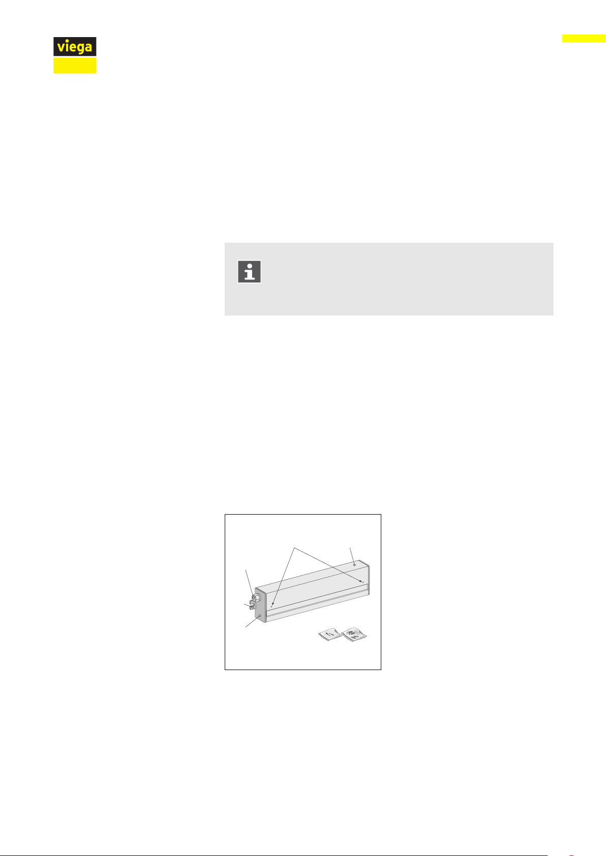
2.3.2 Overview and description of component
Scope of delivery
Fig. 1: Basic unit
1 - holding screws casing cover
2 - casing cover
3 - fixing material casing
4 - casing screws
5 - casing
6 - fixing lugs
7 - cable inlet
Basic unit 24 V
with pump module 6 from 17
Page 7

① ②
③
⑥ ⑤ ④
Installation dimensions
Product information
Fig. 2: Basic unit
Terminal diagram
Fig. 3: Basic unit, terminal assignment
1 - fuse
2 - room thermostat terminals
3 - actuator terminals
4 - pump control terminals (only with model 1247.3 and 1247.4)
5 - external time switch terminals
6 - 24 V terminals
CAUTION!
Cable breakage due to tensile strain
– The strain relief devices are designed for 5 x 1.5 mm
cables.
For other cable cross-sections, mount the appropriate
strain relief device.
2
Basic unit 24 V
with pump module 7 from 17
Page 8

2.3.3 Technical data
Operating voltage 24 V AC
Max. wattage max. 50 W
Switching voltage pump 230 V
Switching current pump 5 A
Fuse T 2A
Max. no. of room thermostats 6
Max. no. of actuators 12
Heating programs - optional 2
Protection class II
Degree of protection IP20
Product information
CE conformity EN 60730
Ambient temperature 0–60 °C
Storage temperature range -25–65 °C
Relative humidity – non-condensing ≤ 80 %
Dimensions H / W / D 75 / 40 / 325 mm
Weight 350 g
Usable line cross-sections (terminals)
1.5 mm2 (solid line)
2.3.4 Accessories
Actuator
Electrically operated valve for regulating the heating water volume flow
in the heating circuit.
Actuator "closed in de-energised state", 24 V – model 1249.1
Fig. 4: Actuator
Basic unit 24 V
with pump module 8 from 17
Page 9

Room thermostat
Product information
Transmits the required measuring values to the basic unit for regulating
the heating circuits via a cable connection:
Room thermostat, analogue 24 V – model 1243.1
Fig. 5: Room thermostat analogue
Fig. 6: Room thermostat digital
Power pack
Room thermostat, digital 24 V with electronic week time switch –
model 1243.4
For connection to basic units with 24 V operating voltage to 230 V
mains supply.
Power pack – model 1247.5
Fig. 7: Power pack
Basic unit 24 V
with pump module 9 from 17
Page 10

3 Handling
3.1 Transport and storage
Observe the following with transport and storage:
n Avoid heavy blows and vibrations.
n Store components in a clean and dry place.
n Do not remove the components from the packaging until immedi-
Handling
ately before use.
NOTICE!
Replace defective components, do not repair.
3.2 Preconditions for installation
A power pack provides 24 V operating voltage to the basic unit. For
operation, the customer must provide a 230 V socket in direct vicinity of
the manifold.
3.3
3.3.1 Assembly sequence
Assembly
To assemble the components, proceed as follows:
n
Mount the room thermostats.
n Mount the actuators on the manifold.
n Mount the basic unit.
n Mount the power pack.
n Connect the cables of the room thermostat and the actuators with
the basic unit.
n Establish the power supply / commission.
Basic unit 24 V
with pump module 10 from 17
Page 11

3.3.2 Mounting the basic unit
Mounting preparation
n The manifold and actuators have been mounted.
n The power supply for the basic unit has been prepared.
n The room thermostats have been mounted and connected.
Required tools and materials:
n Power drill
n Ø 6 mm masonry drill, or Ø 3 mm metal drill for mounting the basic
n Screwdriver
n Two dowels 6 x 30 and screws for wall mounting are comprised in
n Cables in sufficient length for connecting the room thermostats
Handling
unit to the rear of the manifold cabinet.
the scope of delivery.
NOTICE!
The installation site must be in direct vicinity of the manifold.
Make bore holes spaced at 310 mm.
Use the supplied screws and dowels to mount the basic unit to the
wall.
Basic unit 24 V
with pump module 11 from 17
Page 12

3.4 Commissioning
65
75
70
3.4.1 Making the electrical connection
Generating power supply with a power pack
DANGER!
Risk of electric shock
An electric shock can lead to burns and serious injury and
even death.
– Work on the electrics may only be carried out by trained
– Always de-energise the connection line before work is
Use the enclosed holder and fixing material to mount the power
pack to the wall in the vicinity of the basic unit.
Handling
electricians.
commenced.
Maximum distance to the basic unit: 200 mm.
CAUTION! Risk of injury due to electrical current
– If the 230 V connection cable is defective, replace the trans-
former. Never attempt to repair the cable!
Loosen the fixing screws at the basic unit and remove the cover of
the casing.
Connect the power pack cables to the marked 24 V terminals.
Place the cover on the casing and screw it down.
3.4.2
Connecting the actuators
A maximum of twelve actuators can be connected to the basic unit.
By default, one or two actuators can be assigned to one room thermo-
stat. Optionally, you can transmit the signal of one room thermostat to
Basic unit 24 V
with pump module 12 from 17
two actuators
Ä „Assigning four actuators to one RT“ on page 13
Page 13

Assigning two actuators to one RT
Assigning four actuators to one RT
Handling
Loosen the fixing screws and remove the cover of the casing.
Break off the pre-cut cable inlet in the area of the connection ter-
minal at the bottom of the casing.
Insert the strain relief device provided by the customer.
Connect the leads of the cable pursuant to the terminal diagram.
Close the casing cover.
NOTICE!
Optionally, you can transmit the signal of the room thermostat to two other actuators (terminal 2 and/or 5) at terminal 1
and/or 4. In this case, one thermostat each in total can be
used.
Break off the pre-cut cable inlet in the area of the connection terminal at the bottom of the casing.
Insert the strain relief device provided by the customer.
Connect the leads of the cable pursuant to the terminal diagram.
Close the casing cover.
Basic unit 24 V
with pump module 13 from 17
Page 14

3.4.3 Connecting the room thermostat
The cable is fed through the pre-cut openings in the casing. Strain relief
devices matching the cables used must be provided by the customer.
Loosen the fixing screws and remove the cover of the casing.
Break off the pre-cut cable inlet in the area of the connection ter-
minal at the bottom of the casing.
Insert the strain relief device provided by the customer.
Bare the leads of the cable over a length of 10 mm or use cable
sleeves, and connect them pursuant to the terminal diagram.
Close the casing cover.
Handling
Connecting the room thermostat with time switch
Loosen the fixing screws and remove the cover of the casing.
Break off the pre-cut cable inlet in the area of the connection ter-
minal at the bottom of the casing.
Insert the strain relief device provided by the customer.
Bare the leads of the cable over a length of 10 mm or use cable
sleeves, and connect them pursuant to the terminal diagram.
Close the casing cover.
Basic unit 24 V
with pump module 14 from 17
Page 15

3.4.4 Connecting an external time switch
Time switch with two switching signals – A or B.
CAUTION!
Risk of damage due to incompatible time switches
The connection of an unsuitable time switch may result in
malfunction and cause damage to the control.
– Only connect time switches with floating contact.
Loosen the fixing screws and remove the cover of the casing.
Break off the pre-cut cable inlet in the area of the connection ter-
minal at the bottom of the casing.
Insert the strain relief device provided by the customer.
Bare the leads of the cable over a length of 10 mm or use cable
sleeves, and connect them pursuant to the terminal diagram.
Handling
Assigning the time switch signal
Close the casing cover.
Connect the switching signal A or B with the timer signal (lowering
channel) of a room thermostat.
Loosen the fixing screws and remove the cover of the casing.
Break off the pre-cut cable inlet in the area of the connection ter-
minal at the bottom of the casing.
Insert the strain relief device provided by the customer.
Bare the leads of the cable over a length of 10 mm or use cable
sleeves, and connect them pursuant to the terminal diagram.
Close the casing cover.
Basic unit 24 V
with pump module 15 from 17
Page 16

3.4.5 Connecting the pump
Handling
Loosen the fixing screws and remove the cover of the casing.
Break off the pre-cut cable inlet in the area of the connection ter-
minal at the bottom of the casing.
Insert the strain relief device provided by the customer.
Bare the leads of the cable over a length of 10 mm or use cable
sleeves, and connect them pursuant to the terminal diagram.
Close the casing cover.
–
The signal is issued by the basic unit.
–
If no controller requests heat, the pump switches off.
–
The pump must be externally connected to the mains.
3.5 Troubleshooting
Check the fuse, replace if necessary
DANGER!
Risk of electric shock from 230 V voltage!
Risk of electric shock when working at the open casing or at
cable inlets.
– Commission a qualified contractor to carry out the work
if you need to open the casing or repair cables in the
course of troubleshooting.
The fuse protects the basic unit from overvoltage from the mains. If the
control acts differently than expected during operation, check the fuse
first.
Loosen the fixing screws and remove the cover of the casing.
Remove the fuse and replace if with a new one.
Fuse type: T 2A H
Place the cover on the housing and screw it down.
Basic unit 24 V
with pump module 16 from 17
Page 17

3.6 Care tips
3.7 Disposal
Handling
The surfaces of the control elements are made of premium materials
and require little care. When cleaning the elements, bear in mind that
the devices are live. Make sure that no water gets into the casing.
Care tips
n Wipe the surfaces down with a moist cloth.
n Remove coarse dirt with a mild soap solution.
n Do not use aggressive or scouring detergents.
Separate the product and packaging materials (e. g. paper, metal,
plastic or non-ferrous metals) and dispose of in accordance with valid
national legal requirements.
Basic unit 24 V
with pump module 17 from 17
 Loading...