

Vido.at AU-G35M-SB18, AU-G35M-SC18, AU-G35M-SB26, AU-G35M-SB36, AU-G35M-SB26WD User Manual
...Page 1
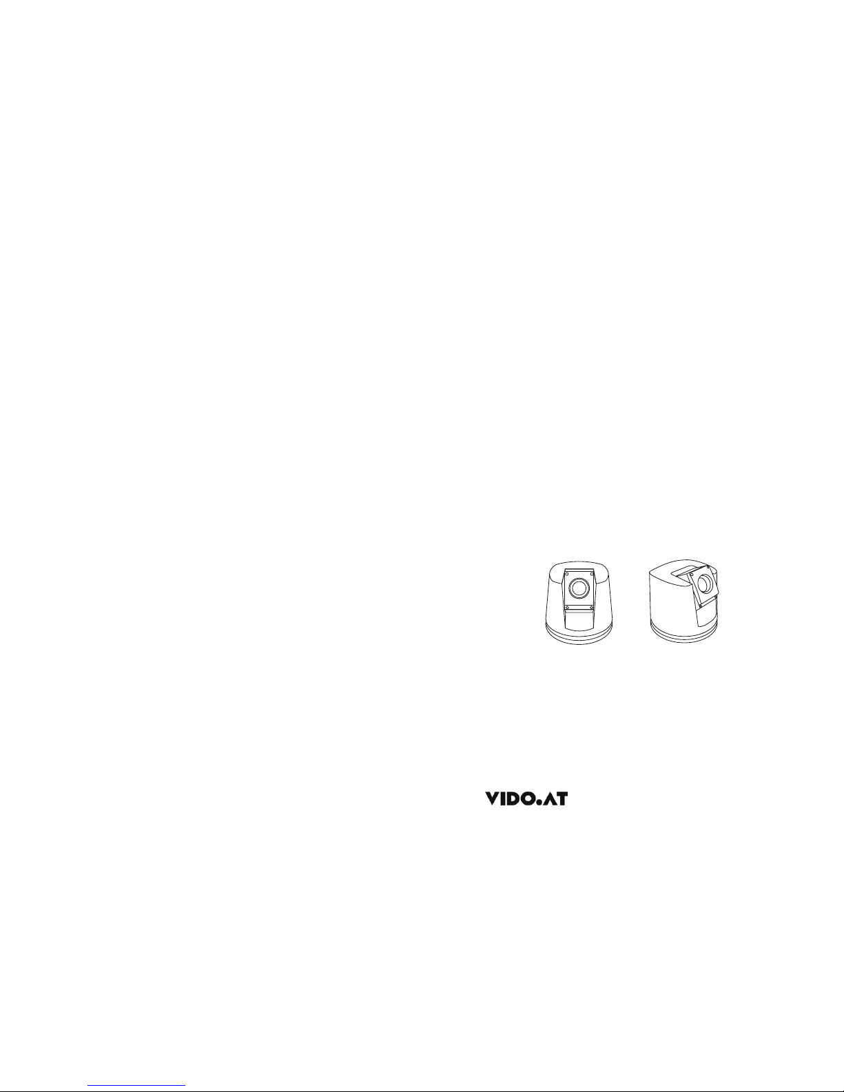
AU-G35M
USER'S MANUAL
v1.0
Mobile PTZ Camera Series
www.vido-europe.com
Preliminary
Page 2
CONTENTS
TO REDUCE THE RISK OF FIRE OR ELECTRIC SHOCK, DO NOT EXPOSE THIS PRODUCT TO RAIN
OR MOISTURE.DO NOT INSERT ANY METALLIC OBJECTS THROUGH THE VENTILATION GRILLS OR
OTHER OPENINGSON THE EQUIPMENT.
FCC COMPLIANCE STATEMENT
CE COMPLIANCE STATEMENT
CAUTION: CHANGES OR MODIFICATIONS NOT EXPRESSLY APPROVED BY THE PARTY
RESPONSIBLE FORCOMPLIANCE COULD VOIDTHE USERS‘S AUTHORITY TO OPERATE THE
EQUIPMENT.
FCC INFORMATION: THIS EQUIPMENT HAS BEEN TESTED AND FOUND TO COMPLY WITH THE
LIMITS FOR A CLASS A DIGITAL DEVICE, PURSUANT TO PART 15 OF THE FCC RULES. THESE
LIMITS ARE DESIGNED TO PROVIDE REASONABLE PROTECTION AGAINST HARMFUL
INTERFERENCE WHEN THE EQUIPMENT IS OPERATED INA COMMERCIAL ENVIRONMENT. THIS
EQUIPMENT GENERATES, USES, AND CAN RADIATE RADIO FREQUENCY ENERGY AND IF NOT
INSTALLED AND USED IN ACCORDANCE WITH THE INSTRUCTION MANUAL, MAY CAUSE
HARMFUL INTERFERENCE TO RADIOCOMMUNICATIONS. OPERATION OFTHIS EQUIPMENT IN A
RESIDENTIAL AREA IS LIKELYTO CAUSE HARMFUL INTERFERENCE IN WHICH CASE THE USER
WILL BE REQUIREDTO CORRECT THE INTERFERENCE AT HIS OWN EXPENSE.
WARNING: THIS IS A CLASS A PRODUCT. IN A DOMESTIC ENVIRONMENT THIS
PRODUCT MAY CAUSE RADIO INTERFERENCE IN WHICH CASE THE USER MAY BE
REQUIRED TO TAKE ADEQUATE MEASURES.
CAUTION: TO REDUCETHE RISK
OF ELECTRICSHOCK, DO NOT
REMOVE COVER( OR BACK).NO
USER SERVICEABLEPARTS
INSIDE. REFERSERVICING TO
QUALIFIED SERVICE
PERSONNEL
This symbolindicates that dangerous
voltage constitutinga risk ofelectric
shock ispresent within thisunit.
This symbolindicates that thereare
important operatingand maintenance
instructions inthe literature
accompanying thisunit.
WARNING
CAUTION: BEFOREATTEMPTING TO CONNECTOR OPERATE THIS PRODUCT, PLEASE
READ THE LABEL ON THE BOTTOM AND USER'S MANUAL CAREFULLY
1. Precaution......................................................1
2. Features.........................................................2
3. Packing list.....................................................3
4. Installation...................................................... 4
5. Operation........................................................10
6. OSD................................................................11
7. Adress and Protocol Setting...............................19
8. Specifications..................................................23
Technical specification are subjects to change without
prior notice. Manual may contain mistake or print error.
All trademarks mentioned belong to their respective owners.
ENGLISH
Page 3
1.PRECAUTION
Refer all work related to the installaion of this product to qualifiedservice
personnel or system installers.
Do not attemp to disassemble the appliance
Handle the appliance with Care
Do not use strong or abrasive detergents whencleaning the appliance body and
transparent cover.
Do not operate the apliance beyond its specified temperature, humidity or power
source ratings.
Do not point the camera lens directly to sunlight or any stronglight source.
Read this user's manual carefully before operating the appliance.
Do not install the camera in other orientation as designed.
Do not touch the Cover with bare hands or any object.
To prevent electric shock, do not remove screws or cover. There are no userserviceable parts inside. Contact qualified service personnel for maintenance
Do not strike or shake, as this may damage the appliance. Itshould be protected
against extreme pressure, vibration and humidity during transportation and storage.
Damages caused by improper transportation avoid the warranty.
Use a dry cloth to clean the appliance when it is dirty. When the dirt is hardto remove,
use a mild detergent and wipe gently.
Do not use the dome camera in an extreme environment where hightemperature or
high humidity exists.
Take immediate action when the indoor speed dome becomes wet. Turn off the power
and refer servicing to qulified service personnel. Moisture may damage the appliance
and cause eletric shock.
This will cause permanent damage to the cameraand avoids the warranty.
Make sure that local electric safty standard are followed when using orinstalling the
appliance
And do not bend or squeez the sturctiure, as this may damagethe mechanic sturcture
of the appliance and avoids the warranty.
These will scratch the serface and affect the image qulaity.
Use the within -20°C to +60°C(-4°F to 140°F) and a humidity below
90%. The input power source is 12V DC, 50/60Hz and requires 2000mA.
outdoor models
Do not expose the indoor model of dome camera to water ormoisture, not try to
operate it in wet areas.
2.FEATURES
The G35M are
The integrated, motorized pan-tilt mechanic allows user to point
the camera to any position( 360° horizontal and 120° vertical). This series can be
equipped with digital zoom camera modules, which provide zooming functon from 18 to
36 times (optical) and advanced image features.
- 360° Pan and 120° Tilt range ( )
- Support most well-known camera modules
- 128 preset points memory
- 4 pattern tours
-4Scantour
- Basic setup directly from Keyboard.
- Advanced setup through OSD (On Screen Display) menu.
- up to 24 privacy masking zones ( despends on camera module)
- 7 alarm input & 2 output(4input&1outputpre-wired)
- Multi-Protocol through Rs485 or coaxial cable.
- Dirction Indicator on screen
- Aluminum Alloy structure with high intensity and heat-sinking
- High-precision step-motor for flicker-less image during movement.
-Shock resistance up to 10G
Wide-Range voltage input tolerance from 9 to 15V DC
-HighResolution with 520TVL and Wide-Dynamic*
- Auto-Focus
- Auto-Iris
- Auto- Brightness control,
- Auto-Balance
- IR cutter control, Day-Night mode switching.
- Auto Slow-Shutter
-Optional WDR or Electronic Image Stabilzer*
depends on camera module type.
Key features:
Camera Features:
*
Temperature monitoring and protection
Other features:
- Alarm notification will be displayed once the inner temperature exceeds the limit
- In low temperature area, the dome camera will only start afterthe operation
temperature is reached.
- Cooling fan activity is managed by the CPU ( extends theduration)
- Proportional pan for Focus / Speed on different zoom factor.
- Auto-resuming user-defined action, such as tour, pattern or scan after selectable idle
time.
- Power-up Action activates tour or pattern by default.
mobile PTZ camera series designed for vehicle and outdoor video
surveillance application.
-30° to +90°
-
12
ENGLISH
Some productsmay not beavailable in yourcountry, pleasecontact our distributorfor more details Some productsmay not beavailable in yourcountry, please contact our distributorfor more details
Page 4
3.PACKING LIST
Safety Instructions before starting
- Do not install and operate this appliance in a flammable and explosive environment.
- Make sure that the installation is done according to the local electricity safety regulation
of your country.
.
- Before installation and mentainence, make sure that the appliance is disconnected
from the power source.
- Do not use any power source other than 15V DC, inorder to prevent damages tothis
device. For details, please refer to the section "Precaution" in previous chapter for
more details.
- Handle the device during the installation carfully. Falls or extreme vibration may cause
irrepairable damages and avoid the warranty.
- Do not install or operate the appliance near any high-voltage devicesor high-voltage
cable. The safety distance should remain at least 50 m.
- To archive best image quality, its recommanded to use underground cable shielded with
steel tube. Do not install the cable without any protection.
- In a thunderstorm area or region with high inductive voltage, such as high voltage
transformer stations, it is necessary to use additional lighning-proof equipments or
lightning rob for protection.
- For outdoor installation, lightning-proof and grounding of the device should be
considered. Please refer to the industrial saftey regulation and request of your country
.
- Grounding of the appliance should consider anti-interference and fulfill the saftey
requirements. Do not connect the ground with short-circuited or other high-voltage
electric network.
- The resistance of down conductor should not exceed 4 Ohm, and its thickness should
be at least 25mm²
- This appliance has the lightning-proof function which can prevent damages caused by
high-voltage pulse, such as lightning strike below 1500.
- This appliance meets the Ip66 standard for water and dust proof. Do not install the indoor model for out-door application which is not designed with water protection.Make
sure that the installation is protected from long-time water-drop or spatter, which may
damage the appliance.
- Make sure that the enviroment of installation meets the requirement of the appliance,
such as holding the weight, enough spaces for bracket and power supply.
4.INSTALLATION
G35M
G35M
PTZ Camera
AU-G35M
USER'SMANUAL
www.vido-europe.com
Instruction and
operation manual
1 piece
Some modelsmay not beavailable in yourcountry, pleasecontact VIDO distributorfor more details
3
4
ENGLISH
Some productsmay not beavailable in yourcountry, pleasecontact our distributorfor more details
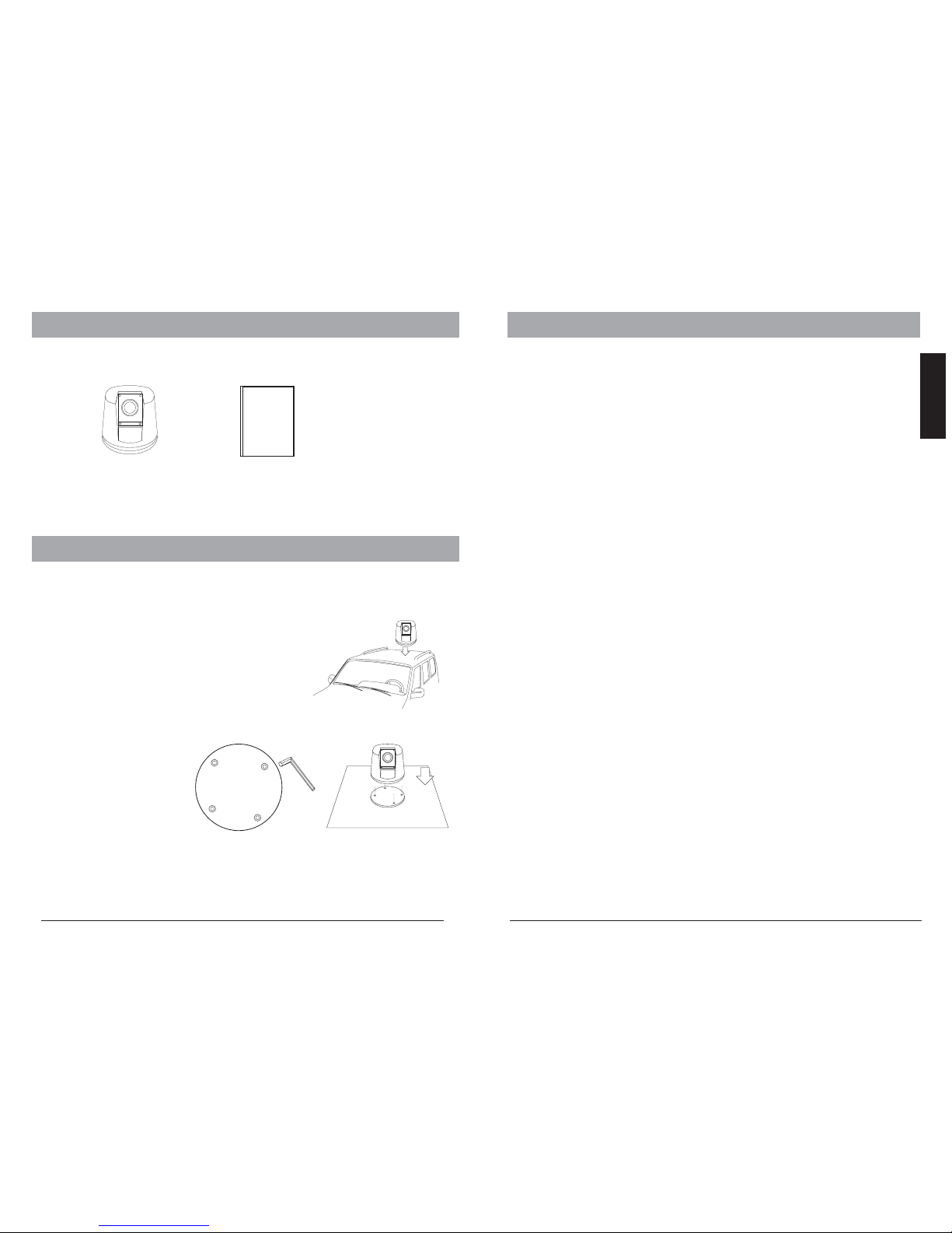
4.INSTALLATION
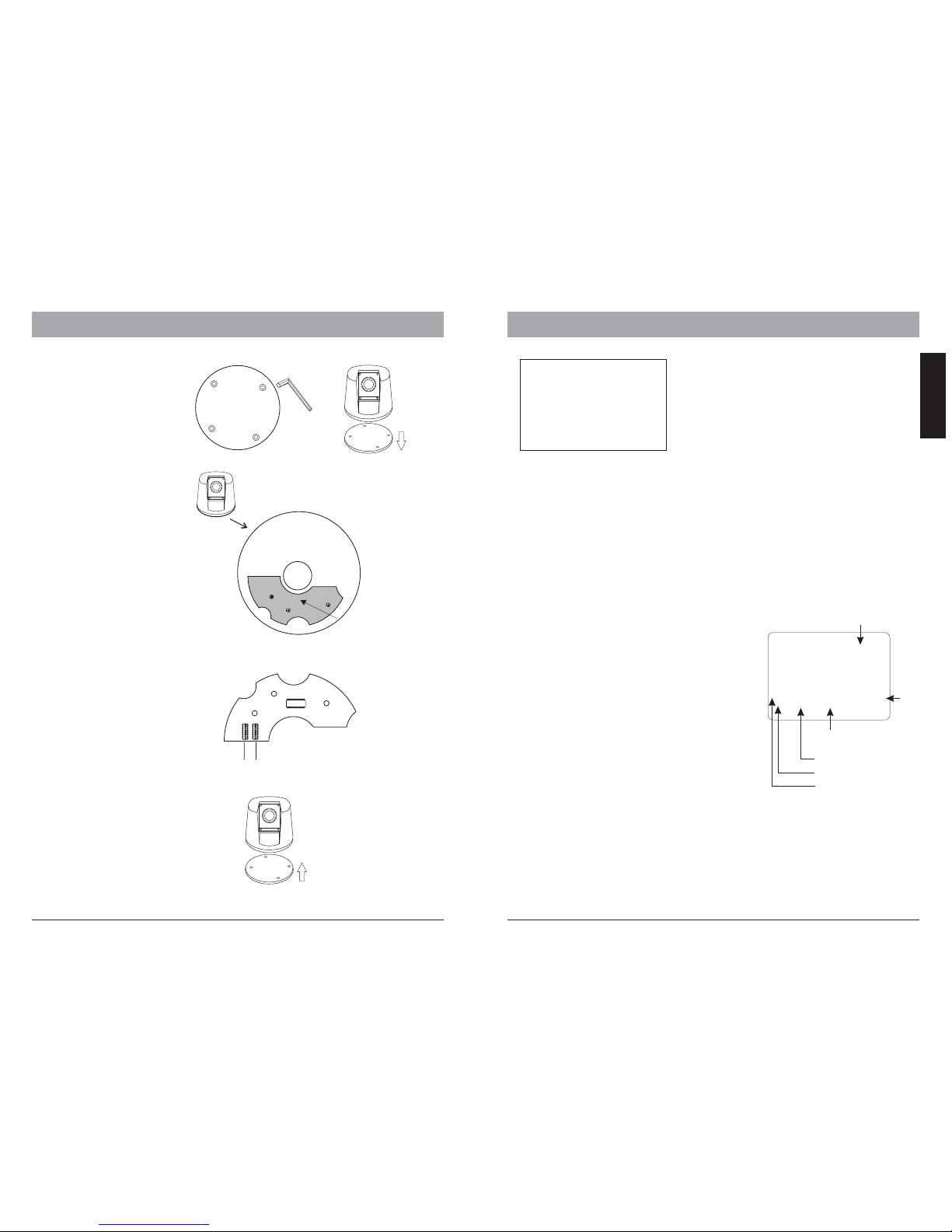
OpenthechassisofPTZ
camera withwrench. Fix the
base onthe vehicle with4
screws.
Installing G35M
Install thePTZ camera atthe top ofvehicle.
Page 5
4.INSTALLATION
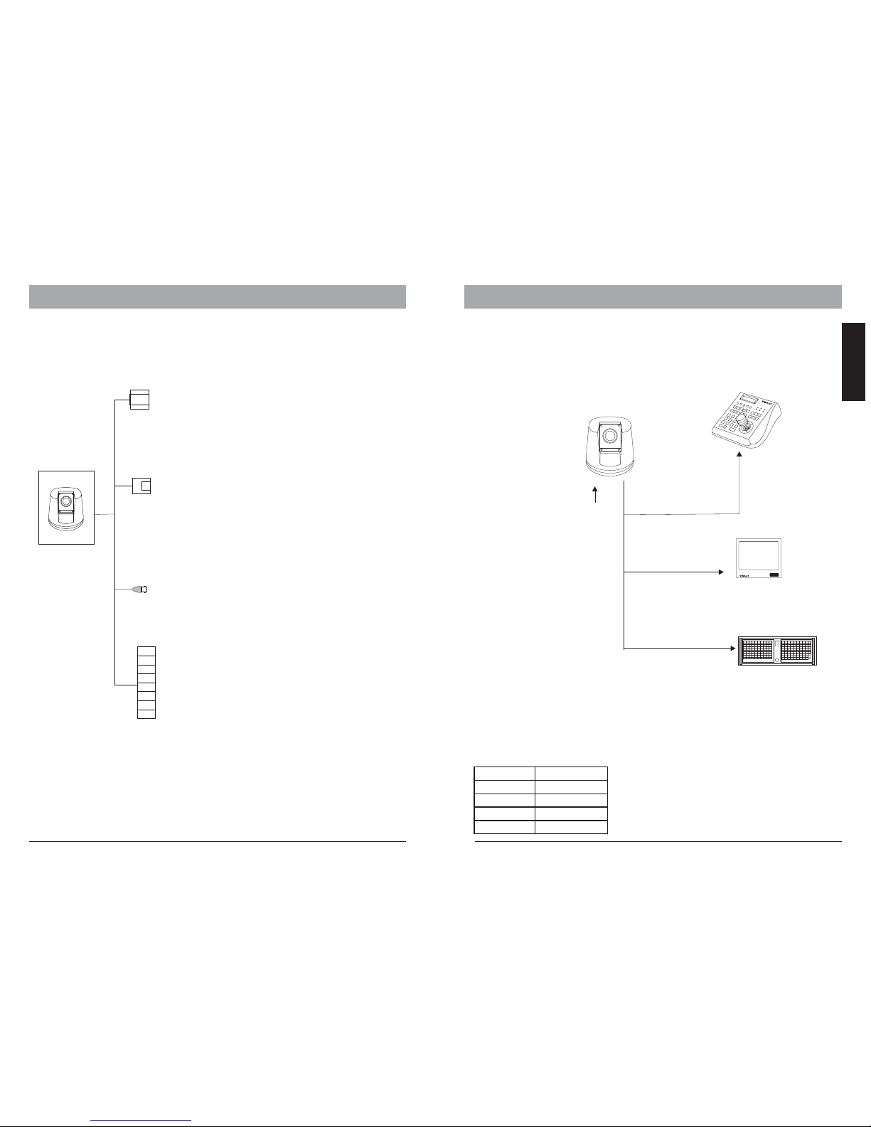
Connector description
The wiring cable of G35M series provides connectors for power supply, video andI/O
interface
Video output
BNC
Inner Conn: Signal +
Outer Conn: Ground
Video Output to monitor or DVR
Using optional accessories
The G35M series can be connected to various optional accessories through the
standard connector types, which simplifiy the cable handling and avoids possible
mistakes. All accessories are tested for max. compatibility and best performance.
DC 12V
Power input
AU-KB3N
3-Axis keyboard
controller
RS 485
Telemetriccontrol
camera setup
Monitor
BNC videoinput
DVR
Video signal
RS 485 cable
The telemetric control of the appliance uses Rs485 serial communication with halfduplex transmission technology.
Depends on the cable typeand baud rate, the transmission distance could vary. The
following table shows max. distances based on cable with 0,56mm (24AWG) twisted
pair:
2400 bps
1100 m
700m
4oom
4800 bps
1700m
9600 bps
19200 bps
Baud Rate
Max. Distance
Due theenvironmental interferences, suchas
eletromagnetic andinduction fields, ornumber of
connected applianceon the RS-485bus, the
transmission rangemay be less,e.g with cablethinner
than than 24AWG.
4.INSTALLATION
56
ENGLISH
KB3N
Power
Connector
RS485
Connector
RJ-11
Alarm I/O 1
RED: DC 12V +
BLACK: V -
To power supply
DC 12
Green:RS485+
Yellow:RS485-
To Keyboard or DVR decives for
telemetric control
RED: Alarm in 1
PINK: Alarm in 2
YELLOW:
GREEN:
BLACK: COM
WHITE: Alarm output - N.O
BLUE: Alarm output - N.C
Alarm in 3
Alarm in 4
I/O interface to additional alarm sensor
or control devices
Some productsmay not beavailable in yourcountry, pleasecontact our distributorfor more details Some productsmay not beavailable in yourcountry, pleasecontact our distributorfor more details
(power fromvehicle)
Page 6
4.INSTALLATION
4.INSTALLATION
Video Cable
coaxial cable with 75 impedance with copper conductor at center conductor, and
shielded with 95% copper. The following table shows different cable typeand its
maximum length:
Ω
The values are for reference only.
Depends on the cable quality and
environmental condition, the
transmission distance might be less.
RG6/U
Cable standard
RG 11 /U
229m /750 ft
Max. Distance (m /ft)
305m/ 1000ft
457m /1500 ft
RG 59/U
If the cable length is more than 400 m, it is recommended to use optional
accessories, such as video amlifier(e.g AU-VD-1001) or twisted-pair video
converter (e.g. AU-TP02 or AU-TP08), for boost the video signal.
AU-VD1001
VideoAmplifier
(optional)
AU-DVRN16/400
Realtime DVR Center
(optional)
AU-JD2102
HighRes Monitor
(optional)
Up to750m, coaxial cable
Extend connectiondistance with
video amplifier
AU-TP08
TPreceiver
(optional)
AU-DVRN16/400
Realtime DVR Center
(optional)
AU-JD2102
HighRes Monitor
(optional)
Up to1200m, twisted pairor cat.5 cable
Extend connectiondistance with Twisted-Pair
video converter
AU-TP02or
AU-TP08transmitter
(optional)
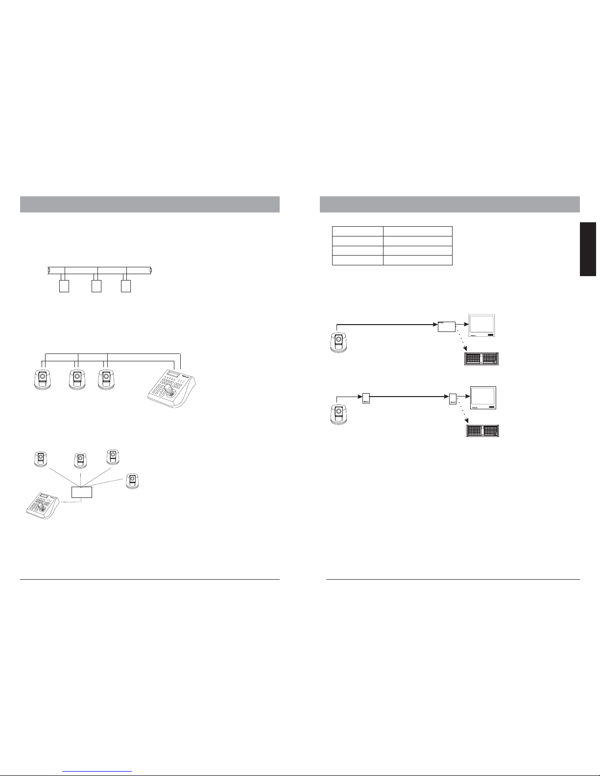
G35M provide integrated termination switch. It should be turned on when the dome
is installed as the last device. If the controller keyboard is used such asAU-KB3A,
you need also to turn on the termination on it. please refer to the keyboard’s
manual for details.
RS-485Termination
Devices using Rs485 control are usually connected in daisy-chain. which reqiuers
termination with 120 resistor on both ends. Following picture illustrates the
connection methods. please note that a daisy-chain connection type shall not
exceed 7 meters.
Ω
120
Ω
Resistor
Device 2 Device 3Device 1
120
Ω
Resistor
RS 485+
RS 485-
RS 485+
RS 485-
Termination
on
Termination
off
Termination
off
Star-Connection
The star-form connection is mostly used. it enables the connection of different dome
cameras in longer distance. It is recommended to use RS-485 distributor (e.g AU-VCMC2088) to ensure the telemetric data transmission:
The advantage of star-connection is
that every channel can work
independently and take a cable
length up to 1000 meters( depends
on cable quality). In case more
dome camera are installed, the starconnection can be extended with
additional RS-485 distributors.
Some productsmay not beavailable in yourcountry, pleasecontact our distributorfor more details Some productsmay not beavailable in yourcountry, pleasecontact our distributorfor more details
7
8
ENGLISH
Terminationon
AU-KB3N
KB3N
Terminationon
AU-KB3N
AU-MC2088
RS-485
Distributor
RS-485 cable
up to1000m
per channel
Termination
activated on
every end.
KB3N
Page 7
5.OPERATING THE SPEED DOME
FIRMWARE V1.0
Protocol: VIDOB02
Dome Address: 001
Comm 9600,N,8,1
Initial Screen
After powering up, the camera will enter the
self-test mode and display the status screen(
as in the picture left).It contains information
about the model and current settings.
- V1.0:
- Protocol:
- Dome address:
- Comm 9600,N,8,1:
Current firmware version
control protocol which currently used
Address ID of speed dome. please refer to the section "Protocol
setup " for details.
current setting of the serial communication interface.
Baud rate. please refer to section "Baud-Rate setup" for details
No parity bit, 8 bit length, 1 stop bit. this setting can not be changed
9600:
N, 8, 1:
Operation Screen
The intial screen will stay remain on until any user action isbeing taken. If the powerup action is set, the initial info wil vanish immediatly.
10.5CCAM TITLE
ZONE-1
285 78 18X
09/11/17
09:32:35
Pan degree
Zoom factor
Tilt degree
Zone description
Temperature
Date &Time
4.INSTALLATION
PTZ operation
For the surveillance operation, the dome can be controlled from a keyboard device
(e.g. AU-KB3N), Multiplexer or DVR through RS-485 Interface. Make sure that the
cable is connected and the settings (baud rate, Address ID and protocol) of both
keyboard and the dome are configured correctly. For more description about the PTZ
operation, please refer to the user’s manual of the keyboard.
Some productsmay not beavailable in yourcountry, pleasecontact our distributorfor more details Some productsmay not beavailable in yourcountry, pleasecontact our distributorfor more details
910
ENGLISH
The operation screen can display additional
information.
Temperature: current temperature inside the
speed dome( C or F)
Cam title: User definable camera title
Zone: Current zone name
Pan deg.: Pan angle, 0-359°
Tilt deg.: Tilt angle, 0-90°
Zoom Factor: Zoom factor
Date &Time: show date(
and time(HH:MM:SS)
Display of the information can be activate or
deactivate through the OSD menu. please refer to
the system setting for detais.
°°
YY/MM/DD)
the cur.
the cur.
DIP Setting
the detailof setting, pleasesee Page 20
OpenthechassisofPTZ
camera with wrench.
Sw1 Sw2
Use wrenchto remove the
connect board.On the backof
the board,there are two
switches.
SW1: represent the dome’s
address
SW2: protocol and baud rate
setting
the bottom of
the PTZ Camera
release
connect board
Installing
Lock theclassis, intalling thedome.
Page 8
OSD
OSD Menu
How tostart the OSDmenu
The G35MSeries are equippedwith new OSD-Menufunction. All operation functions and
camera relatedsettings can bechanged or modifiedhere. In orderto use theOSD function,
a telemetriccontroller device, suchas Keyboard, DVRor other deviceswith similiar function
is necessarilyrequired. please makesure that thedevice used isphysically connected tothe
dome properly, and all connection parameters areset correctly.
Tostart the OSDMenu, you needto press followingkey on thekeyboard:
With AU-KB2A or
With AU-KB3N or
In casea DVR isused for the OSD, select “goto preset 95” or 2 X“goto preset 9”.Please
refer tothe DVR’s operation manual for moredetails.
Note thatin some certainsituations, it isnot possible toenter the OSDmenu:
1. thedome is runningtour
2. performingPTZ operation
3. domeis receiving commandother than OSD-requestfrom the keyboard.
please stopthe operation andtry again.
2X
2X
Shot
9 5
Enter
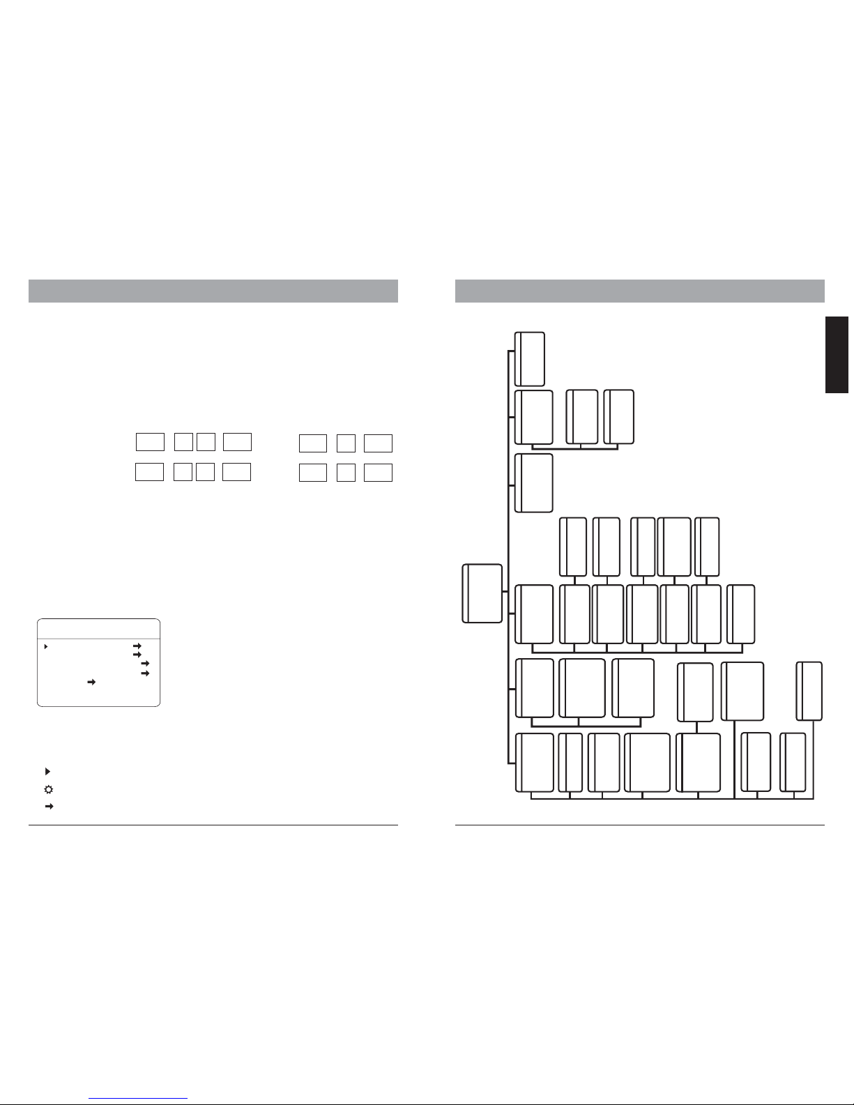
Main menu and navigation
Main Menu
SYSTEM SETTING
CAMERA SETTING
FUNCTION SETTING
WINDOW BLANKING
ALARM
EXIT
After enteringthe OSD Menu,the screen willshow menu
items .Use the controller’joystick to navigatethrough
the menu’s mainand sub itemsby moving inthe
direction. The angle mark onthe beginning ofevery
items indicatesthe selection.
UP, DOWN:- Moving betweencurrent menu items
- Changingthe value insubitems
RIGHT:- Enter theselected menu item
- Confirmthe value changeand return to
item selection
LEFT:Exit from submenu
For moreinforamtion, please referto the illustrationon
the nextpage for theOSD menu structure.
OSD-MAP
Symbols and indicator
Cursor.
Sub itemis selected. useup or downto change value
This itemhas subitem(s)
Some productsmay not beavailable in yourcountry, pleasecontact our distributorfor more details Some productsmay not beavailable in yourcountry, pleasecontact our distributorfor more details
call
9 5
Enter
call
9
Enter
Shot
9
Enter
ENGLISH
MAIN MENU
SYSTEM SETTING
CAMERA SETTING
FUNCTION SETTING
WINDOW BLANKING
ALARMS
LANGUAGE
EXIT
→
→
→
→
→
→
SYSTEM SETTING
EDIT DOME LABEL
INITIAL INFO
DISPLAY SETUP
MOTION
CLEAR
PASSWORDSETUP
CLOCKSETTING
BACK
EXIT
→
→
→
→
→
→
CAMERA SETTING
ZOOM SPEED HIGH
DIGITAL ZOOM ON
BLC MODE OFF
SLOW SHUTTER ON
LINESYNC N/A
WDR MODE N/A
ADVANCE SETTING 1 →
BACK
EXIT
ADVANCE SETTING 2
→
FUNCTION SETTING
IRCUTTER FILTER AUTO
IRCUT ONTIME
N
/A
IRCUT OFFTIME N/A
THRESHOLD
1
0dB
MAXGAIN
2
8dB
EXPOSURECOMP OFF
MIRROR
O
FF
FLIP OFF
SHARPNESS
0
0
BACK
EXIT
PRESETS
SCAN
SCAN NUMBER
0
1
SCAN SPEED
6
3
SET LEFT LIMIT
SET RIGHT LIMIT
CLEAR SCAN
RUN SCAN
EDITSCAN LABEL
BACK
EXIT
→
PATTERNS
PATTERN NUMBER
1
PROGRAM PATTERN
RUN PATTERN
CLEAR PATTERN
EDIT PATTERN LABEL
BACK
EXIT
→
EDITTOUR
-- -
P0-S- P0-S- P0-S-
00-0-00 00 0 00 00 0- 00
TM TM TM
BACK
EXIT
00-0-00 00 0 00 00 0- 00
00-0-00 00 0 00 00 0- 00
00-0-00 00 0 00 00 0- 00
00-0-00 00 0 00 00 0- 00
-- -
-- -
-- -
-- -
ZONES
ZONESNUMBER
1
SETLEFT LIMIT
SETRIGHT LIMIT
CLEARZONE
EDITZONE LABEL
BACK
EXIT
→
DOME LABEL OFF
PRESET LABEL OFF
ZOOM LABEL O
ZONE LABEL OFF
DIRECTION LABEL O
TEMPERATURE LABEL OFF
BACK
EXIT
FF
FF
TIMELABEL OFF
DATELABEL OFF
MOTION
AUTO FLIP ON
PROPORTION PAN ON
PARK TIME 005
PARK ACTION
POWER UP ACTION
FANENABLED 040
BACK
EXIT
NONE
NONE
TEMPC/F CENT
ADVANVESETTING →
INITIAL INFO
SPEEDDOME V
PROTOCOL:
DOME ADDRESS: 001
COMM: 00. N.8.1
BACK
EXIT
1.0
PELCO
96
PRESET NUMBER
0
01
SET PRESET
SHOW PRESET
CLEAR PRESET
EDIT PRESET LABEL
BACK
EXIT
→
LABEL:PRESET-01
BACK
EXIT
EDIT PRESET LABEL
LABEL: AUTO SCAN
BACK
EXIT
EDIT SCAN LABEL
LABEL:PATTERN-1
BACK
EXIT
EDIT PATTERN LABEL
LABEL:ZONE-1
BACK
EXIT
EDIT ZONE LABEL
LABEL:SPEEDDOME
BACK
EXIT
1.00
EDITDOME LABEL
DISPLAYSETUP
ADVANCESETTING 1
PRESETS
SCAN
PATTERNS
TOUR
ZONES
TIMERUNNING
→
→
→
→
→
BACK
EXIT
→
TOUR
TOUR
→
RUN TOUR
BACK
EXIT
NUMBER
1
EDITTOUR
CLEARTOUR
WINDOW NUMBER
0
1
EDIT WINDOW
ENABLE WINDOW
O
N
CLEAR WINDOW
BACK
EXIT
WINDOW BLANKING
ALARMNUMBER
001
ALARNACTION
NONE
ACTIVATEAUX
NONE
ALARMPRIORITY
BACK
EXIT
ALARMS
RESUME
OFF
SEQUENCE
60
RESETDELEY 030
ALARMCONTACT N/O
ALARMSETTING
ARMSETTING
BACK
EXIT
→
→
ADVANCESETTING
EISENABLED
N
/A
ESETFREEZE FF
DEFOGGER
0
15C
HEAD-DOWN
O
FF
ADJSPEED
0
20
PR O
BACK
EXIT
AE MODE
A
UTO
SHUTTER
N
/A
IRIS
N
/A
BRIGHT
N
/A
WMODE
A
UTO
RGAIN
N
/A
BGAIN
N
/A
BACK
EXIT
B
HI-RESOLUION
N
/A
ADVANCESETTING 2
TIMERUNNING
DAY SUN
TIMECHANNEL 1
STARTTIME
0
0:00
RUNNING
N
ONE
BACK
EXIT
DAY SUN
ARMSTATE
OFF
ARMTIME
N/A
UNARMTIME
N/A
BACK
EXIT
ARMSETTING
ALARMSSETTING
CLEAR ALL ZONES
CLEAR ALL PRESETS
CLEAR ALL PATTERNS
CLEAR ALL TOURS
CLEAR ALL WINDOWS
FACTORY DEFAULTS
RESTART
BACK
EXIT
CLEAR
PASSWORDSETUP
OLDPASSWORD : ******
NEWPASSWORD : ******
CONFPASSWORD : ******
ENABLEPASSWORD OFF
BACK
EXIT
CLOCKSETTING
TIME
0
0:00:00
DATE
0
1/01/01
DAY MON
BACK
EXIT
DOMEADDRESS
S/N
X
XXXXXXXXXXX
CONF. XXXXXXXXXXXX
DOMEADDRESS 001
BACK
EXIT
LANGUAGE
ENGLISH
BACK
EXIT
LANGUAGE
Page 9
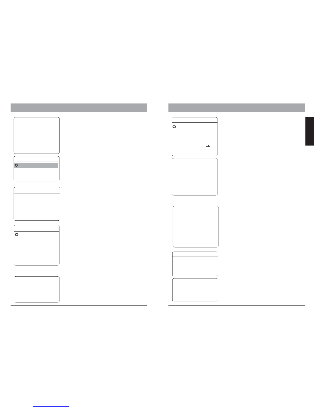
System Setting
In systemsetting menu, youcan modify operationand
display setting,such as domelabel, temperature and
display ofvarious value onthe operational screen.
EDIT DOME LABEL
LABEL
BACK
EXIT
:
ENTRANCE
INITIAL INFO
SPEED DOME V1.00
PROTOCOL:FACTORY
DOME ADDRESS:001
COMM:4800,N,8,1
BACK
EXIT
6.OSD - System Setting 6.OSD - Motion, Clear
Initial information:
Shows the information about current setting.
Dome Label:
1. use UP or DOWN to change the charactor.
2. use RIGHT to move to next char.
3. use RIGHT to move to last char and save.
4.useLefttofirstcharandcancel.
Display setup
Dome label:
Preset label:
Zoom label:
Zone label:
Direction label:
Temperature label:
Actuvate the display for the on-screen info in
operaton mode.
thenameofdome
shows the labe of every preset
shows zoom factor on screen
shows the zone name
shows the coordinates
shows the cur. temp in the speed dome
DISPLAY SETUP
DOME LABEL OFF
PRESET LABEL OFF
ZOOM LABEL ON
ZONE LABEL OFF
DIRECTION LABEL ON
LABEL OFF
BACK
EXIT
TEMPRATURE
Some productsmay not beavailable in yourcountry, pleasecontact our distributorfor more details Some productsmay not beavailable in yourcountry, pleasecontact our distributorfor more details
14
ENGLISH
SYSTEM SETTING
EDIT DOME LABEL
INITIAL INFO
DISPLAY SETUP
MOTION
CLEAR
PASSWORD SETUP
CLOCK SETTING
DOME ADDRESS
BACK
EXIT
MOTION
Motion control
AUTO FLIP
PROPORTIONAL PAN:
PARK TIME:
: Auto. Image flip in tilt range from 90° to
180°
depends onthe zoom factor,
the domewill adjust thepan and tiltspeed
automatically forcomfortable viewing.
defines theidle time priorto start a
custom definedaction( park action).Therange is
from 1to 240 minutes.This function can be
deactivated bysetting the minuteto 0.
PARKACTION:
POWER UPACTION:
EIS ENABLED:
PRESET FREEZE:
ADJ SPEED:
HEAD-DOWN:
the actionwhich will bestarted after
the idletime (park time).Selectable between Preset,
Scan, Pattern(Nr), Tour orNone.
defines theaction which will
be startedafter power upand self test.Selectable
between Auto,Preset 1, Scan, Pattern (Nr), Tour or
None. Byselecting Auto, the dome will resume the
last actionbefore power off.
Elctronic ImageStablizer.
adjust (20-100).
flip theimage.
Freezes imagewhen moving between
presets intour.
speed up
when thetemperature arrive thesetting
degree, theheater will beopen.
DEFOGGER:
AUTO FLIP ON
PROPORTION PAN ON
PARK TIME 005
PARK ACTION SCAN
POWER UP ACTION AUTO
FAN ENABLED 040
TEMP C/F CENT
ADVANCE SETTING
BACK
EXIT
Clear
You can clear setting’s memory or reset the camear to
factory default.The follwing functions are supported:
- Clear Zones
- Clear all presets
-Clearallpatterns
-Clearalltours
-Clearallwindows
- Factory defaults
Warning: The clear action can not be undone.
once a item is cleared it is impossible to
retrieve the deleted setting. Please make sure
that the requested clear action is desired.
CLEAR
CLEAR ALL ZONES
CLEAR ALL PRESETS
CLEAR ALL PATTERNS
CLEAR ALL TOURS
CLEAR ALL WINDOWS
FACTORY DEFAULTS
RESTART
BACK
EXIT
O
NEW PASSWORD : ******
ENABLE PASSWORD OFF
BACK
EXIT
LD PASSWORD : ******
CONF PASSWORD : ******
PASSWORD SETUP
Password setup
You can change password to access the OSD menu.
Default Password is 000000.
TIME 00:00:00
DATE 01/01/01
DAY MON
BACK
EXIT
CLOCK SETTING
Clock setting
Some function like Auto-Tracking require the timer for
activation.
Time: HH:MM:SS
DATE: YY/MM/DD
DAY: MON-SUN
ADVANCE SETTING
EIS ENABLED N/A
PRESET FREEZE OFF
DEFOGGER 015C
HEAD-DOWN OFF
ADJ SPEED 020
BACK
EXIT
DOME ADDRESS
S/N XXXXXXXXXXXX
CONF
DOME ADDRESS 0001
BACK
EXIT
XXXXXXXXXXXX
Dome Address
S/N:
CONF:
Dome Address:
*
the series number of dome( )
enter to unlock the configuration.
selectable between 0001-0255
before preset, you must set the address at 255.
Factory defaults
Page 10
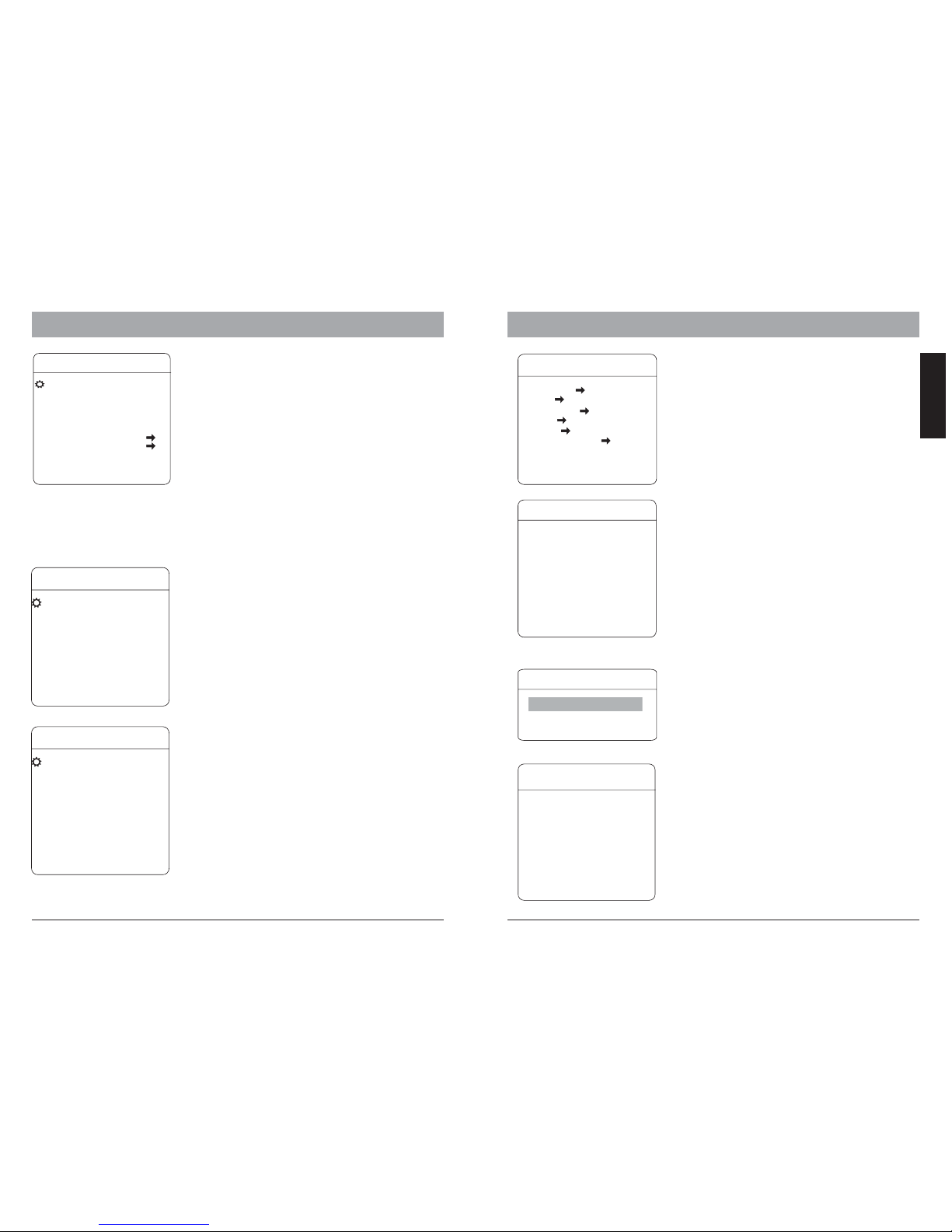
Camera setting
ZOOM SPEED:
DIGITAL ZOOM:
BLC MODE:
SLOW SHUTTER:
WDR:
In camerasetting menu, youcan setup cameramodule
related settings.please note thatdepends on module’s
capability, some function may not available. please contact
your localsales representative fordetailed information.
defines thespeed when performingzoom
function.
Activate ordeactivate the digitalzoom
function ofthe camera module.
Select theBack Light Compensationmode,
improves theimage when anobject has strongback light.
Activates theSlow Shutter functionof the
camera, whichprovides a higherlight sensibility inlowenvironment.
Activates theWide Dynamic Rangefunction, which
improves theimage contrast whenan object hasvery strong
light onbackground. Only availablewith camera modules
with WDR.
OSD - Camera Setting OSD - Preset, Scan
CAMERA SETTING
ZOOM SPEED HIGH
DIGITAL ZOOM ON
BLC MODE OFF
SLOW SHUTTER ON
LINE SYNC N/A
WDR MODE N/A
ADVANCE SETTING 1
ADVANCE SETTING 2
BACK
EXIT
ADVANCE SETTING 2
AE MODE AUTO
SHUTTER N/A
IRIS N/A
BRIGHT N/A
WB MODE AUTO
RGAIN N/A
BGAIN N/A
HI-RESOLUTION OFF
BACK
EXIT
Advanced setting 2
AE MODE:
WB MODE:
ALC, PLC:
Under the advanced setting, you can make
improvements to image quality due to different
environmental conditions.
Auto Exposure mode. Depends on the light
condition in the surveillance area, you can set the AE in
different modes and adjust the parameters, such as
shutter speed, iris factor and brightness for the best
image quality.
White balance mode, a image improvement
based on DSP processing. you can also adjust the RedGain or Blue-Gain to change the color tone.
Average and Peak Level Control,
additional setting to WB function. only avialble with
dedicated camera modules.
Function setting
In function setting menu, you can define and activate
different PTZ funcitons, such as preset points, auto
scan, tours and Pattern. Presets and tour functions
can also be set or activated directly from keyboard
device without OSD. Please refer to the keyboard’s
manual for operation details.
EDIT PRESET LABEL
LABEL
BACK
EXIT
:ROOM 1
PRESETS:
PRESET NUMBER:
SET PRESET:
SHOW PRESET:
CLEAR PRESET:
AUTO-TRACKING:
EDIT PRESET LABEL:
G35M Series supports up to 128
presets. The number can be selected from 0 to 128.
Defining the preset points directly in
OSD by entering this menu item and move the PTZ.
press IRIS-OPEN key on the keyboard to save. If the
preset is pointed within digital zoom, it will
automatically go back to max. optical zoom range in
order to provide the best image.
Moves to current preset point
Clear the current preset
Start Auto Tracking, if the preset
is called.
For the current preset, you
can define a name which will be shon on the
operation screen once the preset is called. please
choose the preset number at first. The avaialbe
characters are: 0-9, A-Z, <,>,. and space.
PRESETS
PRESET NUMBER 001
SET PRESET
SHOW PRESET
CLEAR PRESET
AUTO-TRACKING ON
EDIT PRESET LABEL
BACK
EXIT
SCAN
SCAN NUMBER:
SCAN SPEED:
SET LEFT LIMIT:
SET RIGHT LIMIT:
CLEAR SCAN:
RUN SCAN:
EDIT SCAN LABEL:
TheSCANfunctionmovesthePTZbetween2predefined points in constant speed.The
following parameters can be set:
cruising speed between the
points.
defines the left point.
defines the right point
Delete the scan setting
starting the scan function
set the name for the scan
G35M Series supports up to 4 scan.
SCAN
SCAN NUMBER 01
SCAN SPEED 63
SET LEFT LIMIT
SET RIGHT LIMIT
RUN SCAN
EDIT SCAN LABEL
BACK
EXIT
CLEAR SCAN
Some productsmay not beavailable in yourcountry, pleasecontact our distributorfor more details Some productsmay not beavailable in yourcountry, pleasecontact our distributorfor more details
15
ENGLISH
ADVANCE SETTING 1
IR CUTTERFILTER AUTO
IR CUTON TIME N/A
IR CUTOFF TIME N/A
THRESHOLD 10dB
MAX GAIN 28dB
EXPOSURE COMP OFF
MIRROR OFF
FLIP OFF
SHARPNESS 015
BACK
EXIT
Advanced setting1
IR CUTFILTER:
Max Gain:
EXPOSURE COMP:
MIRROR, FLIP:
SHARPNESS:
Enables theremoval of InfraredCutter
Filter (IRC),also known as“DAY/NIGHT” mode. with the
removal ofIRC, the cameraturns into Black/Whitemode and
has highersensibility to low-lightor IR-Light inthe night.
Selectable betweenOn, Off, Auto or Time. Only available
on cameramodule with IRCfunction.
improve theimage quality inthe Night modus
open/close theexposure compensation
function
mirror andflip image
Sharpness adjustion
FUNCTION SETTING
PRESETS
SCAN
PATTERNS
TOUR
ZONES
TIME RUNNING
BACK
EXIT
Page 11
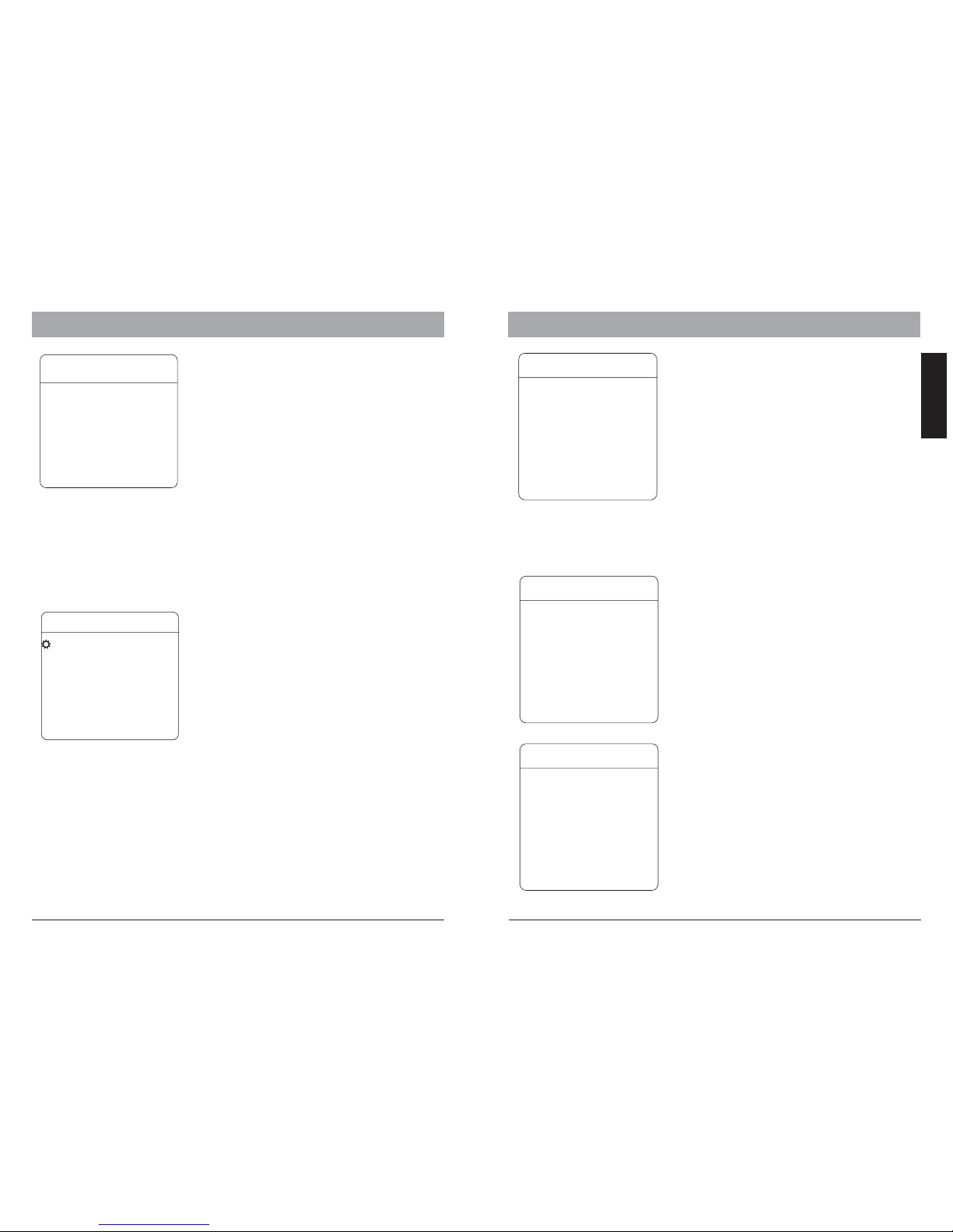
6.OSD - Patterns, Tours 6.OSD - Zones and Privacy Mask
PATTERNS
Pattern
Pattern records the user’s operation steps on
performing PTZ control and stores as a track. The
G35MSeriescanrecordupto4trackswithmax.
180 sec. each.
PATTERN NUMBER:
PROGRAM PATTERN:
RUN PATTERN:
CLEAR PATTERN:
EDIT PATTERN LABEL :
Selects the pattern number,
from1to4
Starts recording the pattern
when selected. you can perfome PTZ movement for
recording and shall not exceed 180 sec. Press IRISOPEN to save the track.
Starts the current pattern
Delete curretn pattern.
Sets the name for current
pattern.
PATTERN NUMBER 1
PROGRAM PATTERN
RUN PATTERN
CLEAR PATTERN
EDIT PATTERN LABEL
BACK
EXIT
Tour
Tour is an auto-run through selected preset
pointswithdefinablepausetime.Atourcan
store up to 32 presets points.
TOUR DWELL:
TOUR PRESETS:
RUN TOUR:
pause time for every stop on the
preset points. selectable between 000-255(s).
pressIRIS-OPENKeyonthe
keyboard device to enter the preset point
selection. Move the joystick with up and down to
select the preset points by number and save the
setting with IRIS-OPEN key. with IRIS-CLOSE
keyyoucanmovetothepreviousselection.Ifa
select point has the value 0, all the following
presets points will be ignored.
StartsthetourandexittheOSD
menu.
EDIT TOUR
TOUR DWELL 001
00-00-00-00-00-00-00-00
00-00-00-00-00-00-00-00
00-00-00-00-00-00-00-00
00-00-00-00-00-00-00-00
RUN TOUR
BACK
EXIT
Zone
upto8zones
You can define the zones in the whole PT range up
to withindividuallabel.Whenthe
display setting “Zone Label” is activated, the
label will be displayed on the operation screen.
Thedefinitionofthezonesshouldnotbe
overlapped.
ZONES NUMBER:
SET LEFT LIMIT:
SET RIGHT LIMIT:
CLEAR ZONE:
EDIT ZONE LABEL :
Current zone selection
Left limit of the current zone
Right limit of the current zone
Delet the current zone
change the laben of current
zone.
ZONES
ZONES NUMBER 1
SET LEFT LIMIT
SET RIGHT LIMIT
CLEAR ZONE
EDIT ZONE LABEL
BACK
EXIT
Some productsmay not beavailable in yourcountry, pleasecontact our distributorfor more details
Some productsmay not beavailable in yourcountry, pleasecontact our distributorfor more details
17
18
ENGLISH
TIME RUNNING
DAY SUN
TIME CHANNEL 1
STARTTIME 00:00
END TIME 00:00
RUNNING NONE
BACK
EXIT
Time Running
Youcansetupthetimertostartafunctionlike
preset,tourorpattern.Eachdaycanbeset4
action.
LANGUAGE
LANGUAGE ENGLISH
BACK
EXIT
Language:
Selectable betweenEnglish and French.
Page 12
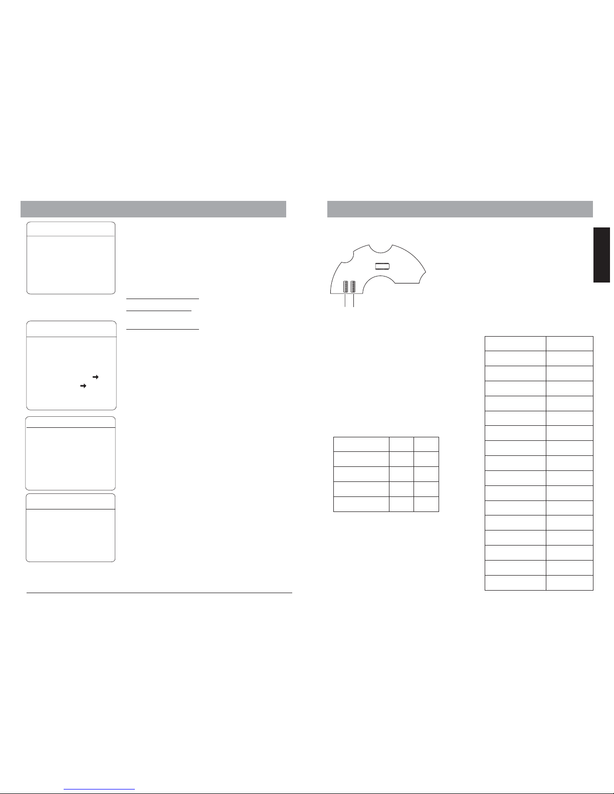
6.OSD - Alarm Setting
Alarms
RESUME: Continuethe function onthe camera ,if it
was settingbefore the alarms.
RESET DELAY: Howlong the camerastay in Alarm
position.
ALARM CONTACT: Setting between N/C (normal
Close) orN/O (normal Open).
ALARM NUMBER:curent Alarm number.
ALARM ACTION: Setting for PRESET, SCAN, TOUR,
PAT 1-4, or NONE, if the camere inAlarm position.
ACTIVATE AUX:
ALARM PRIORITY:
Setting Alarm Output, when Alarm is
activate. Selectbetween AUX1, AUX2 (not connected)
or BOTH.
define thepriority of thealarm input.
ARM SETTING:define the operationtimer of the alarm
ENGLISH
7. Dome Address & Protocol
Sw1 Sw2
Protocol setting
In order to establish a connection for
telemetric control with keyboard device. you
need to setup the dome address and protocol.
The G35M series are capable with multiple
communication protocol. The setting can be
changed through the DIP-Switches on the rear
side of the connector boards as Illustrated.
please use the following table for details setup.
current pattern.
Baud rate
DIP 7 DIP8
2400 bps 0 0
4800 bps 1 0
9600 bps 0 1
19200 bps 1 1
SW 1:
represent thedomes address inbinary form.
please referto the liston next pagefor reference.
SW 2:
Used for protocol settting and baud rate.
DIP1to6:Protocolsetting
DIP 7 and 8: Baud rate setting
Protocol / DIP 123456
VIDO B02 001100
DIAMOND 100100
HUNDA 101100
KALATEL 010100
LILIN 110100
MOLYNX 001000
PANASONIC 111000
PELCO (D/P) 100000
PHILIPS 000001
SAE 010000
SAMSUNG 000100
SANTACHI 011000
UNIVISION 010001
VCL 110000
VICON 101000
AD 100001
Some productsmay not beavailable in yourcountry, pleasecontact our distributorfor more details
ALARM SETTING
ALARM NUMBER 001
ACTION TOUR
ACTIVATE AUX AUX1
ALARM PRIORITY LOW
BACK
EXIT
ALARM
Note: VIDO B02 Protocol is fully
compatible with VIDO B01. For
previous version of Vido products
please set to B02
WINDOW BLANKING
WINDOW NUMBER 01
EDIT WINDOW
ENABLE WINDOW OFF
CLEAR WINDOW
BACK
EXIT
Privacy Mask ( Window Blanking)
Privacy Maskis used toprotect the privacyarea not tobe
displayed oncethe camera ispointed on, suchasu
levatory areaor the operationdesk of anATM machine. It
might berequired for videosurveillance application
depends onthe local lawregulation. The G35M supports
up to24 private masks.( depends oninstalled camera
module, pleasecontact your localsales representative
for moreinformation)
Hitachi camera modules
Sony Camera modules:
LG,CNB Camera modules:
: 8 masking area.
up to 24 masking area( except
the45seriesprovidesonly8)
no masking function.
WINDOW NUMBER:
EDIT WINDOW:
ENABLE WINDOW:
CLEAR WINDOW:
Mask number
Edit positionof the maskby joystick of
the keyboard.presse IRIS-OPEN tosave.
shows themask on screen OFF
Delete themask
ALARMS
Resume OFF
SEQUENCE 001
RESET DELEY 030
ALARM CONTACT N/O
ALARM SETTING
ARM SETTING
BACK
EXIT
ARM SETTING
DAY SUN
ARM STATE OFF
ARM TIME N/A
UNARM TIME N/A
BACK
EXIT
19
Page 13
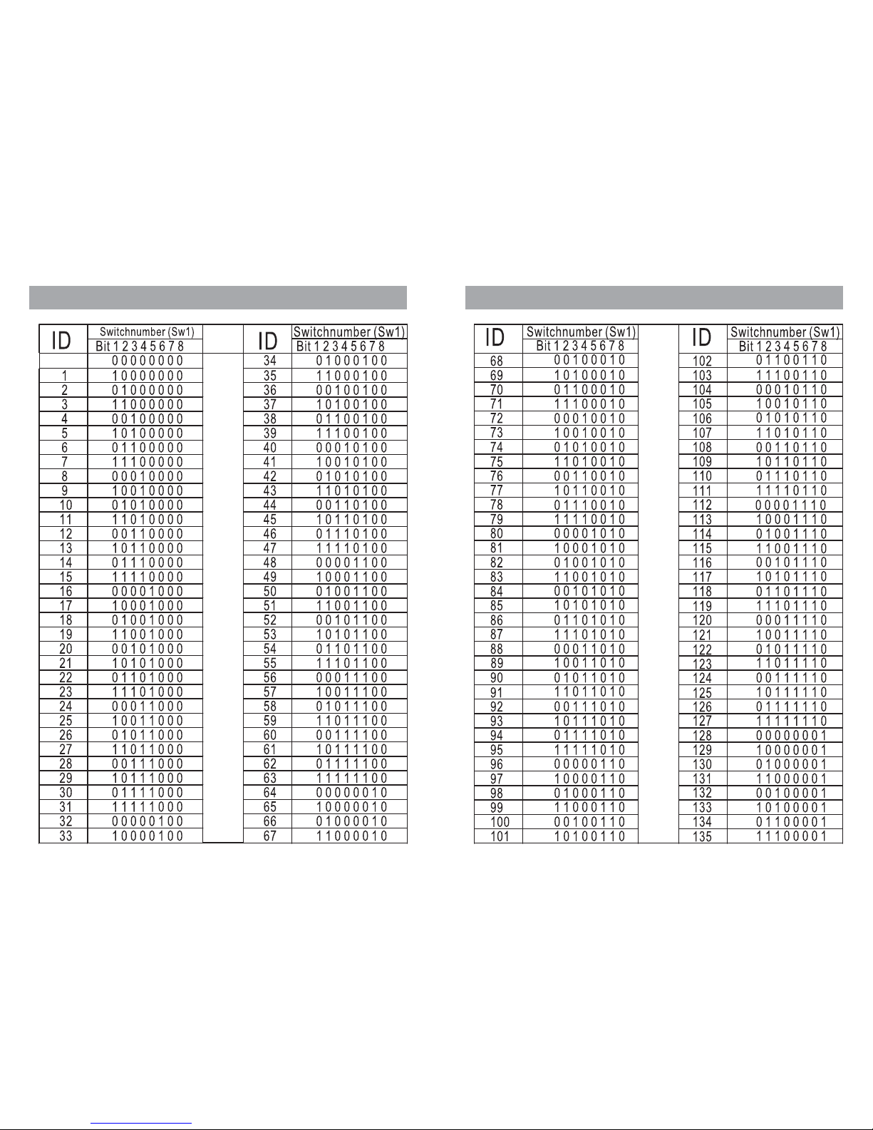
7. Address ID, 1 to 67
7.Address ID, 68 to 135
Page 14
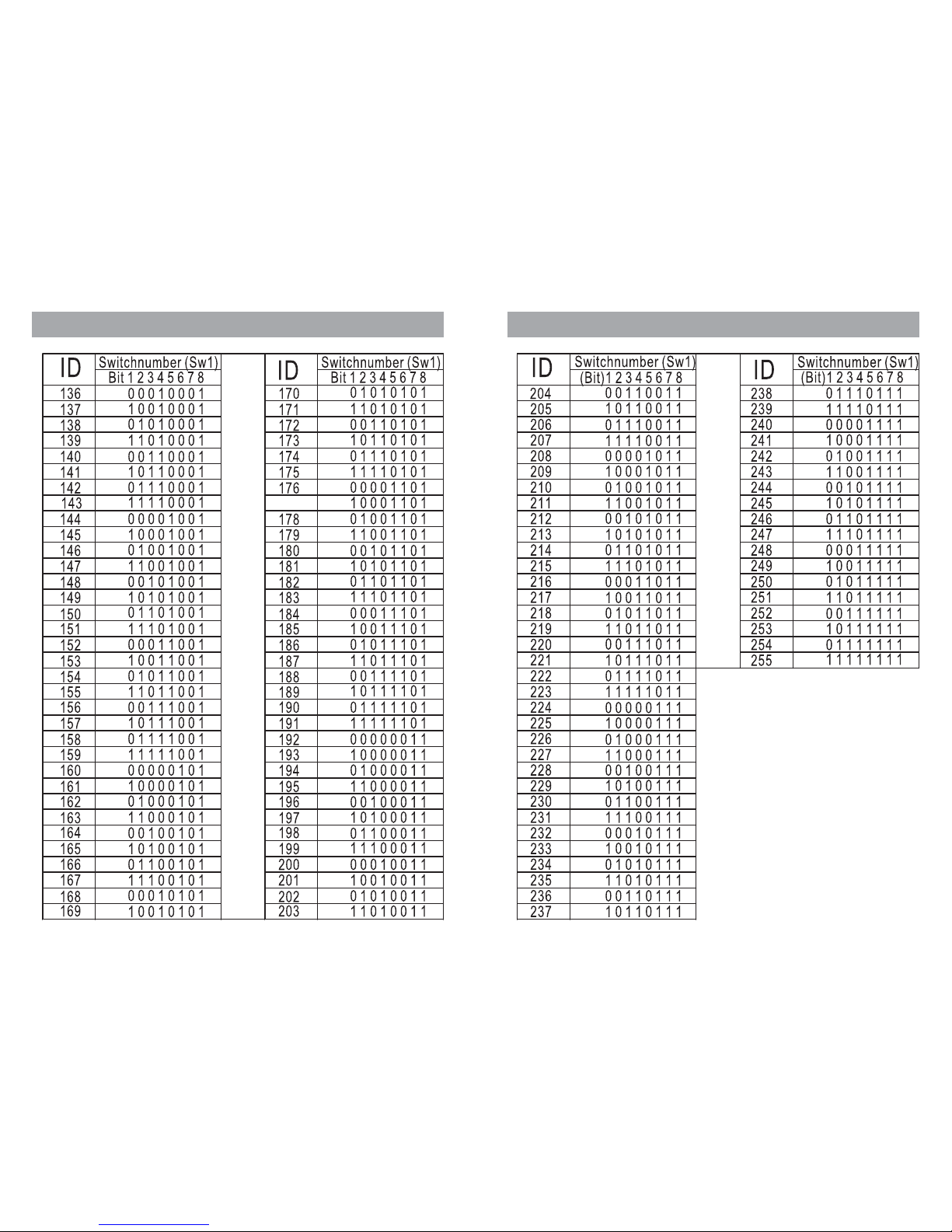
7. Address ID, 136 to 203
177
7. Address ID, 204 to 255
Set to 255, for software configuration.
Page 15
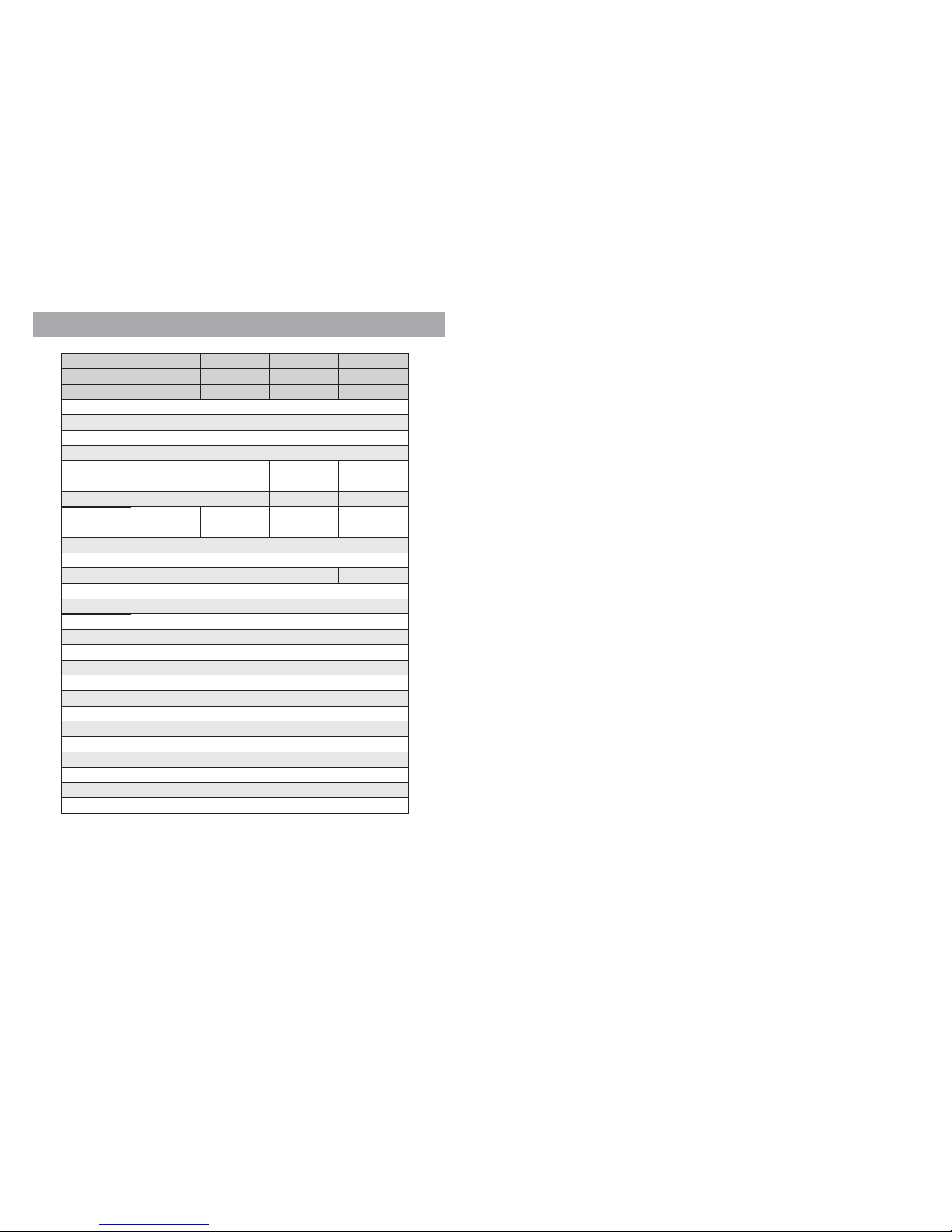
8. Specification
Some productsmay not beavailable in yourcountry, pleasecontact our distributorfor more details
25
Object Tracking
(only G65AT serie)
Communication
Preset Positions
Auto Pan
Tour / Sequence
Alarm inputs
Operating Temp.
Power
Manual activation / Preset triggering / Scheduled activation
Tracking zone selection
RS-485, , coax16 Multiple protocol supported
128 Presets
Yes, between 2 presets
4 progr. Tours with max 32 presets/ 4 Pattern up to 180s
7 inputs / 2 output
Indoor: -10 5℃to 0℃
12V DC / 20W
On-Screen Display
OSD Menu
Date/ Time/ Zoom Rate/ Temperature/ Zones/ Camera name
Setup/ Automation programming/ Password protection
Iris Control
Gain Control
Video Output
S/N Ratio
PTZ Characteristics
Auto / Manua/ Auto Slow Shutter
Auto / Manual (-3 to 28 dB, 2 dB steps, 16steps)
VBS: 1.0Vp-p (Sync Negative), Y / C Output
Shutter Speed
1 to 1/10,000 Sec. 1/3 to 1/10,000 Sec.
Focus
White Balance
Auto / Manual
Auto / Manual (ATW, Indoor, Outdoor, One Push WB, Manual WB)
Wide Dynamic Function (SB18WD/ SB26WD / SB36WD models)
Night: 0.01Lx (1/3)
Viewing Angle
Image Sensor
1/4 inch Ex-View CCD
Model
AU-G35M-SC18
AU-G -SB1835M AU-G -SB2635M AU-G -SB3635M
Day / Night Day / NightDay / Night
Signal Format
Scanning
PAL/NTSC
Progressive
H. Resolution
470 TVL, 440K Pixels (PAL)/ 540 TVL (High Resolution)
48.0° (Wide end) 54.2°(Wide end)
2.2° (Tele end)
57.8° (Wide end)
1.7° (Tele end)2.8° (Tele end)
Zoom
Min. Illumination
18× Opt. / 12× Digital 26× Opt. / 12× Digital
36× Opt. / 12× Digital
0.7 Lux (1/50 sec., Color) Day: 0.7Lx (1/50), 0.1Lx (1/3)
Day: 1.4Lx (1/50), 0.1Lx (1/3)
Night: 0.01Lx (1/3)
-
More than 50 dB
AU-G -SB18WD
with WDR
35M
AU-G65-SB26
AU-G -SB26WD
with WDR
35M
AU-G -SB36WD
with WDR
35M
Night: 0.01Lux
Day: 1.0 Lux (50IRE, F1.6)
360° PAN (0.4° ~80° per sec) / 120° Tilt (0.4°~60° per sec)with
Auto-Flip/ Vario-Speed control* / Proportional & constant PT speed
Operating Environment
-40℃ to 60℃ / humidity up to 95%
Page 16
© 2009VIDO Electronics vertriebsG.m.b.H.
Vienna, Austria. All rightsreserved.
www.vido-europe.com
 Loading...