

Vido AU-DVRS-4A User Manual
4 CH Digital Video Recorder
User’s Manual
AU DVRS 4A V1.0
Please read this instructions thoroughly before operation and keep the manual in a safe
place for further reference.
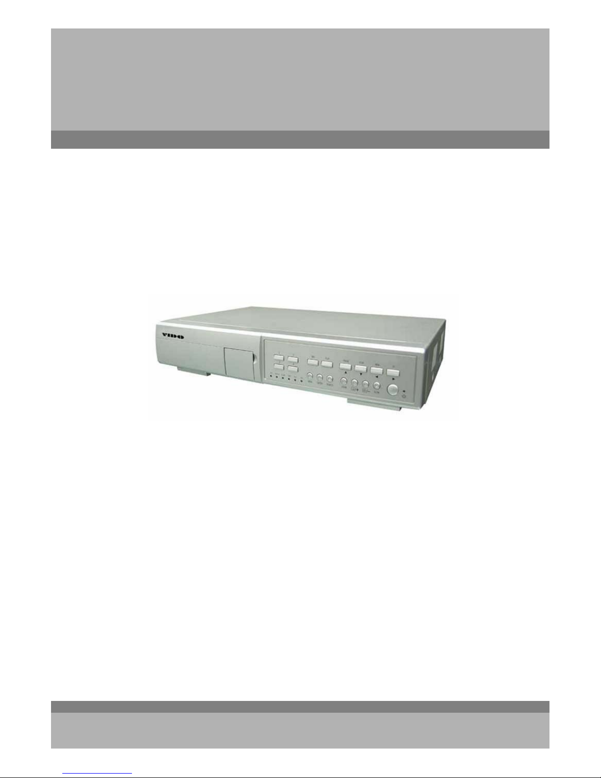
AU-DVRS-4A
4 Ch. DVR Stand Alone
All the safety and operating instructions should be read before operation. The improper operation may cause
permanent damage.
‧ This adaptor is only for this machine. Do not use it for other electronic products or it will damage other products.
‧ Please lift and place this equipment gently.
‧ Do not expose this equipment to direct sunlight.
‧ Do not use this equipment near water or in contact with water.
‧ Do not spill liquid of any kind on the equipment.
‧ Please power down the unit before unplugging.
‧ Do not block the ventilation holes at the top and bottom of the unit.
‧ Do not switch the Power On & Off within short period of time (within 3 seconds).
‧ Do not attempt to service this equipment by yourself.
‧ Installation should be made by qualified service personnel.
‧
Do not try to retrieve the HDD data by PC.
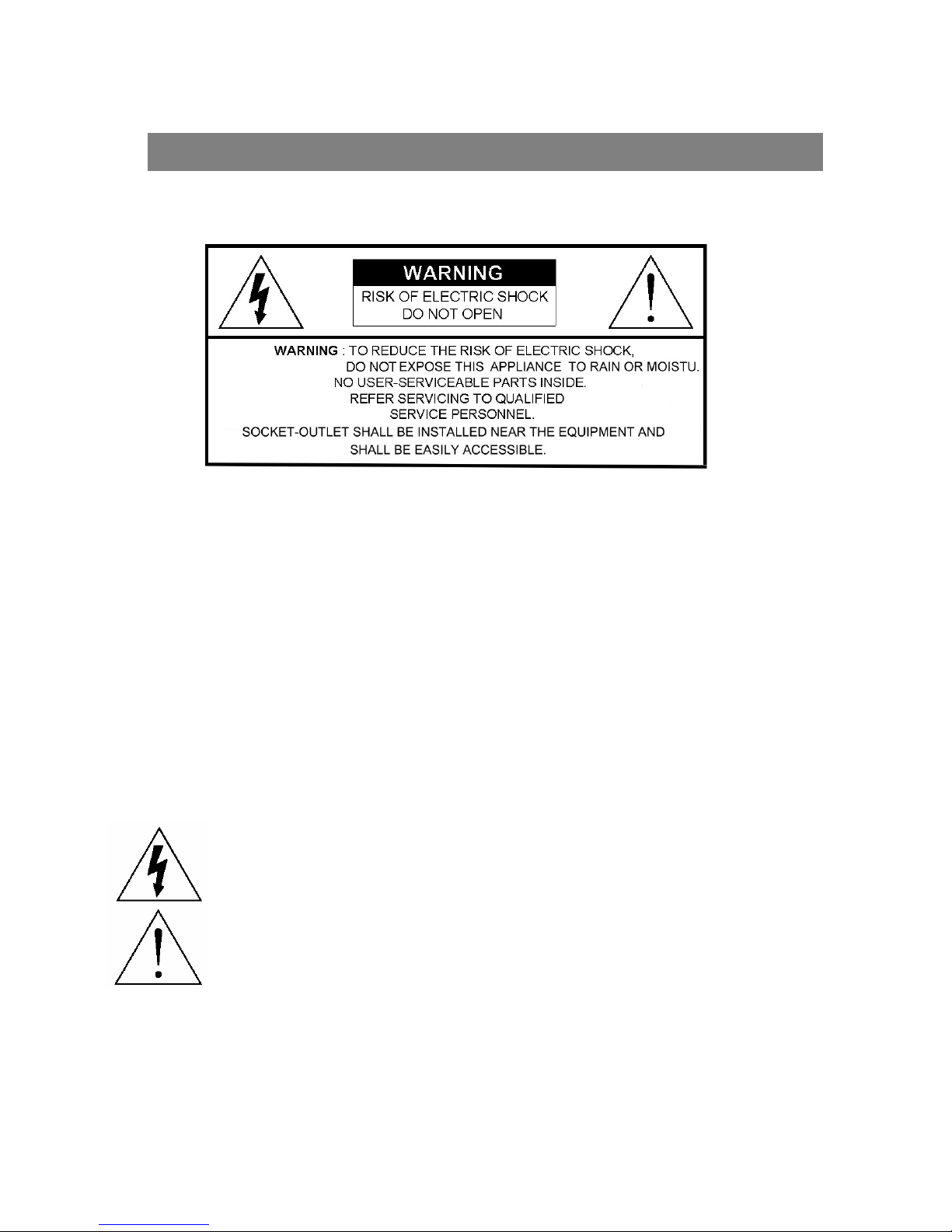
The lightning flash with arrowhead symbol, within an equilateral triangle, is intended to alert
the user to the presence of uninsulated "dangerous voltage" within the product's enclosure that
may be of sufficient magnitude to constitute a risk of electric shock to persons.
The exclamation point within an equilateral triangle is intended to alert the user to the presence
of important operating and maintenance-(servicing) instructions in the literature accompanying
the appliance.
WARNING
1

What do you get
What do you get??
‧ FEATURES -------------------------------------------------- --------------------------------------
‧ PACKAGE CONTENT --------------------------------------------------------------------------
Before Operation
Before Operation
‧ INSTALLATION GUIDE ------------------------------------------------------------------------
‧ FRONT PANEL -----------------------------------------------------------------------------------
‧ REAR PANEL -------------------------------------------------------------------------------------
Basic Operation
Basic Operation
‧ GETTING STARTED------------------------------------------------------------------------------
‧ OPERATION----------------------------------------------------------------------------------------
Detailed Menu Setup
Detailed Menu Setup
‧ MAIN MENU ---------------------------------------------------------------------------------------
‧ MENU OPTIONS ------------------------------------------------------------- --------------------
Advanced Operation
Advanced Operation
‧ OPERATION OPTIONS ------------------------------------------------------------------------
‧ KEY LOCK ----------------------------------------------------------------------------------------
‧ RS-232 PROTOCOL ----------------------------------------------------------------------------
‧ TROUBLE SHOOTING---------------------------------------------------------------------------
‧ SPECIFICATIONS---------------------------------------------------------------------------------
APPENDIX #1 – INSTALL THE HDD ----------------------------------------------------------
APPENDIX #2 – REPLACE THE HDD --------------------------------------------------------
APPENDIX #3 – PIN CONFIGURATIONS ---------------------------------------------------
APPENDIX #4 – RECORDING SPEED----------------------------------------------------------
APPENDIX #5 – NETWORK APPLICATION--------------------------------------------------
TABLE OF CONTENTS
3
3
4
5
7
8
8
10
10
18
19
19
19
20
21
22
23
25
26
2
FEATURES
DVR Features
• Wavelet compression format replaces Time-Lapse VCR + Multiplexer / Quad
• 4 audio inputs / 2 audio outputs
• On Screen Display and Remote Control via Video Server & PC
• Picture-in-picture (PIP) and Picture-on-Picture (POP) function in live
• Motion detection & motion trigger recording function
• Alarm input & output function
• Video loss detected on each channel
• Linear Zoom (2x~4x)
• Multiplexer & Quad recording mode switching
• Recording rate up to full size 30 fields/sec. or Quad size 240 fields/sec.
• Support 1 removable HDD with hot-swap capability, IDE TYPE (over 250 GB)
• Multiple quick search by date/time, alarm, full, motion list
• Security password protection
• RS-232, RS-485 communication protocol
What do you
get ?
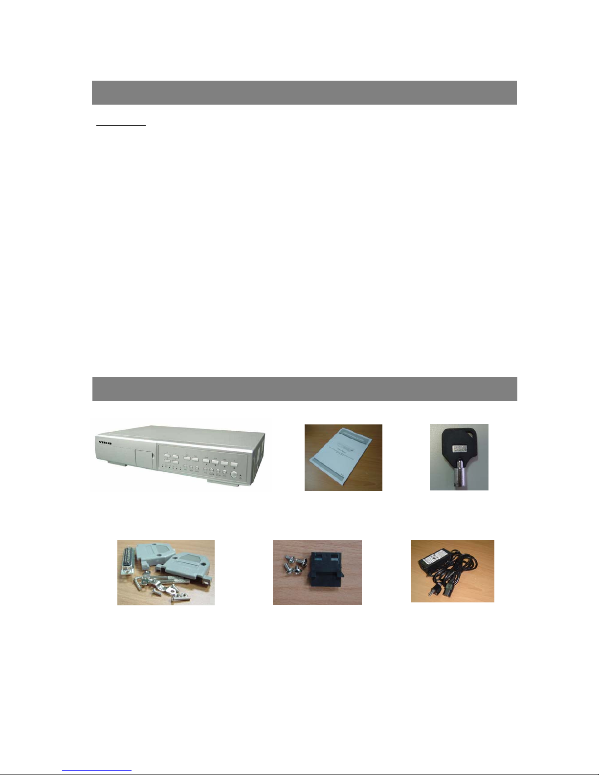
PACKAGE CONTENT
3
Warning:
1. Please check the package to make sure that you receive the complete accessor ies which includes the
components shown above.
2. This adaptor is suited for DC19V 2A use. If it is damaged, user can find replacement adaptor easily in the locality with this specification.
Accessories pack
Power Adapter and Cord
Accessories pack
2 Keys
User ManualDigital Video Recorder(with HDD cartridge)
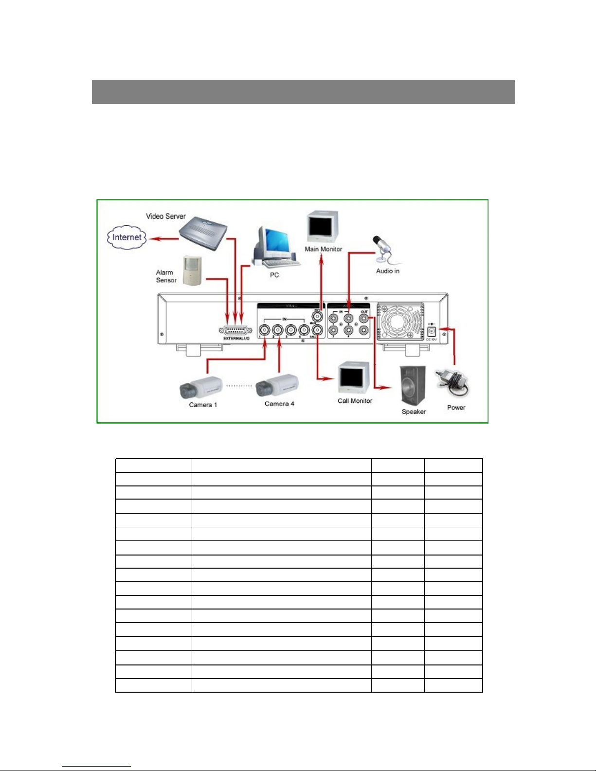
1. Connect cameras and monitor to the DVR.
2. Shown below is an example of connecting the DVR to your existing Observation System.
3. Install HDD (The compatible HDD brands are listed in the following table.)
Please refer to page.21 Appendix #1 for installation instructions.
Note: The HDD must be installed before turning on the DVR. If HDD is not installed, the DVR would function as a 4 CH multiplexer.
INSTALLATION GUIDE
Before Operation
Manufacturer Model Capacity Rotation
HITACHI Deskstar 180 GXP (120 GB) 120GB 7200 rpm
HITACHI Deskstar 7K250, HDS722516VLAT20
160GB
7200rpm
HITACHI Deskstar 7K250, HDS722525VLAT80 250GB 7200rpm
HITACHI Deskstar 120GXP (80GB) 80GB 7200 rpm
HITACHI Deskstar 120GXP (120GB) 120GB 7200 rpm
M ax tor DiamondMa x 53 6DX (60G B) 4W060H4 6 0GB 5400rpm
M ax tor DiamondMa x Plus 9 80GB 7200 rpm
M ax tor DiamondMa x Plus 9, Mod el#6Y120L 120GB 7200 rpm
M ax tor DiamondMa x Plus 9, Mod el#6Y160L0 160GB 7200rpm
Maxtor
MaxLine Plus Ⅱ, Mode l#7Y250P0
250GB 7200rpm
Seagate Barracuda ATA IV, ST380021A 80GB 7200rpm
Seagate Barracuda ATA V, ST3120023A 120GB 7200 rpm
Seagate Barracuda 7200.7 Plus, ST3160023A 160GB 7200 rpm
Western Digital Caviar WD1200BB-00CAA1 120GB 7200rpm
Western Digital Caviar WD2000BB-00DWA0 200GB 7200rpm
Western Digital CaviarSE WD2500JB 250GB 7200rpm
COMPATIBLE HARD DISK MODELS
4
NOTE: For non-stop long-time recording, we suggest to have tw o HDD for recording to ensure good reliability of HDD.
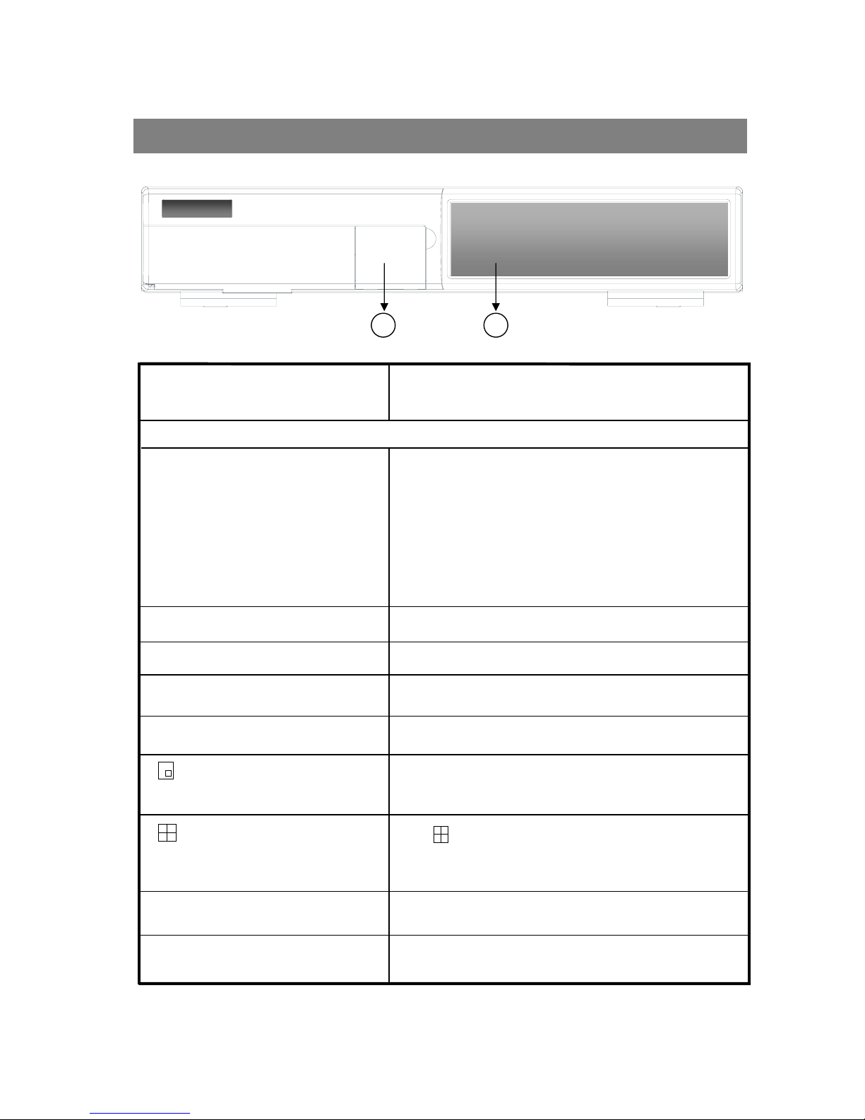
FRONT PANEL
5
12
/ - 4 CHANNELS DISPLAY MODE
/ + PICTURE IN PICTURE
Press Power to turn ON / OFF the DVR.
POWER
SLOW
Press “ ” button for 4 CH display modes and press twice to enter
POP (Picture On Picture) function.
Press “ - ” button can change the setting in the menu.
PIP: Press “PIP” button for Picture in Picture screen.
+ : Press “+ ” button can change the setting in the menu.
Press ZOOM button to enlarge the picture display.
ZOOM
Press SEARCH button for searching recorded video.
SEARCH
Press ENTER button for confirmation.
ENTER
Press MENU button to enter main menu.
MENU
The LED Light is ON under following condition.
‧HDD : HDD is reading or recording.
‧HDD Full : HDD is full
‧ALARM : To turn off the ALARM LED light, please refer to page.13
and set the ALARM mode as OFF.
‧TIMER : When Timer is Enabled
‧PLAY : Playing mode
‧REC : Recording mode
2. CONTROL PANEL
LED LIGHT
To slow down the speed of playing mode.
1. REMOVABLE HDD CARTRIDGE & KEYHOLE
Please refer to page.22 Appendix #2.

6
‧FF : Play video fast forward. (Press FF button again to adjust speed
from 1, 2, 4, 8, 16, 32 times)
‧ ► : Under setup mode, it works as Right button.
FF / ►
REW / ◄
‧REW : Play video fast backward. (Press REW button again to adjust
speed as 1, 2, 4, 8, 16, 32 times)
‧ ◄ : Under setup mode, it works as Left button.
STOP / ▼
‧STOP : Under DVR Recording / Playing mode, it can stop the action.
‧ ▼ : Under setup mode, it works as Down button.
PAUSE / ▲
‧Pause : Under DVR playing mode, it can pause the action.
‧ ▲ : Under setup mode, it works as Up button.
PLAY Press “PLAY” button toplayback recorded video.
REC
Press “REC” to start recording.
CAMERA SELECT (1-4) Press the Camera Select (1-4) to select the camera.

7
1. EXTERNAL I/O
‧Controlled remotely by an external device or control system suchas Video Web Server or PC.
‧Alarm input, external I / O expansion.
2. VIDEO INPUT (1-4)
Connect to video source, such as camera.
3. CALL
Connect to CALL monitor. Show the Switch Display.
When alarm trigger happens, the call monitor will show the triggered channel for a period of time.
4. MAIN
Connect to Main monitor.
5. AUDIO IN (1-4)
Connect to audio sources, such as a microphone.
‧IPS should be set to 30 (for NTSC) or 25 (for PAL)
* 4 audio inputs, but can only record one input at the same time.
6. AUDIO OUT
Connect to monitor or speaker.
‧IPS should be set to 30 (for NTSC) or 25 (for PAL)
*
with 2 mono audio outputs from the same source.
7. FAN
For ventilation, do not block the opening.
8. POWER
Please use the provided power cord.
Warning:
1. This adaptor is only for this machine. Do not use it for other electronic product or it will damage other products.
2. This adaptor is suited for DC19V 2A use If it is damaged, user can find replacement adaptor easily in the locality with this
specification.
REAR PANEL
EXTERNAL I/O
1 2
CALL
3 4
2 4
MAIN
OUT
IN
1 3
IN
DC 19V
OUT
1
2
3
4
5
6
7
8
RECORDING
The DVR offers 4 recording modes, variety of recording modes. Refer P.25 for advanced setting of recording speed and
resolution. Under the recording status, if power is off accidentally, recorded video will still be stored in the HDD. DVR will
return to original recording setting after power restores again.
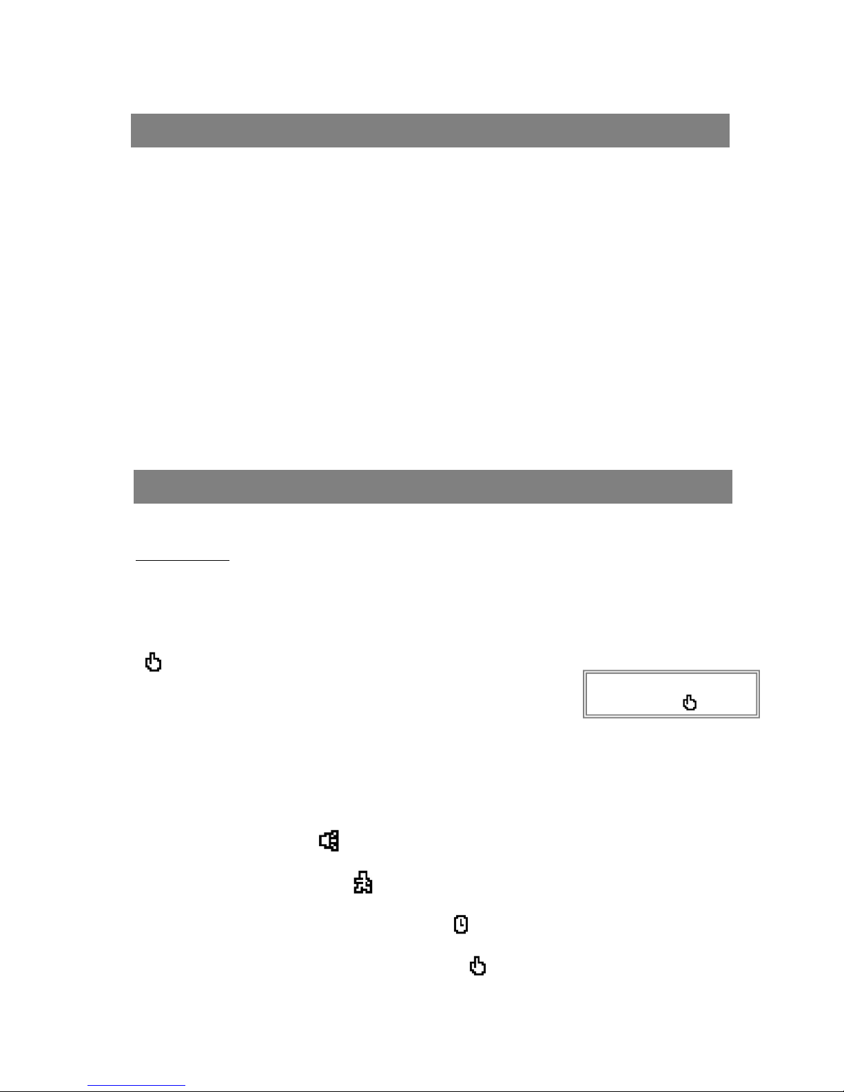
On the screen, you will find the date, time, HDD recording type, the available space of HDD (in GB) left and the symbol
“ ”represents the recording mode.
NOTE : 1. Under O/W Recording mode, previously recorded files will be
automatically ov erwr itten wit h out further warnin g not i c e s, when the
HDD is full.
2. If the HDD capacity is only 5 GB left, it will display “5 GB” on the up-right
screen and shows orange color, and it will buzz for seconds; so as in 4GB, 3GB, 2GB and 1GB. If the
O/W Recording mode (NOTE 1) is on, it won’t have the warning buzzer.
There are 4 recording modes: Alarm, Motion, Timer and Manual Recording.
1. ALARM RECORDING
DVR is triggered by an alarm input. symbol will be shown on the triggered channel. (refer to page13)
2. MOTION TRIGGER RECORDING
Recording is triggered by motion detection. symbol will be shown on the triggered channel. (refer to page14)
3. TIMER RECORDING
Recording is scheduled by a Timer. It will indicate by the symbol . (refer to page11)
4. MANUAL RECORDING
Recording is initiated manually by pressing the REC button. Symbol will be shown.
Connect the AC power cord and plug into an electrical outlet. The Red LED indicator light will be ON and the DVR is
in Standby mode.
1.
Press the Power button. The POWER LED will turn from red to orange, and other red LED indicators will turn ON. It
takes approximately 5 to 15 seconds to boot the system with the message : “ HDD Detecting ”. Once connected, the
POWER LED will change to green color, and the Alarm LED will be ON.
2.
Before using the DVR, please have a HDD installed ready, or it will function as 4 CH multiplexer (refer to Appendix #1 and
Appendix #2 for installation or removal of a HDD).
GETTING STARTED
Basic Operation
OPERATION
2002 – JAN –01 01:02:03
●OW
3.
Before operating the DVR, sets the system time first. (refer to page.11).
NOTE : 1.If the HDD is not installed correctly or not installed, the “HDD not found” message will
appear for 3 seconds and then return to 4 CH Multiplexer display mode.
2.To switch the system, you need to turn off the power and pull out the AC power cord, before you reconnect
the power, press “POWER” + “FF” to NTSC system or “POWER” + “REW” to PAL system and then
reconnect the AC power cord, the DVR will be auto-detecting.
8
(OW : HDD Overwrite)
 Loading...