

Vido AU-DVRS-04LH User Manual

AU-DVRS-04LH User's Manual
DIGITAL VIDEO RECORDER


Installation and Precaution
1. Warning
This unit is designed, to be used in indoor condition, to reduce fire and shock hazard, do not expose
the unit to rain or moisture.
Prevent any foreign object or liquid to enter the unit. In case, there is any foreign object or liquid go
inside the unit, cut off the power immediately, and call for a qualified service person to inspect and
test the unit, before putting the unit back to operation.
Do not touch any part of the unit with wet hands.
Do not block any part of ventilation grill / holes of this unit. Do not place other equipment on the
top of this unit.
Place the unit away from direct sunlight, hot source, and radiator.
Install the unit horizontally, and in well ventilation place, to prevent the unit to become overheated.
Do not operate the unit under power supply other than nominal voltage.
2. Precaution
No user serviceable components inside this unit. Refer servicing to qualified service personnel.
In case of malfunction, contact our local agent or regional representative for repairing.
This unit is delivered without the hard disk by default. Please contact our local agent or
regional representative, so they can install hard disk to suit for your storage and video image
retention requirement.
This unit supports all commercially available IDE hard disk.
In order to ensure stable operation of this unit, IDE hard disk from reputable factory should be
used.
This unit operates under 100-240 VAC, do not operate this unit outside this voltage range.
Once after the unit is connected to power supply source, some part of this unit is already
carrying high voltage, even without turning on the unit by pressing the “Power” button on
remote control and front panel. It is strongly recommended to completely unplug the unit from
power supply source, before opening up the unit for any kind of servicing.
1

Delivery Packing Checklist
This unit is packed with the following accessories, please kindly check immediately after unpacking the
box :
1、 1 no. of power supply cord
2、 1 no. of operating manual
3、 1 no. of Infra-red remote controller
4、 1 set of installation accessories
2

Index
FRONT PANEL………………………………………………...6
REAR PANNEL……………………………………………….. 8
HARD DISK INSTALLATION..................................................9
VOLTAGE OUTPUT & SENSOR INPUT AND ALARM
OUTPUT CONNECTION……………………………………..10
POWER ON AND OFF………………………………………...11
1.POWER ON……………………………………………………………………………. .11
2.POWER OFF…………………………………………………………………………… .11
SYSTEM SETUP………………………………………………12
1、TO ENTER MENU .......................................................................................................... 12
2、
MENU AND SCREEN PROMPT OPERATION ................................................................... 12
3、
SETUP MENU ............................................................................................................... 12
E
NTER SYSTEM PASSWORD................................................ 12
1、System Setting....................................................... 13
1.1System Password Setting .............................................. 13
1.2Language Setting..................................................... 14
1.3Time and Date Setting ................................................ 14
1.4Date Mode ......................................................... 14
1.5Time Indication Position Setting ....................................... 15
1.6Default Value Setting................................................. 15
1.7SW Update…………………………………………………………………………….15
RECORDING SETTING ............................ 16
1、TO ENTER THE MENU ................................................ 16
2、M
ENU AND SCREEN PROMPT OPERATION ................................. 16
3、S
ETUP MENU....................................................... 16
1、Record setting ....................................................... 16
1.1Schedule Recording ................................................. 17
1.1-1One Time ........................................................ 17
1.1-2Daily ........................................................... 17
3

1.1-3Weekly .......................................................... 17
1.2Event Recording .................................................... 18
1.2-1Motion Detection .................................................. 18
1.2-2 Sensor Detection .................................................. 19
1.3Repeat Recording.................................................... 20
1.4Recording Speed (Frame Rate) ........................................ 20
1.5 Compression Rate (Recording Quality) .................................. 20
1.6File Deletion ....................................................... 21
1.7File Lock / Unlock................................................... 21
HARDWARE SETTING ............................ 23
1.TO ENTER THE MENU ................................................... 23
2.MENU AND SCREEN PROMPT OPERATION .................................... 23
3.S
ETUP MENU ......................................................... 23
1、Hardware Setting .................................................. 23
1.1PTZ Camera Setting ................................................. 24
1.2PTZ Camera ID ..................................................... 24
1.3Sensor / Alarm Setting ................................................ 24
1.3-1Sensor Type ...................................................... 25
1.3-2Alarm Management Setting ........................................... 25
1.3-3Alarm output Setting ................................................ 25
1.3-4Alarm out Period ................................................... 26
1.3-5Manual de-activation of alarm output(Alarm Manual off).................... 26
1.4Network Setting...................................................... 26
1.4-1Static internet protocol............................................... 26
1.4-2Dynamic internet protocol ........................................... 27
1.4-3Network Password .................................................. 27
1.5Storage Setting....................................................... 28
RECORDING SEARCH / OPERATION ............... 29
1.Time Search ...................................................... 29
2.Event Search ....................................................... 29
3.List Search ........................................................ 30
4.Recording Operation................................................. 30
5.Playback operation .................................................. 31
OTHER OPERATION .............................. 32
1.Pan Tilt Control..................................................... 32
2.Zoom / Focus Control................................................ 32
3.Audio Item ........................................................ 33
4.Backup ........................................................... 34
4-1、IEEE 1394 Backup ..................................................................................... 34
4

4-2、USB Backup............................................................... ............................... 34
5.Status Indication .................................................... 35
6.SPOT Display ...................................................... 35
7.Hard disk format .................................................... 35
NETWORK SOFTWARE OPERATION ................ 37
1、GRAPHIC USER INTERFACE INTRODUCTION ................................. 37
2、CONNECT AND DISCONNECT............................................. 37
2-1、Signing On ................................................................................................... 37
2-2、Disconnect.................................................................................................... 38
3、L
IVE DISPLAY ........................................................ 38
4、PTZ C
AMERA CONTROL ............................................... 38
5、BACKUP FILE ........................................................ 39
6、O
PEN FILE .......................................................... 40
7、S
CREEN EXPAND ..................................................... 40
8、F
RAME RAT E SETTING ................................................ 41
Specification ............................................................. 42
5

Front Panel
1.Power Button
Turn the unit on or off.
2.Digits Buttons
Change time, password, and input IP address
3.Menu Button
Go to the top level of the menu tree
4.Setup Button
Other operation Menu
5.Channel Select Button
Select the channel. Toggle the screen between QUAD, 1,2,3 or 4
6.SPOT Button
Put the display mode to Spot Mode. Toggle the screen between Quad, Channel 1.2.3 or 4, under Spot
viewing
7.STATUS Button
System status indication
8.Power LED
Power on/off indication
9.HDD LED
HDD operation indication
10.REC LED
REC operation indication
11.Play LED
playback operation indication
12.REC Button
Toggle of recording on and off
13Rewind Button
Active only under playback operation, Toggle between 2X,4X,8X or 16X reverse Play
14.Playback Button
Active only under playback operation. Return the playback to 1X forward playback.
15.Fast Forward Button
Active only under playback operation. Toggle between 2X,4X,8X or 16X forward play
16.Pause/Frame Advance Button
Active only under playback operation. Pause the screen on playback
17.STOP/EXIT Buttons
Active only under playback operation. Stop playback process/Cancel of data input or leave the current
menu tree
6

18.Enter Button
Confirm of the data input
19.Up Button
Up action for menu tree navigation, pan/tilt etc..
20.Left Button
Left action for menu tree navigation, pan/tilt control etc..
21.Right Button
Right action for menu tree navigation, pan/tilt control etc..
22.Down Button
Down action for menu tree navigation, pan/tilt control etc..
23.Search Button
Go to "Search" item under the menu tree. Let user to search for video clip to playback
7
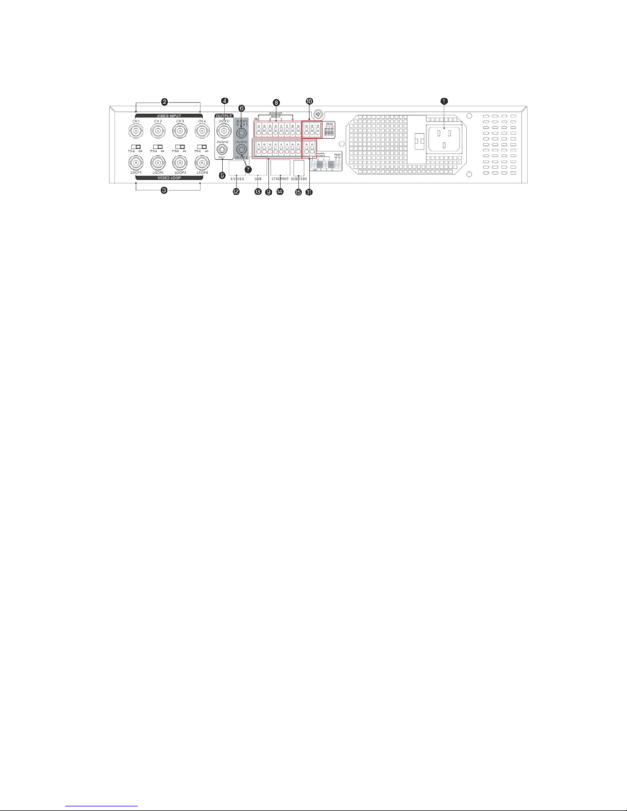
Rear Panel
1. Power Input
2. Camera Input 1~4
3. Loop Out 1~4
4. Video Output
5. Audio Output
6. Audio Input 1
7. Audio Input 2
8. Sensor Input 1~4
9. Alarm Output 1~4
10. RS232 Port
11. RS485 Port
12. S-Video Output
13. USB Port
14. LAN Port
15. IEEE 1394 Port
8

Hard disk installation
This unit is delivered without the hard disk by default. Please contact our local agent or regional
representative, so they provide qualified service personnel to install hard disk to suit for your storage
and video image retention requirement. The unit is not operational before installation of hard disk. The
maximum number of IDE hard disks, which can be installed in this unit is four. The size and number of
hard disks to be installed is to be determined by the video image quality and the online video retention
period requirement, please kindly refer to the storage calculation table below to determine the total size
of hard disks to be installed.
************Storage Table(720X480)
Standard High 1 High 2
Frame Rate
(Frame/Sec)
240GB 480GB 240GB 480GB 240GB 480GB
25 220hr 440hr 117.9hr 235.8hr 78.5hr 157hr
12.5 440hr 880hr 235.8hr 471.6hr 157hr 314hr
8.3 660hr 1,320hr 353.7hr 707.4hr 235.5hr 471hr
5 1,100hr 5,500hr 589.5hr 1,179hr 392.5hr 785hr
2.5 2,200hr 6,600hr 1,179hr 2,358hr 785hr 1,570hr
1 5,500hr 11,000hr 2,948hr 5,895hr 1,963hr 3,926hr
Installation Procedure :
1、 Unplug the unit from any power source. Once after the unit is connected to power supply
source, some part of this unit is already carrying high voltage, even without turning on the unit by
pressing the “Power” button on remote control and front panel. It is strongly recommended to
completely unplug the unit from power supply source, before opening up the unit for any kind of
servicing.
2、 Open the top of the unit case by undoing the screws. Identify the two hard disk holder (as
indicated in the figure above). Each hard disk holder can hold two IDE Hard Disks.
3、 Install the hard disk(s) on the hard disk rack, and use the screws (provided with this unit as
installation accessories) to fix the hard disk onto the rack securely.
4、Connect the IDE hard disk(s) onto the ribbon cable. If one IDE bus contain more than one hard
disk, then one should be set up as Master and the other as Slave, by setting the jumper on hard disks
respectively (please refer to the installation instruction of the IDE hard disk).
5、Connect the IDE ribbon cable to one of the IDE slot on the main board on the other end.
6、Connect the internal DC supply cable onto each hard disk.
7、Make sure there is no strained ribbon cable and DC supply cable inside, and then close the
casing top. Fasten the casing screws.。
8、Format the IDE hard disk according to the procedure as stated under “Hard Disk formatting”
section of this manual.
9

Voltage Output & Sensor Input and Alarm
Output Connection
Sensor Input
This unit has 4 numbers of isolated Sensor input to take voltage free relay outputs from peripheral alarm
sensors.
These Sensor inputs are protected from high voltage input from outside, by providing the opt-isolated
design
Sensor Input Setup :
Set the sensor type to “no(normal open)” or “nc(normal close)”.
This unit need to input external power supply to connect each sensor.
Alarm Output
Four alarm outputs are built into the system,
This unit need to input external power supply to connect each alarm.
10

Power ON and OFF
1、Power On
Before the first time of turning on the unit for operation, please make sure all points listed in the
“Installation and Precaution” section has been studied and followed.
Double check all connections to the unit is correct, and power supply connection to the unit is
proper.
Double check that IDE Hard Disk(s) are connected and installed properly (and formatted
according to procedure as listed in this manual)
Double check the video format of the unit matches the video format of CCTV and monitor.
If all the above double-checking is done without problems, then peripheral equipment can be
powered on..
Once the power is connected to the unit, the power operation LED should be lit.
If the powering down of the unit happened during scheduled recording, then on powering on, the
unit will go into recording automatically.
If the unit is with recording schedule, and the powering on time is within the schedule recording
period, then the recording will start automatically with the schedule recording per-configured
properties.
2、Power Off
To power off the unit, operator should stop the recording, exit from configuration menu and any
playback operation first.
Operator should press “■” to stop the recording or playback, before powering off the unit.
It is recommended to turn off the unit, before powering down any of the peripheral equipment.
If the unit will be left powered off and not in operation for a long period of time, it is
recommended to unplug it from power source.
The unit should not be powered off during data backup process, in order to prevent data
loss.
The unit should not be powered off during software upgrade process, in order to prevent
failure to restart operation of the unit. In case software upgrade process is interrupted by
accidentally powering off the unit, assistance should be seek from our local agent or regional
representative to repair the unit.
11

System Setup
The unit should be configured using the menu, to tailor suit the unit for specific site operation, if not, the
unit will operate under ex-factory default settings.
1、To enter SETUP
Press “Setup” button on remote controller or front panel to go into Setup Menu.
2、 Menu and screen prompt operation
After entering the menu, operator can navigate the items by using the up button and down button,
either on front panel or remote controller, to highlight the items on the present level of the menu.
To go down one level to the highlighted item under the present level of the menu, “Enter” key
should be pressed either on front panel or remote controller. To go up one level and exit from the
present item, “Exit” key should be pressed either on front panel or remote controller.
When inside dialogue box, operator can use the “Up” or “Down” key to go through the circular
list of items. On pressing the “Enter” key, the selectable field under the item will be showed, and
the field can be navigated by “Up” or “Down” button, and the highlighted field will be selected
on pressing the “Enter” key. Editing of the item will be abandoned, on pressing “Exit” key.
3、Setup Menu
By highlight the “Setup” item on the main menu and press “Enter”, and the screen prompt will be
as follows :
SYS Setup
REC Setup
H/W Setup
Enter System Password
To enter the system setting menu items, the operator will be prompted to enter the system password on
this point. This password protection is to prevent un-authorized alternation of system settings and
recording settings.
Enter password
: __ __ __ __
12
 Loading...