

Vidipac VSW7242 User Manual

FCC Warning
This Equipment has been tested and found to comply with the limits for a Class-A digital device, pursuant to
Part 15 of the FCC rules. These limits are designed to provide reasonable protection against harmful
interference in a residential installation. This equipment generates, uses, and can radiate radio frequency
energy. It may cause harmful interference to radio communications if the equipment is not installed and used
in accordance with the instructions. However, there is no guarantee that interference will not occur in a
particular installation. If this equipment does cause harmful interference to radio or television reception, which
can be determined by turning the equipment off and on, the user is encouraged to try to correct the
interference by one or more of the following measures:
- Reorient or relocate the receiving antenna.
- Increase the separation between the equipment and receiver.
- Connect the equipment into an outlet on a circuit different from that to which the receiver is connected.
- Consult the dealer or an experienced radio/TV technician for help.
CE Mark Warning
This is a Class-A product. In a domestic environment this product may cause radio interference in which case
the user may be required to take adequate measures.

3
Content
1. Products Overview...................................................................................................... 8
1.1 Major Management Features ................................................................................... 8
1.2 Product Specification ................................................................................................ 9
1.3 Package Contents .................................................................................................... 12
2. Hardware Description ............................................................................................... 13
3. Preparation for Management ................................................................................... 15
3.1 Preparation for Serial Console ................................................................................ 15
3.2 Preparation for Web Interface ................................................................................ 16
3.3 Preparation for Telnet/SSH Interface ...................................................................... 18
4. Feature Configuration - Web UI ................................................................................ 20
4.1 System Configuration .............................................................................................. 20
4.1.1 System Information.............................................................................................. 20
4.1.2 IP Configuration: .................................................................................................. 21
4.1.3 IPv6 Configuration................................................................................................ 22
4.1.4 NTP Configuration:............................................................................................... 23
4.1.5 System Log Configuration: ................................................................................... 24
4.2 Power Reduction..................................................................................................... 26
4.2.1 LED Power Reduction Configuration.................................................................... 26
4.2.2 EEE Configuration:................................................................................................ 27
4.3 Port Configuration:.................................................................................................. 28
4.4 Security Configuration: ........................................................................................... 30
4.4.1 Security / Switch .................................................................................................. 30
4.4.1.1 Security / Switch / Users Configuration ............................................................ 30
4.4.1.2 Security / Switch / Privilege Levels Configuration: ........................................... 31
4.4.1.3 Security / Switch / Auth Method ...................................................................... 32
4.4.1.4 Security /Switch / SSH Configuration................................................................ 33
4.4.1.5 Security / Switch / HTTPS Configuration........................................................... 34
4.4.1.6 Security / Switch / Access Management Configuration.................................... 34
4.4.1.7 Security / Switch / SNMP .................................................................................. 36
4.4.1.8 RMON Statistics Configuration ......................................................................... 44
4.4.2 Security /Network................................................................................................ 50
4.4.2.1 Port Security Limit Control Configuration......................................................... 50
4.4.2.2 Security / Network / Network Access Server Configuration............................. 54
4.4.2.3 Security / Network / Access Control List Configuration.................................... 61
4.4.2.4 Switch / Network / DHCP Configuration........................................................... 75
4.4.2.5 IP Source Guard Configuration.......................................................................... 77

4
4.4.2.6 ARP Inspection .................................................................................................. 79
4.4.3 Security / AAA Authentication Server Configuration........................................... 82
4.5 Aggregation Configuration ...................................................................................... 86
4.5.1 Static Aggregation................................................................................................ 86
4.5.2 LACP - Dynamic Aggregation................................................................................ 87
4.6 Loop Protection....................................................................................................... 89
4.7 Spanning Tree.......................................................................................................... 91
4.7.1 Spanning Tree / Bridge Setting............................................................................. 91
4.7.2 Spanning Tree / MSTI Mapping............................................................................ 93
4.7.3 Spanning Tree / MSTI Priorities............................................................................ 94
4.7.4 Spanning Tree / CIST Ports ................................................................................... 95
4.7.5 Spanning Tree MSTI Ports .................................................................................... 97
4.8 MVR (Multicast VLAN Registration)........................................................................ 99
4.9 IPMC (IP Multicast)................................................................................................ 102
4.9.1 IGMP Snooping Configuration ........................................................................... 102
4.9.1.1 Basic Configuration ......................................................................................... 102
4.9.1.2 IGMP Snooping VLAN Configuration............................................................... 103
4.9.1.3 IGMP Snooping / Port Group Filtering............................................................ 105
4.9.2 MLD Snooping Configuration............................................................................. 106
4.9.2.1 Basic Configuration ......................................................................................... 106
4.9.2.2 MLD Snooping VLAN Configuration ................................................................ 107
4.9.2.3 IPMC / MLD Snooping / Port Group Filtering ................................................. 109
4.10 LLDP Parameters ................................................................................................. 110
4.10.1 LLDP Configuration........................................................................................... 110
4.10.2 LLDP Media Configuration ............................................................................... 112
4.11 PoE Configuration................................................................................................ 120
4.12 MAC Address Table Configuration ...................................................................... 123
4.13 VLAN (Virtual LAN).............................................................................................. 126
4.13.1 VLAN Membership Configuration.................................................................... 126
4.13.2 VLAN Port Configuration.................................................................................. 128
4.14 Private VLANs...................................................................................................... 130
4.14.1 Private VLAN Membership Configuration........................................................ 130
4.14.2 Port Isolation Configuration............................................................................. 131
4.15 VCL....................................................................................................................... 133
4.15.1 VCL / MAC-Based VLAN Configuration ............................................................ 133
4.15.2 VCL / Protocol-based VLAN .............................................................................. 134
4.15.3 VCL / IP Subnet-based VLAN ............................................................................ 137
4.16 Voice VLAN Configuration................................................................................... 139

5
4.16.1 Voice VLAN / Configuration ............................................................................. 139
4.16.2 Voice VLAN / OUI Configuration ...................................................................... 140
4.17 QoS...................................................................................................................... 142
4.17.1 QoS / Ingress Port Classification ...................................................................... 142
4.17.2 QoS / Ingress Port Policer Config ..................................................................... 143
4.17.3 QoS / Port Scheduler........................................................................................ 144
4.17.4 QoS / Egress Port Shapers................................................................................ 144
4.17.5 QoS / Port Tag Remarking................................................................................ 145
4.17.6 QoS / Port DSCP Configuration ........................................................................ 146
4.17.7 QoS / DSCP based QoS Ingress Classification................................................... 147
4.17.8 QoS / DSCP Translation .................................................................................... 149
4.17.9 QoS / DSCP Classification................................................................................. 150
4.17.10 QoS / Control List Configuration .................................................................... 151
4.17.11 QoS / Storm Control Configuration................................................................ 153
4.18 Mirroring Configuration...................................................................................... 155
4.19 UPnP Configuration............................................................................................. 156
4.20 sFlow Configuration ............................................................................................ 158
5. Feature Configuration - CLI ..................................................................................... 161
5.1 System Configuration ............................................................................................ 161
5.2 Power Reduction................................................................................................... 165
5.3 Port Configuration................................................................................................. 166
5.4 Security Configuration .......................................................................................... 168
5.5 Aggregation Configuration .................................................................................... 179
5.6 Loop Protection..................................................................................................... 179
5.7 Spanning Tree........................................................................................................ 180
5.8 MVR....................................................................................................................... 182
5.9 IPMC ......................................................................................................................183
5.10 LLDP Configuration.............................................................................................. 184
5.11 Power over Ethernet Configuration.................................................................... 185
5.12 MAC Address Table Configuration ................................................................... 186
5.13 VLAN Configuration ......................................................................................... 187
5.14 Private VLAN Configuration ............................................................................. 188
5.15 VCL Configuration ............................................................................................ 188
5.16 Voice VLAN Configuration................................................................................ 189
5.17 QoS Configuration............................................................................................ 190
5.18 Mirroring Configuration................................................................................... 193
5.19 UPnP Configuration............................................................................................. 193
5.20 sFlow Configuration ......................................................................................... 194

6
5.21 Diagnostic Commands ..................................................................................... 195
5.22 Maintenance Commands................................................................................. 196
6. Web Configuration - Monitor, Diagnostic, Maintenance........................................ 198
6.1 Monitor ................................................................................................................. 198
6.1.1 Monitor / System ............................................................................................... 198
6.1.1.1 Monitor / System / Information...................................................................... 198
6.1.1.2 CPU Load ......................................................................................................... 199
6.1.1.3 System Log Information ..................................................................................199
6.1.1.4 System / Detailed Log ..................................................................................... 201
6.1.2 Monitor / Port State........................................................................................... 202
6.1.2.1 Port State ........................................................................................................ 202
6.1.2.2 Traffic Overview .............................................................................................. 202
6.1.2.3 QoS Statistics................................................................................................... 203
6.1.2.4 QCL Status ....................................................................................................... 204
6.1.2.5 Detailed Port Statistics .................................................................................... 206
6.1. 3 Monitor / Security............................................................................................. 209
6.1.3.1 Security / Access Management Statistics ....................................................... 209
6.1.3.2 Security / Network .......................................................................................... 210
6.1.3.3 Security / AAA ................................................................................................. 230
6.1.3.4 Switch / SNMP / RMON .................................................................................. 236
6.1.4 LACP System Status............................................................................................242
6.1.4.1 System Status.................................................................................................. 242
6.1.4.2 LACP Port Status.............................................................................................. 243
6.1.4.3 LACP statistics ................................................................................................. 244
6.1.5 Loop Protection.................................................................................................. 245
6.1.6 STP Bridge Status ............................................................................................... 246
6.1.7.1 Bridge Status ................................................................................................... 246
6.1.5.2 STP Port Status................................................................................................ 247
6.1.5.3 STP Port Statistics............................................................................................ 248
6.1.7 MVR Status......................................................................................................... 250
6.1.7.1 Statistics .......................................................................................................... 250
6.1.7.2 MVR Group Table ............................................................................................ 251
6.1.8 Monitor / IPMC / IGMP Snooping...................................................................... 252
6.1.8.1 IGMP Snooping ............................................................................................... 252
6.1.8.2 MLD Snooping Status...................................................................................... 256
6.1.9 Monitor / LLDP................................................................................................... 260
6.1.9.1 LLDP / Neighbor .............................................................................................. 260
6.1.9.2 LLDP MED Neighbours .................................................................................... 261

7
6.1.9.3 LLDP PoE.......................................................................................................... 266
6.1.9.4 LLDP EEE.......................................................................................................... 267
6.1.9.5 LLDP Statistics ................................................................................................. 269
6.1.10 Dynamic MAC Table ......................................................................................... 271
6.1.11 VLAN Membership Status ................................................................................ 272
6.1.13 VCL MAC-Based VLAN Status ........................................................................... 276
6.1.14 sFlow ................................................................................................................ 277
6.2 Diagnostic.............................................................................................................. 279
6.2.1 Ping..................................................................................................................... 279
6.2.2 Ping6................................................................................................................... 279
6.2.3 VeriPHY Cable Diagnostic................................................................................... 280
6.3 Maintenance ......................................................................................................... 282
6.3.1 Restart Device .................................................................................................... 282
6.3.2 Factory Defaults ................................................................................................. 282
6.3.3 Software Upload ................................................................................................ 283
6.3.3.1 Firmware Update ............................................................................................ 283
6.3.3.2 Image Select.................................................................................................... 284
6.3.4 Configuration ..................................................................................................... 285
Revision History........................................................................................................... 287

8
1.
Products Overview
VSW7242 is a 26-Port Layer 2 Full Management Gigabit PoE Switch. The EWG-72402VM
equips with 24-port 10/100/1000M RJ-45 plus 2 Gigabit SFP Open Slot. The Ethernet Ports
support IEEE 802.3at PoE, each port supports up to 30W, the system supports up to 500W
power. The SFP open slots are available different types SFP transceivers to extend the
transmission distance up to hundred kilometers. The VSW7242 is capable to provide the
non-blocking and wire-speed throughput with up to 52Gbps switch fabric. Including rack-mount
brackets, the 19" size fits into your rack environment.
The VSW7242 embedded powerful layer 2 software engine to support Web Management,
SNMP, IPv4/v6, IEEE 802.1Q VLAN, Private VLAN, Protocol VLAN, Voice VLAN, up to 4
priority queue QoS, up to 13 Link Aggregation groups, Multiple Spanning Tree Protocol,
IGMPv4/v6 IP Multicast Forwarding and Filtering, MVR, Bandwidth control, Loop Protection,
LLDP, PoE Configuration and abundant security features such as IEEE 802.1X, AAA, IP
Source Guard, Port Security and Access Management. With these advanced L2 management
features, the switch is ideal for the medium or large network environment to strengthen its
network connection.
1.1 Major Management Features
24 10/100/1000Base RJ-45 plus 2 1000Base SFP
24 10/100/1000Base RJ-45 are all built with PoE functionality
Up to 52Gbps switching capacity, 8K MAC Address Table
Up to 500W PoE Power, each port supports up to 30W per IEEE 802.3af/at
Per-Port Power Management Feature supports Enable/Disable, Priority Setting,
Overloading Protection and Power Level settings
IEEE 802.1D STP and IEEE 802.1w RSTP
IEEE 802.1Q VLAN, up to 4K VLAN Group
Port Based VLAN, MAC Based VLAN, Protocol Based VLAN, MVRP and QinQ
IEEE 802.2ad LACP, Static Trunk support up to 13 trunks, up to 16 ports per trunk
IGMP Snooping V1/V2/V3 and Querier port
Up to 9K Jumbo Frame
Rate Control and Strom Control for Broadcast/Multicast/Un-known Unicast
QoS supports up to 8 priority queues per port, 802.1p/IP Precedence, IP ToS, IP DSCP,
DiffServ, the queue scheduling supports WRR, Strict Priority and Hybrid
Advanced Security supports IEEE 802.1x, RADIUS, TACAS+, IP/MAC Filter
Support Command Line, Web Management, SNMP V1/V2c/V3, RMON, Secured
Management supports HTTPS, SSL and SSHv2
sFlow, NTP, LLDP, Port Mirroring, Cable Diagnostic, UPnP...
IPv6 Features
Note: Please see the most updated datasheet for the detail product specification. You
can check the web site or contact the sales of the supplier.

9
1.2 Product Specification
Hardware Specification
Total Port
26
10/100/1000 Mbps
24
Gigabit SFP
2
Autonegotiation and Auto-MDIX
Yes
Flow Control
Backpressure for half duplex,
802.3x for full duplex
Interface
Console (RS-232)
Yes
System (State / Color)
Y
Port (State: Link/Act / Color)
Y
LED
PoE (State: On / Color)
Y
CPU
416MHz
Flash
16MB
SDRAM
128MB
Packet Buffer
4MB
Switching Capacity
52Gbps non-blocking
Forwarding Architecture
Store and forward
Package Forwarding Rate
38.7Mpps (@ 64bytes)
MAC Address Table
8K
System
Jumbo Frame
9K
Port Volume
24
PoE Capability
30W (802.3at)
Total PSE Power
500W (Current Share)
PSE Ports
Power through RJ-45 pin
Pair1,2 / 3,6
AC Input
100-240V AC, 50/60Hz
Consumption - not include PSE
25W
Power Requirement
/ Consumption
Consumption - include PSE
500W (Current Share)
Operating Temperature/ Degree C
0~40
Relative Humidity at operating
5~90% (non-condensing)
Storage Temperature / Degree C
-20~80
Environment
Relative Humidity at storage
5~90% (non-condensing)
Dimension mm(H*W*D)
45*220*440mm
Mechanical
Weight
3.0kg
Regular Compliance CE, FCC Part 15 Class A
Yes

10
Software Specification
IEEE 802.3 - 10Base-T
IEEE 802.3u - 100Base-TX
IEEE 802.3ab - 1000Base-T
IEEE 802.3z - 1000Base-SX/LX
IEEE 802.3x - Flow Control
IEEE 802.1Q - VLAN
IEEE 802.1p - Class of Service
IEEE 802.1D - Spanning Tree
IEEE 802.1w - Rapid Spanning Tree
IEEE 802.1s - Multiple Spanning Tree
IEEE 802.3ad - Link Agregation Control Protocol (LACP)
IEEE802.1v - Protocol VLAN
IEEE 802.1AB - LLDP (Link Layer Discovery Protocol)
IEEE 802.1X - Access Control
IEEE 802.3at - Power over Ethernet
Standard
IEEE 802.3af - Power over Ethernet
Link State, Speed/Duplex, Auto-Nego, Flow Control
Port Configuration
Rate Control/Limit
Port based and 802.1Q Tag based VLAN
Maximum 4K VLAN Group, 4096 VLANs ID
QinQ
Private VLAN
MVR (Multicast VLAN Registration)
MAC based VLAN
IP Subnet-based VLAN
IEEE802.1v Protocol VLAN
VLAN
Voice VLAN
4 Physical priority queues
Scheduling - WRR, Strict, WRR+SP
CoS: Port based, 802.1p, DSCP, TCP/UDP Port based
QoS
Storm Control (Broadcast, Multicast, unknown Unicast)
Up to 13 LA Group, up to 16 ports per group
Static and 802.3ad LACP
Static Trtunk
Link Agragation
Hash Algorithm Type (DA, SA, DA+SA MAC-based, SIP...)
Loop Protection Protect the unexpected network loop by shutdown port

11
IEEE 802.1D - Legacy Spanning Tree
IEEE 802.1w - Rapid Spanning Tree
IEEE 802.1s - Multiple Spanning Tree
Spanning tree
BPDU Guard, BPDU Filtering
IGMP Snooping v1/v2/v3, MLD(IPv6) Snooping v1/v2
Maximum 8K Multicast Groups
Multicast
IGMP/MLD Querier, Router Port, Proxy, Immediate Leave
Port Mirror (1 to 1, 1 to N, N to 1)
Traffic Mirroring
sFlow
Dynamic MAC address management
MAC Address Table
Static MAC address
Port Security (MAC-Port,
IP-MAC-Port Binding)
802.1x authentication (Port based,
MAC address based)
User Name Password
Authentication by Local/Radius…
Up to 15 User Privilege Levels
Access Management by IP
IP Source Guard
RADIUS
TACACS+
Guest VLAN
DoS Defence
SSHv1/SSHv2
SSLv2/SSLv3/TLSv1
Security
Access Control List (L2/L3/L4)
Web GUI Management, CLI (Console/Telnet/SSH)
DHCP Client, Snooping, Relay/Option 82, BOOTP
SNMP V1/V2c/V3, Trap, RMON
Firmware upgrade by TFTP/HTTP
Configurration Backup/Reload
Link Layer Discovery Protocol (LLDP) by lPv4/v6 types
System Log for event, warning and information
Management
NTP
VeriPHY Diagnostic Maintenance
IPv4/V6 Ping Diagnostics

12
CPU Monitor
Per port POE State Enable/Disable
Maximum system/port PoE power seting
Port power priority setting
PoE Specification
PD Status monitoring
Note: We reserve the right to change the detail parameters listed in manual without
earlier inform. Please always see the most updated datasheet for the detail product
specification. You can check the web site or contact the sales of the supplier.
1.3 Package Contents
Before you start to install this switch, please verify your package that contains the following
items:
- One Network Switch
- One Power Cord
- One User Manual CD
- One pair Rack-mount kit + 8 Screws
2. Hardware Description
This section mainly describes the hardware of Full L2 Management Network Switch and
gives a physical and functional overview on the certain switch.
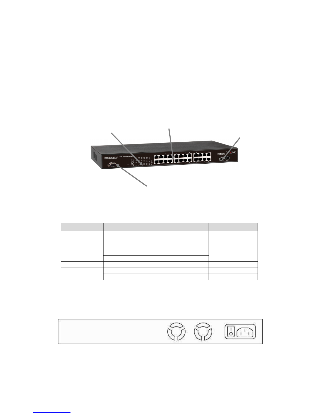
Front Panel
The front panel of the L2 management switch consists of 24 10/100/1000 Base-TX RJ-45
ports and 2 gigabit uplink SFP ports. The LED Indicators are also located on the front
panel.
LED Indicators
The LED Indicators present real-time information of systematic operation status. The
following table provides description of LED status and their meaning.
LED Color / Status Description No. of LEDs
Power Amber On Power on
Power
Green On Link Up
10/100/1000M
Green Blinking Data Activating
24(1~24)
PoE Amber On PD is connected 24 (1~24)
Green On linked to Power Device
25~26
SFP
Green Blinking Data Activating 25~26
Rear Panel
The 3-pronged power plug is placed at the rear panel of the switch right side shown as
below.
Hardware
Installation
LED Display
Uplink SFP Port
RJ-45 Port
RS-232 Console

14
The switch is usually mounted in the 19” rack, the rack is usually installed in IT room or other
secured place. The switch supports AC power input, PoE delivery and rackmount mounting.
Make sure all the power cables, Ethernet cables, screws and the air circulation are well
prepared and installed as below description.
AC Power Input
Connect the attached power cord to the AC power input connector, the available AC power
input is range from 100-264VAC.
There are 2 power modules inside the switch, each of them support up to 250W. With our
current sharing technology, the 2 modules can deliver power up to 500W.
Ethernet cable Request
The wiring cable types are as below.
10 Base-T: 2-pair UTP/STP Cat. 3, 4, 5 cable, EIA/TIA-568 100-ohm (Max. 100m)
100 Base-TX: 2-pair UTP/STP Cat. 5 cable, EIA/TIA-568 100-ohm (Max. 100m)
1000 Base-T: 4-pair UTP/STP Cat. 5 cable, EIA/TIA-568 100-ohm (Max. 100m)
PoE: To delivery power without problem, the Cat 5e and Cat 6 cable is suggested. The high
quality Ethernet cable reduces the lost while power transmission.
SFP Installation
While install the SFP transceiver, make sure the SFP type of the 2 ends is the same and the
transmission distance, wavelength, fiber cable can meet your request. It is suggested to
purchase the SFP transceiver with the switch provider to avoid any incompatible issue.
The way to connect the SFP transceiver is to Plug in SFP fiber transceiver fist. The SFP
transceiver has 2 plug for fiber cable, one is TX (transmit), the other is RX (receive).
Cross-connect the transmit channel at each end to the receive channel at the opposite end.
Rackmount Installation
Attach the brackets to the device by using the screws provided in the Rack Mount kit.
Mount the device in the 19 rack by using four rack-mounting screws provided by the rack
manufacturer.
3. Preparation for Management
The switch provides both in-band and out-band configuration methods.
Out-band Management: You can configure the switch via RS232 console cable if you don’t
attach your admin PC to your network, or if you lose network connection to your switch. It
wouldn’t be affected by network performance. This is so-called out-band management.
In-Band Management: You can remotely manage the switch via the Web browser, such as
Microsoft Internet Explorer, or Mozila, to configure and interrogate the switch from anywhere
on the network.
Following topics are covered in this chapter:
3.1 Preparation for Serial Console
3.2 Preparation for Web Interface
3.1 Preparation for Serial Console
In the package, there is one RS-232 console cable. Please attach one end of the console
cable to your PC COM port, the other end to the console port of the switch.
1. Go to Start -> Program -> Accessories -> Communication -> Hyper Terminal
2. Give a name to the new console connection.
3. Choose the COM name
4. Select correct serial settings. The serial settings of the switch are as below:
Baud Rate: 115200 / Parity: None / Data Bit: 8 / Stop Bit: 1
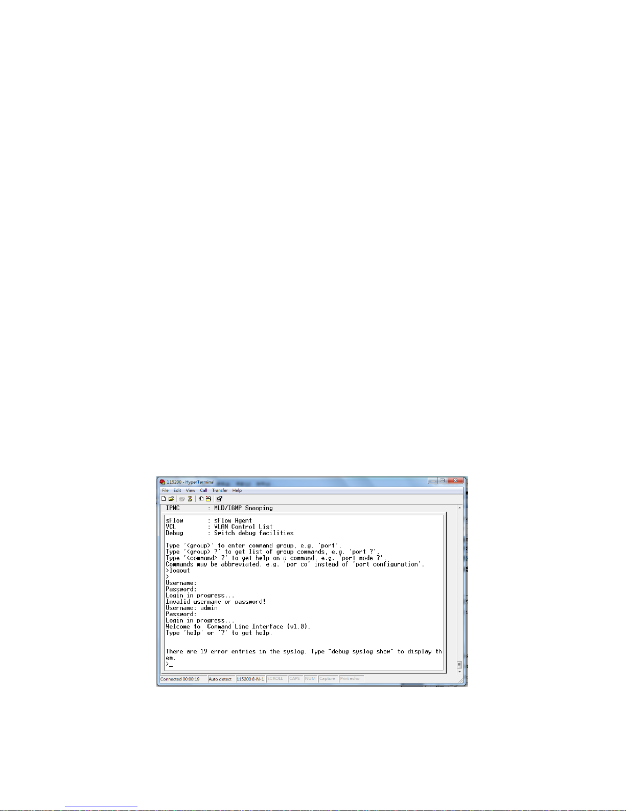
5. After connected, you can see Switch login request.
6. Login the switch. The default username is “admin”, password, “admin”.
Figure 3-1 Hyper Terminal Console Screen
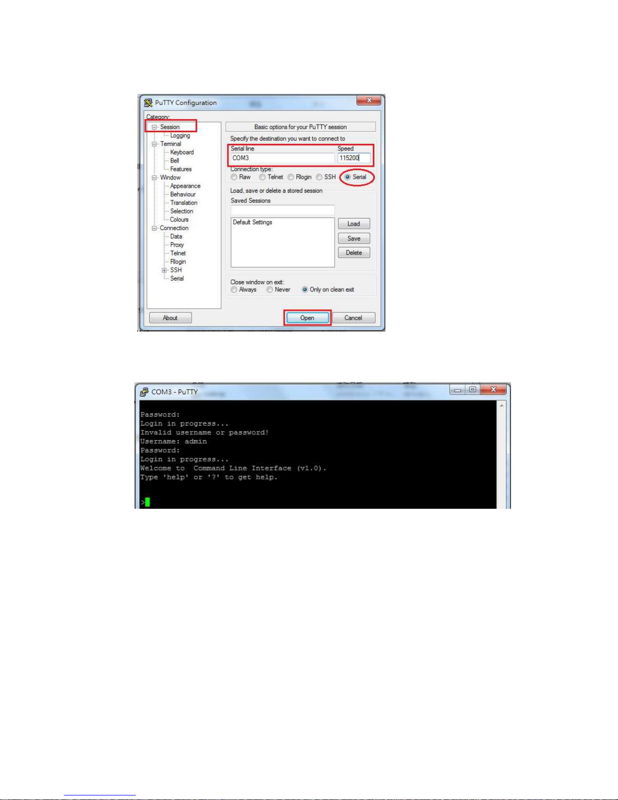
Note: The Win 7 or later OS version doesn't provide Console Terminal tool, please
download the tool, Hyper Terminal from Microsoft web site or other terminal tools, such as
PuTTY for console connection. Type Hyper Terminal or Putty in Google web site, thus you
can find link to download it.
16
Figure 3-2 Putty Configuration
Figure 3-3 Putty Login Screen
3.2 Preparation for Web Interface
The web management page allows you to use a standard web-browser such as Microsoft
Internet Explorer, Google Chrome or Mozila Firefox, to configure and interrogate the switch
from anywhere on the network.
Before you attempt to use the web user interface to manage switch operation, verify that
your Switch is properly installed on your network and that every PC on this network can
access the switch via the web browser.
1. Verify that your network interface card (NIC) is operational, and that your operating
system supports TCP/IP protocol.
2. Wire the switch power and connect your computer to the switch.
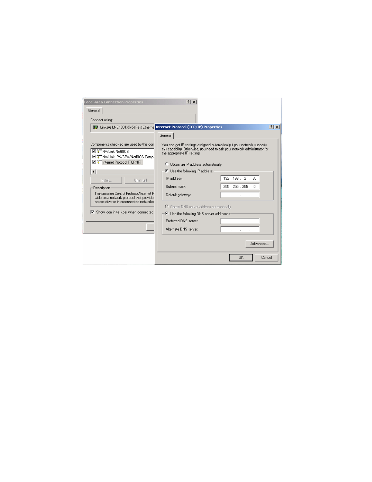
17
3. The switch default IP address is 192.168.2.1. The Switch and the connected PC should
locate within the same IP Subnet.
4. Change your computer's IP address to 192.168.2.XX or other IP address which is located
in the 192.168.2.x (For example: IP Address: 192.168.2.30; Subnet Mask: 255.255.255.0)
subnet.
Launch the web browser and Login.
5. Launch the web browser (Internet Explorer or Mozila Firefox) on the PC.
6. Type http://192.168.2.1 (or the IP address of the switch). And then press Enter.
7. The login screen will appear next.
8. Key in the password. Default user name and password are both admin.
If you can't login the switch, the following steps can help you to identify the problem.
1. Switch to DOS command mode and type the "ipconfig" to check the NIC's setting. Type the
"ping 192.168.2.1" to verify a normal response time.
2. Check the security & firewall settings of your computer.
3. Try different Web-browser, like the Mozila.
3.3 Preparation for Telnet/SSH Interface
If your Window OS is Win XP, Win 2000 or early version, you can access the Telnet console by
default command. If your OS is Window 7 or later version, please download the terminal tool,
such as HyperTeminal or Putty.
The switch support both Telnet and SSH console. The SSH console can be treated as secured
Telnet connection, need to enable the SSH feature in "Security / Switch / SSH".
Tradition way for Telnet Connection
1. Go to Start -> Run -> cmd. And then press Enter
2. Type the Telnet 192.168.2.1 (or the IP address of the switch). And then press Enter.
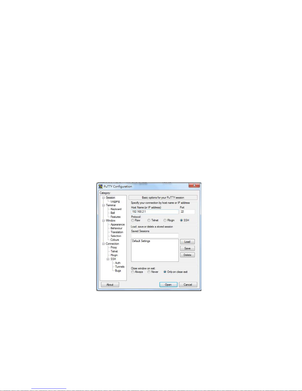
Access Telnet or SSH by Terminal tool, Putty.
1. Open Telnet/SSH Client/PuTTY
In the Session configuration, choose the Telnet/SSH in Protocol field.
In the Session configuration, enter the Host Name (IP Address of your switch) and Port
number (default Telnet =23, SSH = 22).
Then click on “Open” to start the SSH session console.
2. After click on Open, then you can see the cipher information in the popup screen. Press Yes
to accept the Security Alert.
If you choose Telnet connection, there is no such cipher information and window. It goes to
next step directly.
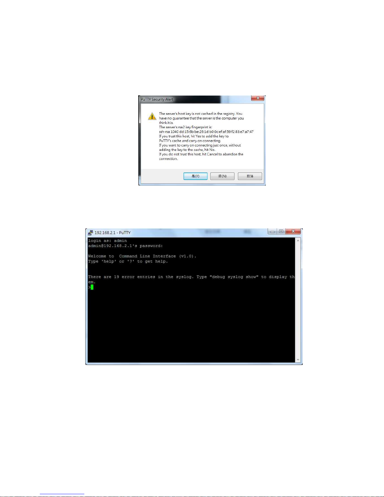
19
3. After few seconds, the Telnet/SSH connection is established, the login page of Telnet/SSH
is the same as console. The command line of Telnet, SSH and console are all the same.
4. Feature Configuration - Web UI
The switch provides Abundant software features, after login the switch, you can start
configuring the settings or monitoring the status. This is one question market on the right top
of the screen, you can also click the question mark to get help from the system.
Following are the Web UI configuration guide for your reference.
4.1 System Configuration
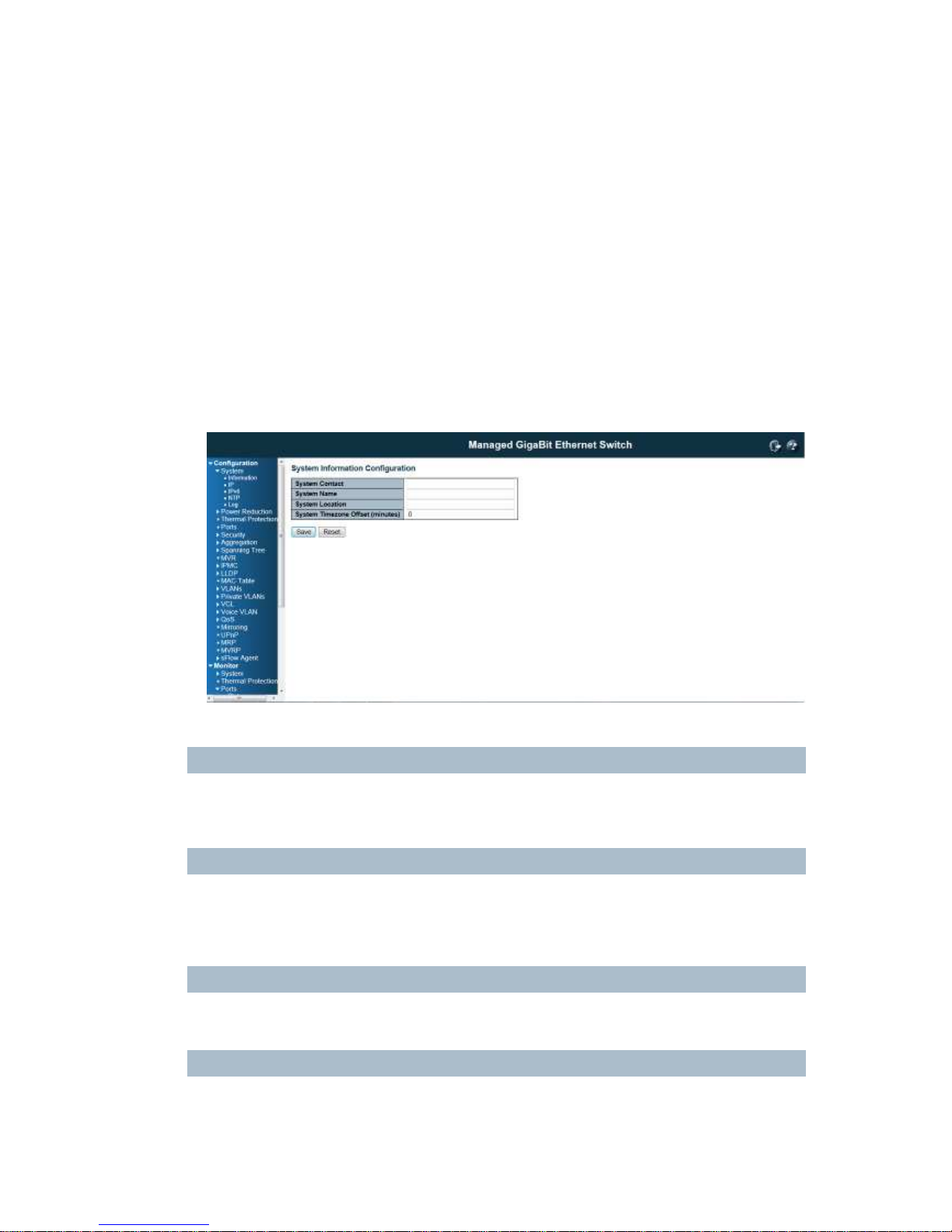
4.1.1 System Information
This page shows the system information and allows you to configure the new settings.
System Contact
The
textual identification of the contact person for this managed node, together with information on how
to contact this person. The allowed string length is 0 to 255, and the allowed content is the ASCII
characters from 32 to 126.
System Name
An administratively assigned name for this managed node. By convention, this is the node's fully-qualified
domain name. A domain name is a text string drawn from the alphabet (A-Za-z), digits (0-9), minus sign
(-). No space characters are permitted as part of a name. The first character must be an alpha character.
And the first or last character must not be a minus sign. The allowed string length is 0 to 255.
System Location
The physical location of this node(e.g., telephone closet, 3rd floor). The allowed string length is 0 to 255,
and the allowed content is the ASCII characters from 32 to 126.
Time zone Offset
Provide the time zone offset relative to UTC/GMT.
The offset is given in minutes east of GMT. The valid range is from -720 to 720 minutes.
21
Buttons:
Save: Click to save changes
Reset: Click to undo any changes made locally and revert to previously saved values
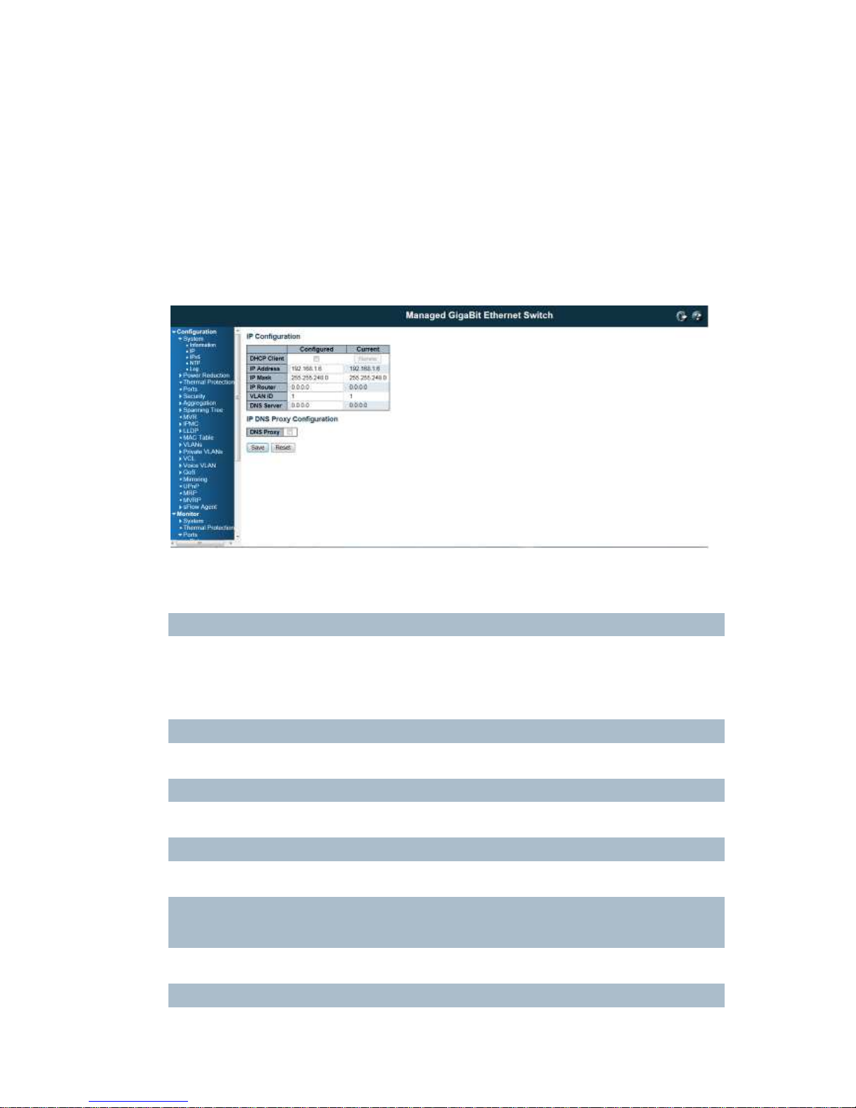
4.1.2 IP Configuration:
Configure the switch-managed IP information on this page.
The Configured column is used to view or change the IP configuration.
The Current column is used to show the active IP configuration.
DHCP Client
Enable the DHCP client by checking this box. If DHCP fails and the configured IP address is zero, DHCP
will retry. If DHCP fails and the configured IP address is non-zero, DHCP will stop and the configured IP
settings will be used. The DHCP client will announce the configured System Name as hostname to
provide DNS lookup.
IP Address
Provide the IP address of this switch in dotted decimal notation.
IP Mask
Provide the IP mask of this switch dotted decimal notation.
IP Router
Provide the IP address of the router in dotted decimal notation.
NTPProvide the IP address of the NTP Server in dotted decimal notation.
DNS Server
Provide the IP address of the DNS Server in dotted decimal notation.
VLAN ID
22
Provide the managed VLAND ID. The allowed range is 1 to 4095.
DNS Proxy
When DNS proxy is enabled, the switch will relay DNS requests to the current configured DNS server on
the switch, and reply as a DNS resolver to the client device on the network.
Buttons
Save: Click to save changes
Reset: Click to undo any changes made locally and revert to previously saved values
Renew: Click to renew DHCP. This button is only available if DHCP is enabled.
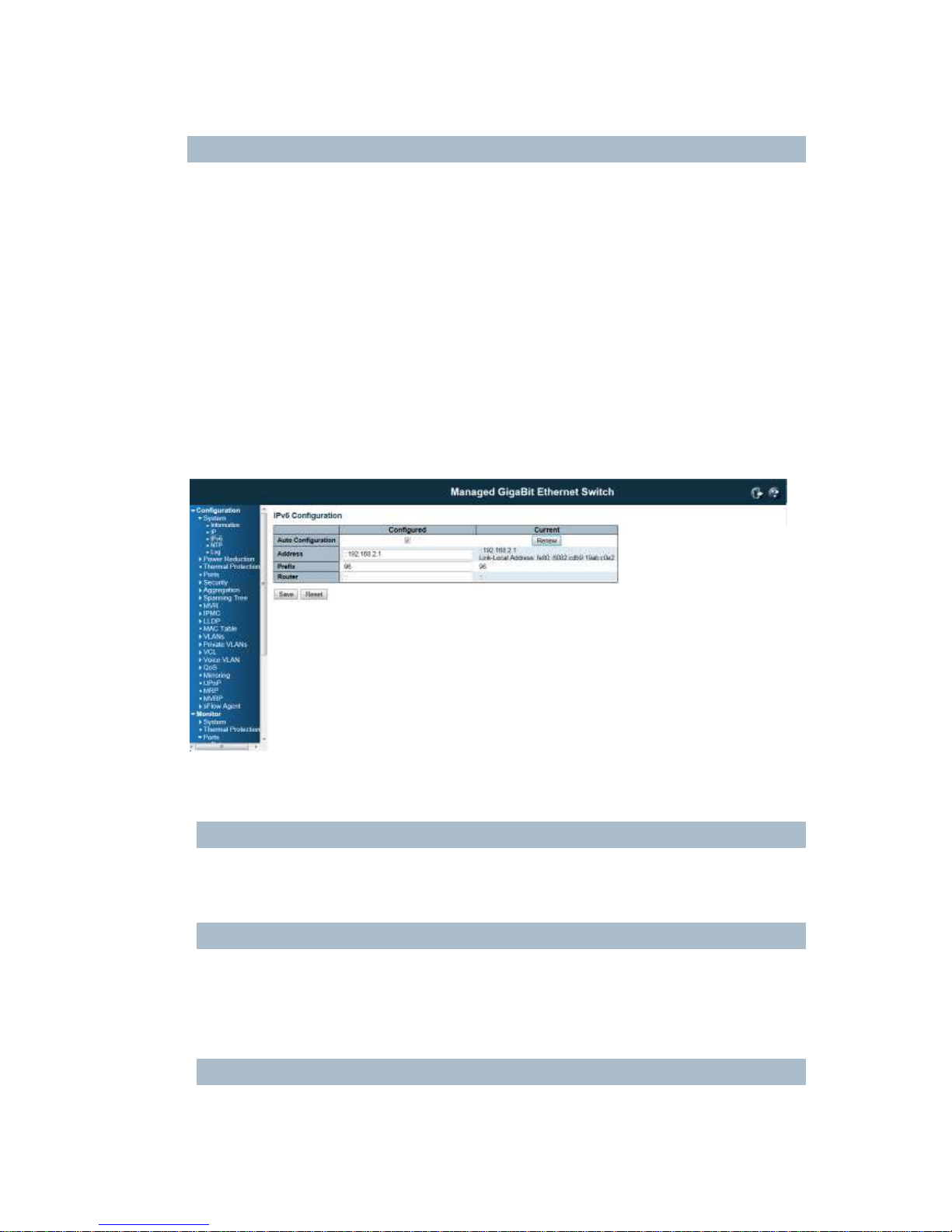
4.1.3 IPv6 Configuration
Configure the switch-managed IPv6 information on this page:
The Configured column is used to view or change the IPv6 configuration.
The Current column is used to show the active IPv6 configuration.
Auto Configuration
Enable IPv6 auto-configuration by checking this box. If fails, the configured IPv6 address is zero. The
router may delay responding to a router solicitation for a few seconds, the total time needed to complete
auto-configuration can be significantly longer.
Address
Provide the IPv6 address of this switch. IPv6 address is in 128-bit records represented as eight fields of
up to four hexadecimal digits with a colon separating each field (:). For example,
'fe80::215:c5ff:fe03:4dc7'. The symbol '::' is a special syntax that can be used as a shorthand way of
representing multiple 16-bit groups of contiguous zeros; but it can only appear once. It can also
represent a legally valid IPv4 address. For example, '::192.1.2.34'.
Prefix
Provide the IPv6 Prefix of this switch. The allowed range is 1 to 128.
23
Router
Provide the IPv6 gateway address of this switch. IPv6 address is in 128-bit records represented as eight
fields of up to four hexadecimal digits with a colon separating each field (:). For example,
'fe80::215:c5ff:fe03:4dc7'.
The symbol '::' is a special syntax that can be used as a shorthand way of representing multiple 16-bit
groups of contiguous zeros; but it can only appear once. It can also represent a legally valid IPv4
address. . For example, '::192.1.2.34'.
Buttons
Save: Click to save changes
Reset: Click to undo any changes made locally and revert to previously saved values
Renew: Click to renew IPv6 AUTOCONF. This button is only available if IPv6 AUTOCONF is enabled.
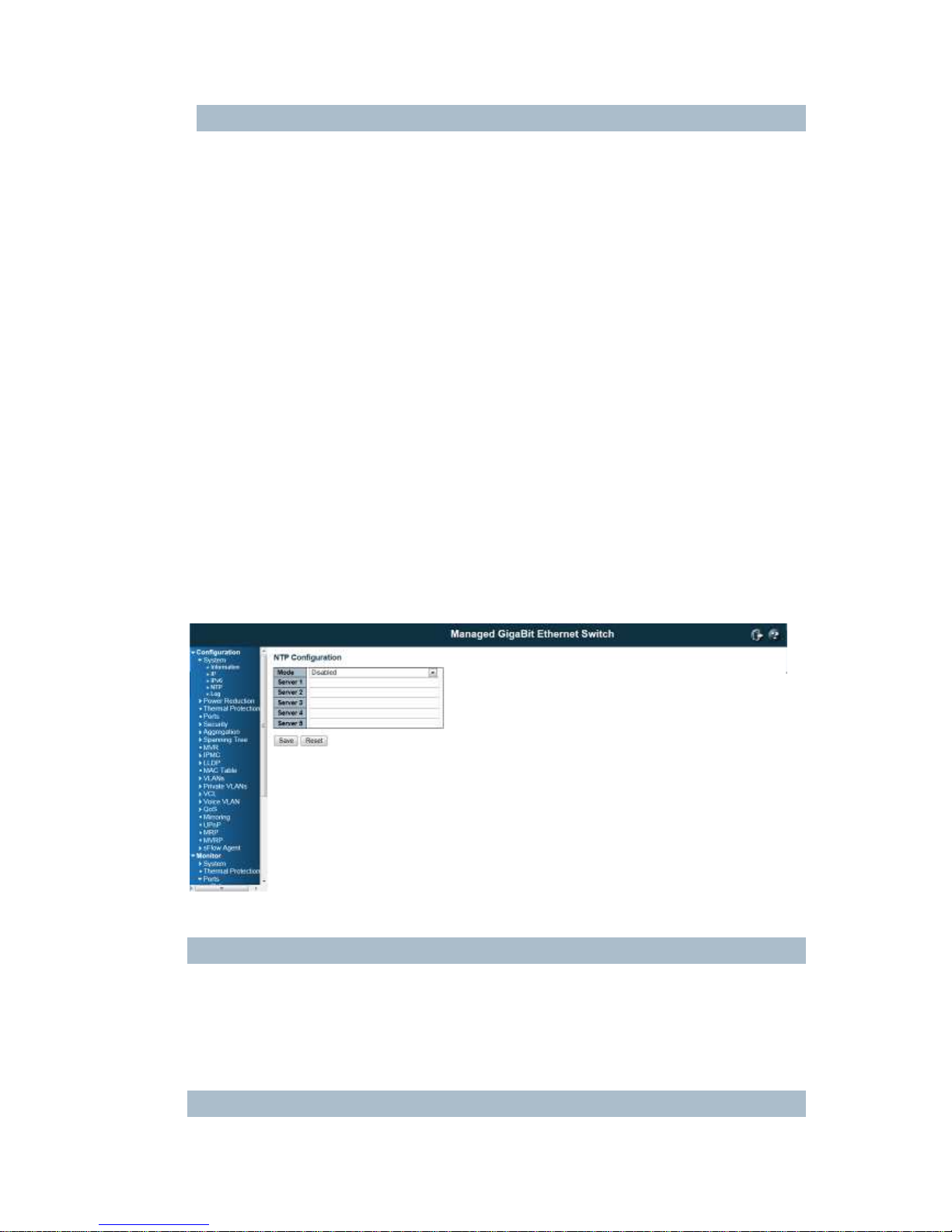
4.1.4 NTP Configuration:
NTP is short of Network Time Protocol. Network Time Protocol (NTP) is used to synchronize time
clocks on the internet. You can configure NTP Servers' IP address here to synchronize the clocks of the
remote time server on the network.
This page indicates the NTP mode operation:
Mode
The Possible modes are:
Enable NTP mode operation. When NTP mode operation is enabled, the agent forwards NTP messages
between the clients and the server when they are not on the same subnet domain.
Disable NTP mode operation.
Server #

24
Provide the NTP IPv4 or IPv6 address of this switch. IPv6 address is in 128-bit records represented as
eight fields of up to four hexadecimal digits with a colon separating each field (:). For example,
'fe80::215:c5ff:fe03:4dc7'. The symbol '::' is a special syntax that can be used as a shorthand way of
representing multiple 16-bit groups of contiguous zeros; but it can only appear once. It can also represent
a legally valid IPv4 address. For example, '::192.1.2.34'.
Buttons
Save: Click to save changes
Reset: Click to undo any changes made locally and revert to previously saved values
4.1.5 System Log Configuration:
System Log is useful to provide system administrator monitor switch events history. The switch
supports syslog server mode. User can install the syslog server in one computer, then
configure the server address and event types in the switch's system log configuration. When
the events occur, the switch will send information or warning message to the syslog server.
The administrator can analysis the system logs recorded in the syslog server to find out the
cause of the issues.
The switch Web UI allows you to Enable the Syslog Server, assign the IP address and assign
the syslog level.
Server Mode
Indicates the server mode operation. When the mode operation is enabled, the syslog message will send
out to syslog server. The syslog protocol is based on UDP communication and received on UDP port 514
and the syslog server will not send acknowledgments back sender since UDP is a connectionless
protocol and it does not provide acknowledgments. The syslog packet will always send out even if the
syslog server does not exist. Possible modes are:
Enable server mode operation.
Disable server mode operation.
Server Address
Indicates the IPv4 host address of syslog server. If the switch provide DNS feature, it also can be a host
name.

25
Syslog Level
Indicates what kind of message will send to syslog server.
Possible modes are:
Info: Send information, warnings and errors.
Warning: Send warnings and errors.
Error: Send errors.
Buttons
Save: Click to save changes
Reset: Click to undo any changes made locally and revert to previously saved values
4.2 Power Reduction
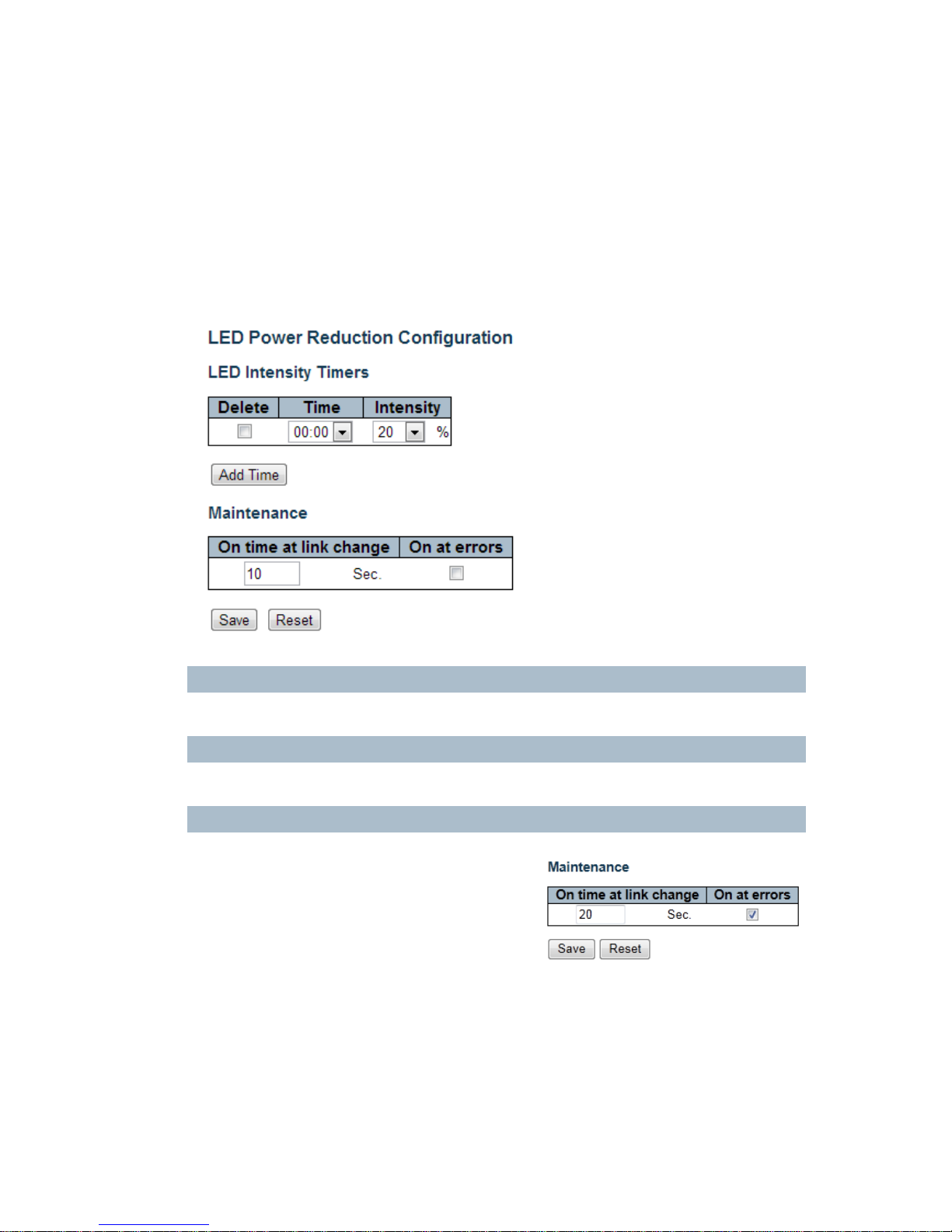
4.2.1 LED Power Reduction Configuration
LEDs Intensity
The LEDs power consumption can be reduced by lowering the LEDs intensity. LEDs intensity could for
example be lowered during night time, or they could be turn completely off. It is possible to configure 24
different hours of the day, at where the LEDs intensity should be set.
Time
The time at which the LEDs intensity shall be set. The time setting is step by one hour.
Intensity
The LEDs intensity (100% = Full power, 0% = LED off)
Maintenance Time
When a network administrator does maintenance of the
switch (e.g. adding or moving users) he might want to
have full LED intensity during the maintenance period .
Therefore it is possible to specify that the LEDs shall use
full intensity a specific period of time. Maintenance Time
is the number of seconds that the LEDs will have full
intensity after either a port has changed link state, or the
LED pushbutton has been pushed.
Buttons
Save: Click to save changes
Reset: Click to undo any changes made locally and revert to previously saved values
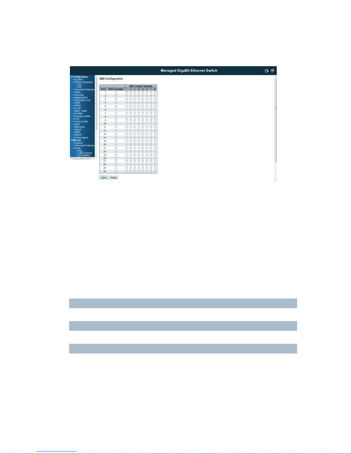
4.2.2 EEE Configuration:
This page allows the user to inspect and configure the current EEE port settings:
EEE is a power saving option that reduces the power usage when there is very low traffic utilization (or no
traffic).
EEE works by powering down circuits when there is no traffic. When a port gets data to be transmitted all
circuits are powered up. The time it takes to power up the circuits is named wakeup time. The default
wakeup time is 17 us for 1Gbit links and 30 us for other link speeds. EEE devices must agree upon the
value of the wakeup time in order to make sure that both the receiving and transmitting device has all
circuits powered up when traffic is transmitted. The devices can exchange information about the devices
wakeup time using the LLDP protocol.
For maximizing the power saving, the circuit isn't started at once transmit data are ready for a port, but is
instead queued until 3000 bytes of data are ready to be transmitted. For not introducing a large delay in
case that data less then 3000 bytes shall be transmitted, data are always transmitted after 48 us, giving a
maximum latency of 48 us + the wakeup time.
If desired it is possible to minimize the latency for specific frames, by mapping the frames to a specific
queue (done with QOS), and then mark the queue as an urgent queue. When an urgent queue gets data
to be transmitted, the circuits will be powered up at once and the latency will be reduced to the wakeup
time.
Port
The switch port number of the logical EEE port.
EEE Enabled
Controls whether EEE is enabled for this switch port.
EEE Urgent Queues
Queues set will activate transmision of frames as soon as any data is available. Otherwise the queue will
postpone the transmsion until 3000 bytes are ready to be transmitted.
Buttons
Save: Click to save changes
Reset: Click to undo any changes made locally and revert to previously saved values
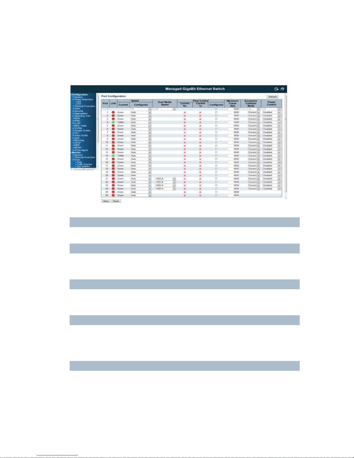
4.3 Port Configuration:
This page displays current port configurations and link status. Some of the Ports' settings can also be
configured here.
Port
This is the port number for this row.
Link
The current link state is displayed graphically.
Green indicates the link is up and red that it is down.
Current Link Speed
Provides the current link speed of the port.
Ex: 1Gfdx: 1G indicates the Gigabit Speed, fdx indicates the Full Duplex Mode.
Configured Link Speed
Select any available link speed for the given switch port.
Auto Speed: selects the highest speed that is compatible with a link partner.
Disabled: disables the switch port operation.
Fiber Speed
Configure speed for fiber port.
Note: Port speed for the Copper ports will automatically be set to Auto when dual media is selected.
Disable SFPs (Copper port only).
SFP-Auto automatically determines the speed at the SFP.

29
Note: There is no standardized way to do SFP auto detect, so here it is done by reading the SFP rom.
Due to the missing standardized way of doing SFP auto detect some SFPs might not be detectable.
1000-X force SFP speed to 1000-X.
100-FX force SFP speed to 100-FX.
Flow Control
When Auto Speed is selected on a port, this section indicates the flow control capability that is advertised
to the link partner.
When a fixed-speed setting is selected, that is what is used. The Current Rx column indicates whether
pause frames on the port are obeyed, and the Current Tx column indicates whether pause frames on the
port are transmitted. The Rx and Tx settings are determined by the result of the last Auto-Negotiation.
Check the configured column to use flow control. This setting is related to the setting for Configured Link
Speed.
Maximum Frame Size
Enter the maximum frame size allowed for the switch port, including FCS.
The switch supports up to 9K Jumbo Frame.
Excessive Collision Mode
Configure port transmit collision behavior.
Discard: Discard frame after 16 collisions (default).
Restart: Restart backoff algorithm after 16 collisions.
Power Control
The Usage column shows the current percentage of the power consumption per port. The Configured
column allows for changing the power savings mode parameters per port.
Disabled: All power savings mechanisms disabled.
ActiPHY: Link down power savings enabled.
PerfectReach: Link up power savings enabled.
Enabled: Both link up and link down power savings enabled.
Buttons
Save: Click to save changes
Reset: Click to undo any changes made locally and revert to previously saved values
Refresh: Click to refresh the page. Any changes made locally will be undone.
4.4 Security Configuration:
The Security Configuration feature includes 3 sub-titles, Switch, Network and AAA.
4.4.1 Security / Switch
The switch settings includes User Database, Privilege Levels, Authentication Method, SSH, HTTPs, Access
Management, SNMP and RMON setting. Following are the topic and configuration guide.
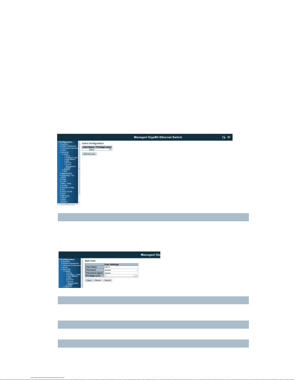
4.4.1.1 Security / Switch / Users Configuration
This page provides an overview of the current users. Currently the only way to login as another user on the
web server is to close and reopen the browser.
This page configures a user: This is also a link to Add User & Edit User
Add New User/Edit User
Click "Add New User", the configuration page goes to "Add User" screen. You can see the User Setting
table, follow the below instruction to fill the table.
Click the created User Name, the page goes to "Edit User" screen, you can change the settings on it.
User Name
A string identifying the user name that this entry should belong to. The allowed string length is 1 to 32.
The valid user name is a combination of letters, numbers and underscores.
Password
The password of the user. The allowed string length is 0 to 32.
Privilege Level
 Loading...