

Vidikron VP-103VHD, VP-5000VHDA, VP-6500VHDa, VP-5000VHD, VP-6500VHD User Manual 2

HIGH DEFINITION PLASMA DISPLAYS
Models VP-5000VHD, VP-5000VHDa,
VP-6500VHD, VP-6500VHDa
and VP-103VHD
INSTALLATION/OPERATION MANUAL


THREE YEAR LIMITED WARRANTY
For Plasma Displays
from Vidikron, a business of Runco International, LLC (“Vidikron”)
Congratulations on your purchase of a Vidikron video product and welcome to the Vidikron family! With proper installation, setup
and care, you should enjoy many years of unparalleled video performance.
This is a LIMITED WARRANTY as defined in the Magnuson-Moss Warranty Act. Please read it carefully and retain it with your other
important documents.
WHAT IS COVERED UNDER THE TERMS OF THIS LIMITED WARRANTY:
The following Vidikron plasma display models are covered under this Limited Warranty:
VP-5000VHD, VP-5000VHDa, VP-6500VHD, VP-6500VHDa and VP-103VHD (“Product” individually and “Products” collectively).
SERVICE LABOR: Vidikron will pay for service labor at an Authorized Service Center when needed as a result of manufacturing
defect for a period of three (3) years from the date of delivery to the initial end user (excluding the plasma glass panel).
PARTS (not including plasma glass panel): Vidikron will provide new or rebuilt replacement parts for the parts that fail due to
defects in materials or workmanship for a period of three (3) years from the effective date of delivery to the initial end user. Such
replacement parts are then subsequently warranted for the remaining portion (if any) of the original warranty period.
PLASMA GLASS PANEL: Vidikron will pay for service labor at an Authorized Service Center when needed as a result of a
manufacturing defect for a period of one (1) year from the effective date of delivery to the initial end user. In addition, Vidikron will
provide new or rebuilt replacement parts for the parts that fail due to defects in materials or workmanship for a period of one (1)
year from the effective date of delivery to the initial end user. Such replacement parts are then subsequently warranted for the
remaining portion (if any) of the original warranty period.
IMINAR
Y
L
WHAT IS NOT COVERED UNDER THE TERMS OF THIS LIMITED WARRANTY:
Image burn-in on plasma display panels is specifically excluded from coverage under this Limited Warranty. Image burn-in is the
result of misuse of the Product and therefore cannot be repaired under the terms of this Limited Warranty.
Normal viewing material such as television/satellite broadcasts, videotape or DVDs (not put into pause for extended periods of
time) will not cause damage to your display under normal conditions. Many DVD players are also equipped with screen savers for
this reason.
TO AVOID IMAGE RETENTION (Burn-in): Please ensure that still images are left on your plasma display panel for no more than a
few minutes. Also ensure that images displayed in the 4:3 aspect ratio mode (black or gray stripes, but no picture information is
present on the left and right edges of the screen) are used as infrequently as possible. This will prevent permanent image burns on
your plasma display panel, which can be seen permanently under certain conditions once burn-in has occurred.
PRE
The types of images to avoid include video games, still images and computer screens with stationary tool bars and icons. (This is
why computers are equipped with screen savers – to prevent still images from burning into the monitor’s phosphors after being
displayed continuously for an extended period of time).
This Limited Warranty only covers failure due to defects in materials and workmanship that occur during normal use and does not
cover normal wear and tear nor any Product on which the serial number has been defaced, modified, or removed. This Limited
Warranty does not cover: cabinets or any appearance items; failure resulting from accident, misuse, abuse, neglect, mishandling,
misapplication, or faulty or improper installation or setup adjustments; improper maintenance; alteration; improper use of any
input signal; damage due to lightning or power line surges, spikes and brownouts; damage that occurs during shipping or transit;
damage that is attributed to acts of God; customer caused defects; or rental costs incurred due to Product failure. In the case of
remote control units, damage resulting from leaking, old, damaged or improper batteries is also excluded from coverage under
this Limited Warranty.
Vidikron PlasmaView VHD Installation/Operation Manual iii

CAUTION: THIS LIMITED WARRANTY ONLY COVERS VIDIKRON PRODUCTS PURCHASED FROM AUTHORIZED VIDIKRON DEALERS.
ALL OTHER PRODUCTS ARE SPECIFICALLY EXCLUDED FROM COVERAGE UNDER THIS WARRANTY. MOREOVER, DAMAGE
RESULTING DIRECTLY OR INDIRECTLY FROM IMPROPER INSTALLATION OR SETUP IS SPECIFICALLY EXCLUDED FROM COVERAGE
UNDER THIS LIMITED WARRANTY. IT IS IMPERATIVE THAT INSTALLATION AND SETUP WORK BE PERFORMED ONLY BY AN
AUTHORIZED VIDIKRON DEALER TO PROTECT YOUR RIGHTS UNDER THIS WARRANTY. THIS WILL ALSO ENSURE THAT YOU ENJOY
THE FINE PERFORMANCE OF WHICH YOUR VIDIKRON PRODUCT IS CAPABLE WHEN INSTALLED AND CALIBRATED BY AN
AUTHORIZED VIDIKRON DEALER.
RIGHTS, LIMITS AND EXCLUSIONS:
THE FOREGOING DESCRIBED WARRANTIES ARE THE ONLY WARRANTIES THAT APPLY TO THE PRODUCTS. VIDIKRON MAKES NO
OTHER WARRANTY OR REPRESENTATION AND HEREBY DISCLAIMS ALL OTHER WARRANTIES, EXPRESS OR IMPLIED, INCLUDING,
BUT NOT LIMITED TO, THE IMPLIED WARRANTIES OF MERCHANTABILITY AND FITNESS FOR A PARTICULAR PURPOSE.VIDIKRON’S
LIABILITY RELATED TO THE PRODUCT IS LIMITED TO THE COST OF THE APPLICABLE REMEDY AS NOTED ABOVE. IN NO EVENT
SHALL VIDIKRON BE LIABLE FOR:
• DAMAGE TO OTHER PROPERTY CAUSED BY ANY DEFECTS IN THE PRODUCT, DAMAGES BASED UPON INCONVENIENCE, LOSS OF
USE OF THE PRODUCT, LOSS OF TIME, LOSS OF PROFITS, LOSS OF BUSINESS OPPORTUNITY, LOSS OF GOODWILL, INTERFERENCE
WITH BUSINESS RELATIONSHIPS, OR OTHER COMMERCIAL LOSS, EVEN IF ADVISED OF THE POSSIBILITY OF SUCH DAMAGES;
• ANY OTHER DAMAGES, WHETHER INCIDENTAL, CONSEQUENTIAL OR OTHERWISE;
• ANY CLAIM AGAINST THE CUSTOMER BY ANY OTHER PARTY; OR
• ANY VERBAL WARRANTY ASSURANCES MADE BY A VIDIKRON EMPLOYEE OR A VIDIKRON AUTHORIZED DEALER THAT
CONFLICTS WITH OR ENHANCES THE WRITTEN WARRANTY INCLUDED HEREIN.
Y
EFFECTIVE WARRANTY DATE:
This Limited Warranty begins on the date of delivery to the end user. For your convenience, keep the original bill of sale as
evidence of the purchase date.
CONTACT AN AUTHORIZED SERVICE CENTER TO OBTAIN SERVICE:
Repairs made under the terms of this Limited Warranty covering your Vidikron Product will be performed at the location of the
Product, during usual working hours, provided that the location of the Product is within normal operating distance from an
Authorized Vidikron Service Center. In some instances it may be necessary for the Product to be returned to the Vidikron factory for
repairs. If, solely in Vidikron’s judgment, location of Product to be repaired is beyond normal operating distance of the closest
Authorized Vidikron Service Center, or the repair requires the unit be returned to the Vidikron factory, it is the owner’s
responsibility to arrange for shipment of the Product for repair. These arrangements must be made through the selling Vidikron
Dealer. If this is not possible, contact Vidikron directly for a Return Authorization number and shipping instructions. Vidikron will
return Product with transportation prepaid in the United States, unless no Product defect is discovered. In that instance, shipping
costs will be the responsibility of the Product owner.
PRE
IMINAR
L
iv Vidikron PlasmaView VHD Installation/Operation Manual

COPYRIGHT AND TRADEMARKS:
© Copyright 2008 Runco International, LLC (“Runco”). This document contains proprietary information protected by copyright,
trademark and other intellectual property laws. All rights are reserved. No part of this manual may be reproduced by any
mechanical, electronic or other means, in any form, without prior written permission of Runco.
The trademarks reporduced in this Vidikron Owner’s Manual and used on the Vidikron Products are either owned by Runco or are
licensed by Runco. You may not reproduce or use the trademarks without the prior written consent of Runco.
THX and the THX logo are trademarks of THX Ltd. which may be registered in some jurisdictions. All rights reserved.
Vidikron Products are manufactured under one or more of the following patents: US. Patent 6755540 and Other Patents Pending.
ADDITIONAL INFORMATION:
To locate the name and address of the nearest Authorized Vidikron Service Center, or for additional information about this Limited
Warranty, please call or write:
VIDIKRON, c/o RUNCO INTERNATIONAL, LLC
1195 NW Compton Drive
Beaverton, OR 97006-1992
Ph: (503) 748-5799
Fax: (503) 748-8161
Toll Free: (888) 4VIDIKRON (888-484-3457)
IMINAR
Y
L
PRODUCT INFORMATION
RETAIN FOR YOUR RECORDS
_________________________________________________________ ________________________________________
Model Purchased Date
____________________________________________________________________________________________________________
PRE
Serial Number
____________________________________________________________________________________________________________
Vidikron Authorized Dealer Name
____________________________________________________________________________________________________________
Address
____________________________________________ __________________ ________________________
City State/Province Postal Code
____________________________________________ _______________________________________________________
Phone Fax
Vidikron PlasmaView VHD Installation/Operation Manual v
Important Safety Instructions
Thank you for your purchase of this quality Vidikron video product! It has been designed to provide you with the quality of video
that is expected in a home theater. For the best performance, please read this manual carefully as it is your guide through the
menus and operation.
WAR NING
CAUTION
RISK OFELECTRIC SHOCK
DO NOTOPEN
TO REDUCE THE RISK OF ELECTRIC SHOCK
DO NOT REMOVE COVER (OR BACK)
NO USER SERVICEABLE PARTS INSIDE.
REFER SERVICING TO QUALIFIED
1. Read these instructions.
2. Keep these instructions.
3. Heed all warnings.
4. Follow all instructions.
5. Do not use this apparatus near water.
6. Clean only with a dry cloth.
7. Do not block any of the ventilation openings. Install in accordance with the manufacturer’s instructions.
8. Do not install near any heat sources such as radiators, heat registers, stoves, or other apparatus (including amplifiers) that
produce heat.
9. Do not defeat the safety purpose of the polarized or grounding type plug. A polarized plug has two blades with one wider
than the other. A grounding type plug has two blades and a third grounding prong. The wide blade or the third prong is
provided for your safety. When the provided plug does not fit into your outlet, consult an electrician for the replacement of the
obsolete outlet.
10. Protect the power cord from being walked on or pinched particularly at plugs, convenience receptacles and the point where
they exit from the apparatus.
11. Only use the attachments/accessories specified by the manufacturer.
12. Use only with a cart, stand, tripod, bracket or table specified by the manufacturer or sold with the apparatus. When
a cart is used, use caution when moving the cart/apparatus to avoid injury from tip-over.
CAUTION:
SERVICE PERSONNEL.
PRE
This symbol is intended to alert the user to the presence of
uninsulated “dangerous voltage” within the product’s enclosure that
may be of sufficient magnitude to constitute a risk of electric shock.
This symbol is intended to alert the user to the presence of important
operating and maintenance (servicing) instructions in the literature
accompanying the appliance.
Y
IMINAR
L
13. Unplug this apparatus during lightning storms or when unused for long periods of time.
14. Refer all servicing to qualified service personnel. Servicing is required when the apparatus has been damaged in
any way, such as power supply cord or plug is damaged, liquid has been spilled or objects have fallen into the apparatus, the
apparatus has been exposed to rain or moisture, does not operate normally, or has been dropped.
15. Keep the packing material in case the equipment should ever need to be shipped.
vi Vidikron PlasmaView VHD Installation/Operation Manual

Compliance Information
DECLARATION OF CONFORMITY:
Manufacturer’s Name: Runco International, LLC
Manufacturer’s Address: 1195 NW Compton Drive, Beaverton, OR 97006-1992
hereby declares that the Products’ Model Numbers:
VP-5000VHD, VP-5000VHDa, VP-6500VHD, VP-6500VHDa and VP-103VHD
conform with the provisions of:
Council Directive 2004/108/EC on Electromagnetic Compatibility;
EN 55022 “Limits and methods of measurements of radio interference characteristics of information technology equipment” 1998;
EN 55024 “Limits and methods of measurements of immunity characteristics of information technology equipment” 1998;
Including:
• EN 61000-4-2 “Electromagnetic compatibility (EMC) Part 4: Testing and measurement techniques Section 2: Electrostatic
discharge immunity test”
• EN 61000-4-3 “Electromagnetic compatibility (EMC) Part 4: Testing and measurement techniques Section 3: Radiated,
Radio-Frequency, Electromagnetic Field Immunity Test”
• EN 61000-4-4 “Electromagnetic compatibility (EMC) Part 4: Testing and measurement techniques Section 4: Electrical fast
transient/burst immunity test”
• EN 61000-4-5 "Electromagnetic compatibility (EMC) Part 4: Testing and measurement techniques Section 5: Surge immunity
test"
• EN 61000-4-6 "Electromagnetic compatibility (EMC) Part 4: Testing and measurement techniques Section 6: Conducted
disturbances induced by radio-frequency fields immunity test"
• EN 61000-4-8 "Electromagnetic compatibility (EMC) Part 4: Testing and measurement techniques Section 8: Conducted
disturbances induced by power frequency magnetic fields immunity test"
• EN 61000-4-11 "Electromagnetic compatibility (EMC) Part 4: Testing and measurement techniques Section 11: Voltage dips,
short interruptions and voltage variations immunity tests"
PRE
IMINAR
L
Y
And:
• EN 61000-3-2 "Electromagnetic compatibility (EMC) Part 3, Section 2: Limits for harmonic current emissions (equipment input
current up to and including 16 A per phase)" 2000;
• EN 61000-3-3 "Electromagnetic compatibility (EMC) Part 3, Section 3: Limitations of voltage changes, voltage fluctuations and
flicker in public low-voltage supply systems, for equipment with rated current up to and including 16 A and not subject to
conditional connection" 1995;
Council Directive 2006/95/EC and amended by M1 and C1 on Low Voltage Equipment Safety;
EN 60950 “Safety of information technology equipment, including electrical business equipment”
The Technical Construction file required by this Directive is maintained at the corporate headquarters of Runco International, LLC,
located at 1195 NW Compton Drive, Beaverton, OR 97006-1992.
Date of Declaration: March 2008
Vidikron PlasmaView VHD Installation/Operation Manual vii

FCC PART 15:
NOTE: This equipment has been tested and found to comply with the limits for a Class B digital device, pursuant to Part 15 of the
FCC Rules. These limits are designed to provide reasonable protection against harmful interference in a residential installation.
This equipment generates, uses and can radiate radio frequency energy and, if not installed and used in accordance with the
instructions, may cause harmful interference to radio communications. However, there is no guarantee that interference will not
occur in a particular installation. If this equipment does cause harmful interference to radio or television reception, which can be
determined by turning the equipment off and on, the user is encouraged to try to correct the interference by one or more of the
following measures:
• Reorient or relocate the receiving antenna.
• Increase the separation between the equipment and receiver.
• Connect the equipment into an outlet on a circuit different from that to which the receiver is connected.
• Consult the dealer or an experienced radio/TV technician for help.
INDUSTRY CANADA (ICES-003):
This Class B digital apparatus complies with Canadian ICES-003.
Cet appareil numérique de la classe B est conforme à la norme NMB-003 du Canada.
PRODUCT DISPOSAL:
Y
The Product contains small amounts of tin, lead and/or mercury. Disposal of these materials may be regulated due to
environmental considerations.
IMINAR
L
IMPORTANT RECYCLE INSTRUCTIONS
This product may contain mercury or other electronic waste that can be hazardous if not disposed of properly. Recycle
or dispose in accordance with local, state, or federal Laws.
For more information, contact the Electronic Industries Alliance at WWW.EIAE.ORG.
For lamp specific disposal information check WWW.LAMPRECYCLE.ORG.
DISPOSAL OF OLD ELECTRICAL AND ELECTRONIC EQUIPMENT (Applicable throughout the European Union and other
European countries with separate collection programs)
This symbol found on your product or on its packaging, indicates that this product should not be treated as
household waste when you wish to dispose of it. Instead, it should be handed over to an applicable collection
point for the recycling of electrical and electronic equipment. By ensuring this product is disposed of correctly,
you will help prevent potential negative consequences to the environment and human health, which could
otherwise be caused by inappropriate disposal of this product. The recycling of materials will help to conserve
natural resources. This symbol is only valid in the European Union. If you wish to discard this product, please
contact your local authorities or dealer and ask for the correct method of disposal.
PRE
viii Vidikron PlasmaView VHD Installation/Operation Manual

1Table of Contents
THREE YEAR LIMITED WARRANTY .......................................................................................... iii
Important Safety Instructions ................................................................................................. vi
Compliance Information .........................................................................................................vii
1. Introduction ........................................................................................................................ 1
About This Manual ............................................................................................................................................ 1
Target Audience......................................................................................................................................... 1
Y
If You Have Comments About This Manual... .................................................................................. 1
Textual and Graphic Conventions ....................................................................................................... 1
Using This Manual ............................................................................................................................................. 2
Description, Features and Benefits ............................................................................................................. 3
Key Features and Benefits....................................................................................................................... 3
Parts List ....................................................................................................................................................... 4
2. Controls and Functions ...................................................................................................... 5
PlasmaView VHD at a Glance ........................................................................................................................ 5
Controls and Indicators ........................................................................................................................... 5
Connectors ................................................................................................................................................... 7
VHD Controller Front Panel ........................................................................................................................... 8
IMINAR
L
VHD Controller Rear Panel ............................................................................................................................. 9
Outputs.......................................................................................................................................................... 9
Inputs ............................................................................................................................................................. 9
PRE
VHD Controller Remote Control ................................................................................................................. 11
3. Installation ........................................................................................................................ 15
Remote Control ................................................................................................................................................ 15
Notes on Batteries ................................................................................................................................... 15
Notes on Remote Control Operation................................................................................................ 15
Quick Setup ....................................................................................................................................................... 17
Installation Considerations ..........................................................................................................................18
Special Requirements for the VP-103VHD...................................................................................... 18
High-Altitude Operation .......................................................................................................................18
Mounting the PlasmaView VHD on a Wall or Table Stand/Floor Pedestal .........................18
Ambient Light ........................................................................................................................................... 19
Ventilation .................................................................................................................................................. 19
Other Considerations ............................................................................................................................. 21
Vidikron PlasmaView VHD Installation/Operation Manual ix

Table of Contents
Connections to the PlasmaView VHD and VHD Controller .............................................................. 22
Connecting the PlasmaView VHD to the VHD Controller ......................................................... 22
Connecting Source Components to the VHD Controller .......................................................... 24
RS-232 Controller Connection ............................................................................................................ 28
Connecting 12-Volt Trigger Outputs to External Equipment .................................................. 28
Connecting an External IR Receiver to the VHD Controller ......................................................29
Connecting AC Power ............................................................................................................................30
Cable Management.................................................................................................................................31
4. Operation .......................................................................................................................... 33
Turning on the Power ....................................................................................................................................33
Setting the Computer Display Properties ............................................................................................... 33
Using the VHD Controller Menus ...............................................................................................................35
Main Menu ................................................................................................................................................37
Input Source .............................................................................................................................................37
Aspect Ratio .............................................................................................................................................. 37
Picture ......................................................................................................................................................... 39
Input Position............................................................................................................................................42
Memory Presets........................................................................................................................................43
Information ...............................................................................................................................................43
Calibration .................................................................................................................................................. 44
Service..........................................................................................................................................................46
IMINAR
L
Y
5. Maintenance and Troubleshooting ................................................................................ 51
Cleaning .............................................................................................................................................................. 51
Cleaning the Display Panel Body and Remote Control.............................................................. 51
Cleaning the Screen ................................................................................................................................ 51
PRE
6. Serial Communications ....................................................................................................55
7. Specifications .................................................................................................................... 61
Cleaning the Vents ..................................................................................................................................51
Troubleshooting Tips .....................................................................................................................................52
RS-232 Connection and Port Configuration ..........................................................................................55
Serial Command Syntax ................................................................................................................................55
PlasmaView VHD Specifications ................................................................................................................. 61
VHD Controller Specifications ..................................................................................................................... 62
PlasmaView VHD Dimensions ..................................................................................................................... 63
Supported Timings .........................................................................................................................................66
x Vidikron PlasmaView VHD Installation/Operation Manual

1List of Figures
2-1. PlasmaView VP-5000VHD Front-Panel Controls and Indicators. . . . . . . . . . . . . . . . . . . . . . . . . . . . 5
2-2. PlasmaView VP-6500VHD Front-Panel Controls and Indicators. . . . . . . . . . . . . . . . . . . . . . . . . . . . 5
2-3. PlasmaView VP-103VHD Front-Panel Controls and Indicators. . . . . . . . . . . . . . . . . . . . . . . . . . . . . 6
2-4. PlasmaView VHD Rear Panel. . . . . . . . . . . . . . . . . . . . . . . . . . . . . . . . . . . . . . . . . . . . . . . . . . . . . . . . . . . . . 7
2-5. VHD Controller Front Panel . . . . . . . . . . . . . . . . . . . . . . . . . . . . . . . . . . . . . . . . . . . . . . . . . . . . . . . . . . . . . 8
2-6. VHD Controller Rear Panel . . . . . . . . . . . . . . . . . . . . . . . . . . . . . . . . . . . . . . . . . . . . . . . . . . . . . . . . . . . . . . 9
2-7. VHD Controller Remote Control . . . . . . . . . . . . . . . . . . . . . . . . . . . . . . . . . . . . . . . . . . . . . . . . . . . . . . . . 11
3-1. Available Range of the Remote Control . . . . . . . . . . . . . . . . . . . . . . . . . . . . . . . . . . . . . . . . . . . . . . . . . 15
3-2. Ventilation Requirements for Enclosure Mounting (VP-5000VHD and VP-6500VHD) . . . . . . 20
3-3. Ventilation Requirements for Enclosure Mounting (VP-103VHD). . . . . . . . . . . . . . . . . . . . . . . . . 20
3-4. Connecting the PlasmaView VHD to the VHD Controller. . . . . . . . . . . . . . . . . . . . . . . . . . . . . . . . . 22
3-5. RS-232 Connection from the VHD Controller to the PlasmaView VHD . . . . . . . . . . . . . . . . . . . . 23
3-6. HDMI Source Connections . . . . . . . . . . . . . . . . . . . . . . . . . . . . . . . . . . . . . . . . . . . . . . . . . . . . . . . . . . . . . 24
3-7. Digital (DTV) RGB Connections . . . . . . . . . . . . . . . . . . . . . . . . . . . . . . . . . . . . . . . . . . . . . . . . . . . . . . . . . 25
3-8. Analog RGB Connections. . . . . . . . . . . . . . . . . . . . . . . . . . . . . . . . . . . . . . . . . . . . . . . . . . . . . . . . . . . . . . . 26
3-9. Composite, S-Video and Component Video Connections . . . . . . . . . . . . . . . . . . . . . . . . . . . . . . . . 27
3-10. RS-232 Control System Connection . . . . . . . . . . . . . . . . . . . . . . . . . . . . . . . . . . . . . . . . . . . . . . . . . . . 28
3-11. Connecting 12-Volt Trigger Outputs . . . . . . . . . . . . . . . . . . . . . . . . . . . . . . . . . . . . . . . . . . . . . . . . . . 28
3-12. External IR Receiver Connection. . . . . . . . . . . . . . . . . . . . . . . . . . . . . . . . . . . . . . . . . . . . . . . . . . . . . . . 29
3-13. AC Power Connection . . . . . . . . . . . . . . . . . . . . . . . . . . . . . . . . . . . . . . . . . . . . . . . . . . . . . . . . . . . . . . . . 30
PRE
3-14. Cable Management. . . . . . . . . . . . . . . . . . . . . . . . . . . . . . . . . . . . . . . . . . . . . . . . . . . . . . . . . . . . . . . . . . . 31
4-1. VHD Controller OSD Menu Structure for PlasmaView VHD. . . . . . . . . . . . . . . . . . . . . . . . . . . . . . . 36
IMINAR
L
Y
4-2. Typical PLUGE Pattern for Adjusting Brightness . . . . . . . . . . . . . . . . . . . . . . . . . . . . . . . . . . . . . . . . . 39
4-3. Typical Gray Bar Pattern for Adjusting Contrast . . . . . . . . . . . . . . . . . . . . . . . . . . . . . . . . . . . . . . . . . 40
4-4. Typical Color Bar Pattern for Adjusting Color Saturation and Tint . . . . . . . . . . . . . . . . . . . . . . . . 41
4-5. Typical Test Pattern for Adjusting Sharpness . . . . . . . . . . . . . . . . . . . . . . . . . . . . . . . . . . . . . . . . . . . . 42
7-1. PlasmaView VHD Model VP-5000VHD Dimensions (with Optional Table Stand) . . . . . . . . . . 63
7-2. PlasmaView VHD Model VP-6500VHD Dimensions (with Optional Table Stand) . . . . . . . . . . 64
7-3. PlasmaView VHD Model VP-103VHD Dimensions (with Floor Stand) . . . . . . . . . . . . . . . . . . . . . 65
Vidikron PlasmaView VHD Installation/Operation Manual xi

List of Figures
Notes:
Y
IMINAR
L
PRE
xii Vidikron PlasmaView VHD Installation/Operation Manual

1Introduction
Note
This Owner’s Manual describes how to install, set up and operate a Vidikron PlasmaView VHD
High-Definition Plasma Display (Model VP-5000VHD, VP-5000VHDa, VP-6500VHD,
VP-6500VHDa or VP-103VHD).
Throughout this manual, the Vidikron PlasmaView VHD High-Definition Plasma Display is
referred to simply as the “PlasmaView VHD.” Except where otherwise indicated, the
information in this manual applies to all PlasmaView VHD models.
Y
most out of the PlasmaView VHD.
Vidikron has made every effort to ensure that this manual is accurate as of the date it was
printed. However, because of ongoing product improvements and customer feedback, it
may require updating from time to time. You can always find the latest version of this and
other Vidikron product manuals on-line, at www.Vidikron.com.
Vidikron welcomes your comments about this manual. Send them to info@Vidikron.com.
Text Conventions: The following conventions are used in this manual, in order to clarify the
information and instructions provided:
• Remote control button identifiers are set in upper-case bold type; for example, “Press EXIT
to return to the previous menu.”
• Computer input (commands you type) and output (responses that appear on-screen) is
shown in monospace (fixed-width) type; for example: “To change the aspect ratio to 16:9,
type 16:9 <Enter>.”
• All keys with functional names are initial-capped, set in bold type and enclosed in angle
brackets. These keys are the following: <Enter>, <Spacebar>, <Control>, <Esc>
and <Tab>.
• <Enter> indicates that you may press either the RETURN or ENTER key on your computer
keyboard if it has both keys.
PRE
IMINAR
L
1.1 About This Manual
Target AudienceVidikron has prepared this manual to help home theater installers and end users get the
If You Have Comments About This Manual...
Textual and Graphic Conventions
In addition to these conventions, underlining, boldface and/or italics are occasionally used to
highlight important information, as in this example:
A carriage return must be used after each command or string.
Vidikron PlasmaView VHD Installation/Operation Manual 1
Introduction
Note
Caution
WARNING
DANGER!
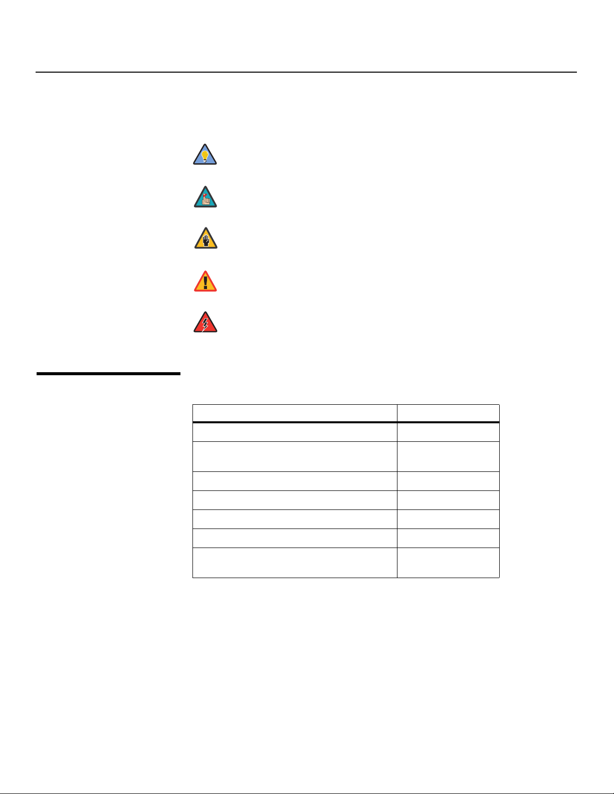
Graphic Conventions: These symbols appear in numerous places throughout the manual,
to emphasize points that you must keep in mind to avoid problems with your equipment or
injury:
TIPS highlight time-saving short cuts and helpful guidelines for using
Tip
certain features.
NOTES emphasize text with unusual importance or special significance.
They also provide supplemental information.
CAUTIONS alert users that a given action or omitted action can degrade
performance or cause a malfunction.
Y
WARNINGS appear when a given action or omitted action can result in
damage to the equipment, or possible non-fatal injury to the user.
DANGER appears when a given action can cause severe injury or death.
1.2
Using This Manual
Use the following table to locate the specific information you need in this manual.
IMINAR
Information about obtaining service iv
General information about the PlasmaView VHD
High-Definition Plasma Display
Installation instructions 15
First-time configuration instructions 33
L
PRE
Advanced configuration instructions 44
Troubleshooting tips 52
Specifications for the PlasmaView VHD
High-Definition Plasma Display
If you need... ... Turn to page:
3
61
2 Vidikron PlasmaView VHD Installation/Operation Manual

Introduction
The PlasmaView VHD High-Definition Plasma Display establishes a higher threshold for flat
panel display products. The PlasmaView VHD is available in three sizes, including our largest
and highest-resolution plasma ever, at 103 inches diagonal and 1920 x 1080 (1080p) native
resolution.
The PlasmaView VHD takes picture quality to a whole new level, boasting our brightest
picture, best contrast ratio, deepest black levels and most spot-on high definition
colorimetry ever! In addition, sophisticated 16-bit digital video processing, a new milestone,
results in 4096 steps of graduation for seamless images, completely devoid of the primitive
“solarization” and “stair stepping” characteristics previously plaguing digital flat panel
displays.
Discrete, multiple aspect ratio control includes IntelliWide™ for viewing 4:3 content in
widescreen without appreciable picture degradation, as well as ISF(ccc) calibration modes to
easily maintain ISF standards. The automation interface includes RS-232 control with discrete
aspect ratio, input and power on/off selection.
The included VHD Digital Video Controller/Processor provides a pure digital signal path from
input to output as well as a broad array of video input choices, all available from its position
in the equipment rack, with only digital video and control cables running to the display itself.
The PlasmaView VHD not only represents a leap forward in high definition flat-panel
technology, but our engineering advances in plasma design ensure that it will enjoy a long
life in any installation, with operation extending to as much as 60,000 hours. At less than
5-3/4 inches thin, the PlasmaView VHD provides unlimited installation flexibility as well.
For high-altitude installations, Vidikron also offers the VP-5000VHDa and VP-6500VHDa with
industry-leading high-altitude compliance to over 9,000 feet mean sea level (MSL). The
VP-5000VHDa and VP-6500VHDa share all other features and specifications with the
VP-5000VHD and VP-6500VHD.
IMINAR
L
Y
1.3 Description, Features and Benefits
• 16:9 Native Resolution: 1920 x 1080
• Multiple Aspect Ratios with IntelliWide™ Mode
• Includes the new VHD video controller/processor
• Less than 5-3/4 inches thin
• Models VP-5000VHDa and VP-6500VHDa are high-altitude compliant to over 9,000 feet
• Exceptional detail and artifact-free video enhancement
• Imagix™ video processing with 3:2 film detection circuitry
PRE
Key Features and BenefitsThe PlasmaView VHD offers these key features and benefits:
Vidikron PlasmaView VHD Installation/Operation Manual 3

Introduction
➤
Parts List Your PlasmaView VHD is shipped with the following items. If any items are missing or
damaged, please contact your Vidikron dealer or Vidikron Customer Service at (888)
4VIDIKRON (484-3457).
• PlasmaView VHD High-Definition Plasma Display
• AC Power Cords (2)
•Remote Control Unit and two (2), AAA-size batteries
• RJ-11 Telephone Cable, 50 feet (15.24 meters)
• Serial Port Adapter, RJ-11 Female to DB-9 Female
• Rack-mount hardware for the VHD Controller
•Cable Ties (2)
• Warranty information and registration card
• Vidikron PlasmaView VHD Installation/Operation Manual (this document)
Optional Accessories – Models VP-5000VHD and VP-5000VHDa:
• Wall Mount Kit (part number 956-0273-00)
• Table Stand (part number 956-0266-00)
Optional Accessories – Models VP-6500VHD and VP-6500VHDa:
• Wall Mount Kit (part number 956-0253-00)
• Table Stand (part number 956-0254-00)
Y
Optional Accessories – Models VP-103VHD:
• Wall Mount Kit (part number 997-5371-00)
• Floor Stand (part number 997-5269-00)
IMINAR
L
PRE
4 Vidikron PlasmaView VHD Installation/Operation Manual
indicators.
1
2
3 4
(behind
front bezel)
(behind
2
front bezel)
2Controls and Functions
2.1 PlasmaView VHD at a Glance
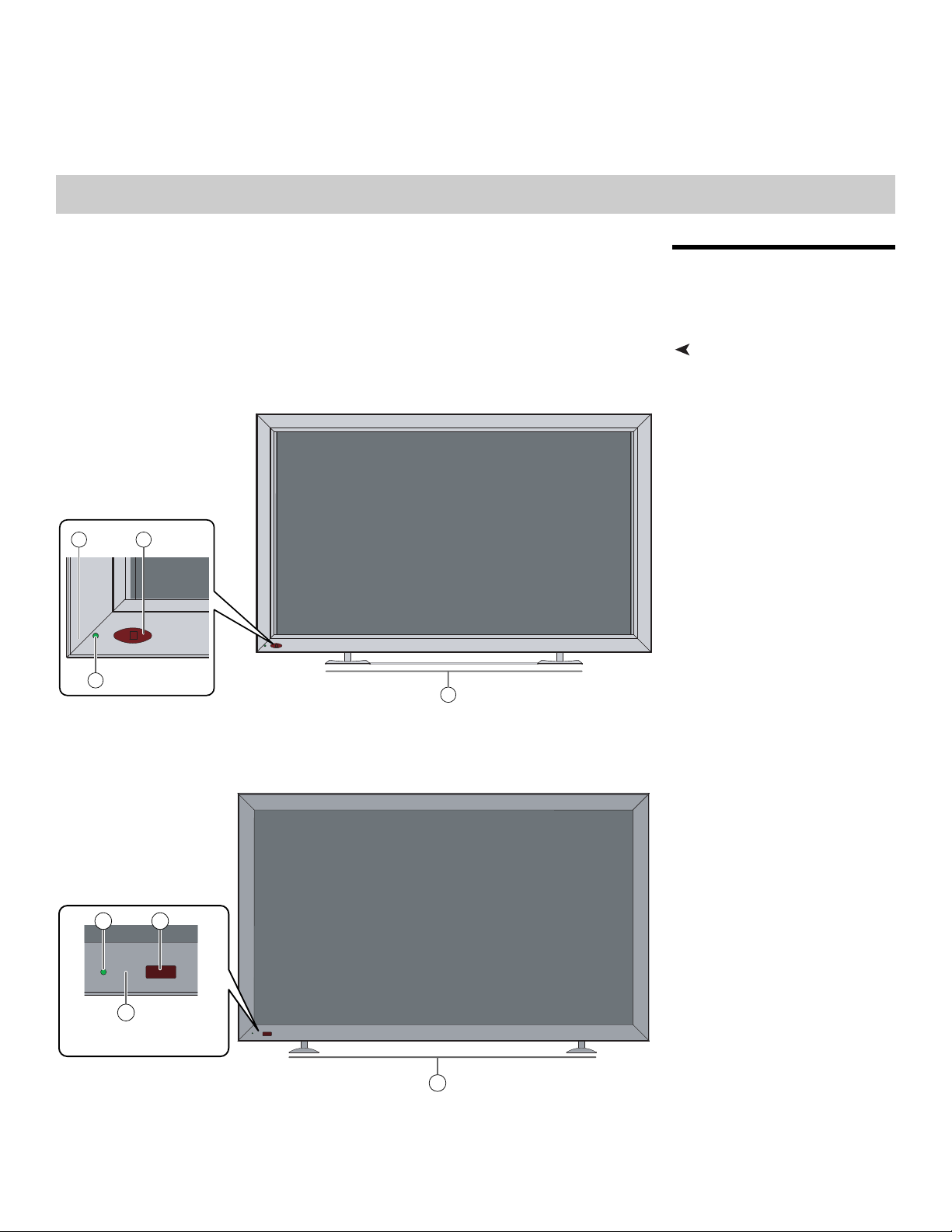
Controls and IndicatorsFigure 2-1, Figure 2-2 and Figure 2-3 show the PlasmaView VHD front-panel controls and
Y
4
IMINAR
L
3
Figure 2-1. PlasmaView VP-5000VHD Front-Panel Controls and Indicators
1
PRE
Figure 2-2. PlasmaView VP-6500VHD Front-Panel Controls and Indicators
Vidikron PlasmaView VHD Installation/Operation Manual 5
Controls and Functions
4
3
2
Y
1
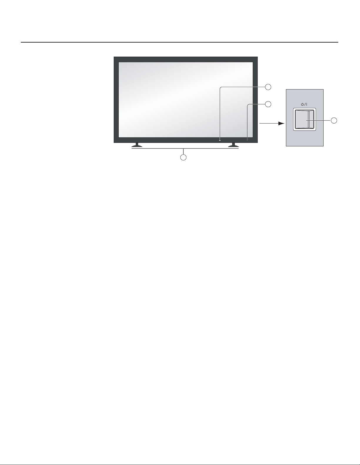
Figure 2-3. PlasmaView VP-103VHD Front-Panel Controls and Indicators
1. DISPLAY STAND
Optional accessory for table-top installations.
2. POWER BUTTON
Connects or disconnects the display panel from the AC power source.
3. STANDBY/ON INDICATOR
- Lights green to indicate normal operation;
- Lights red to indicate that the PlasmaView VHD is in standby mode.
4. REMOTE CONTROL SENSOR
Receives the signals from the remote control.
IMINAR
L
PRE
6 Vidikron PlasmaView VHD Installation/Operation Manual
Y
SERIALPC IN
AUDIO
SLOT1 SLOT2
AV IN
AB
VP-5000VHD
1 2 3 4
5
VP-6500VHD
VP-103VHD
5
5
Controls and Functions
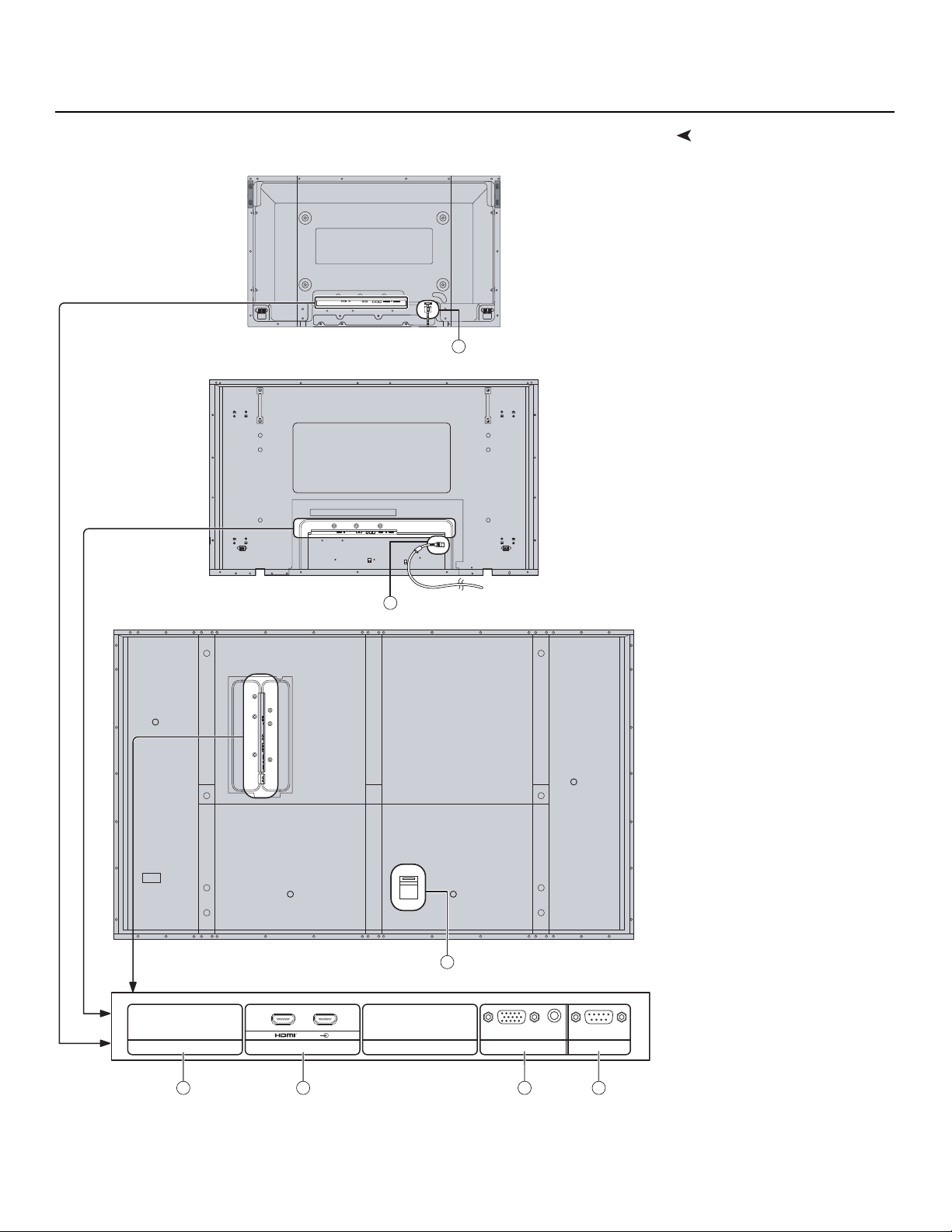
ConnectorsFigure 2-4 shows the rear-panel connector locations on the PlasmaView VHD.
IMINAR
L
PRE
Figure 2-4. PlasmaView VHD Rear Panel
Vidikron PlasmaView VHD Installation/Operation Manual 7
Controls and Functions
2.2
VHD Controller Front Panel
1. SLOT 1
Not used.
2. SLOT 2 (Dual HDMI input)
HDCP-compliant digital video inputs. Connect the HDMI output from the VHD
Controller to input “A” in this slot.
3. PC IN
Not used.
4. RS-232C (9-pin, male D-Sub)
Connect the RS-232 OUT port on the VHD Controller to this input.
5. POWER INPUT
Connect the PlasmaView VHD to AC power here.
Y
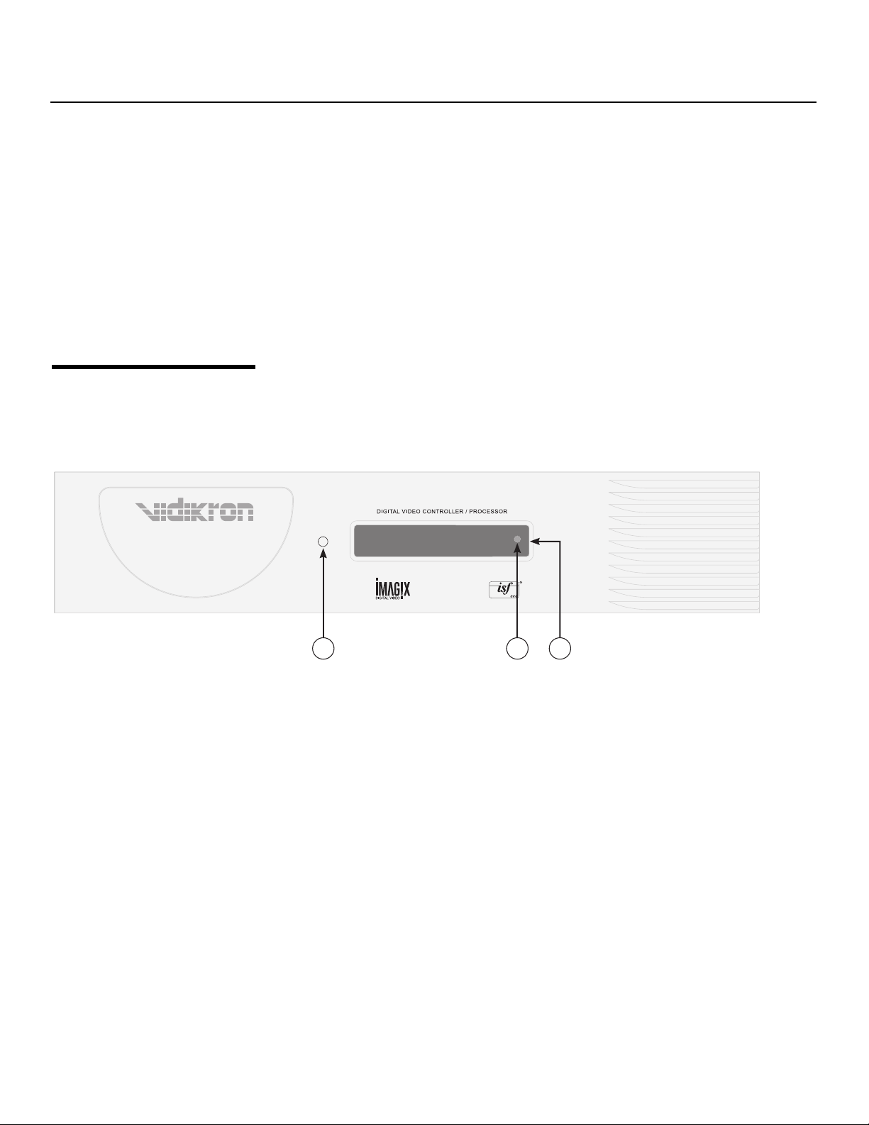
Figure 2-5 shows the controls and indicators on the VHD Controller front panel; the
paragraphs that follow describe them.
Figure 2-5. VHD Controller Front Panel
PRE
1. POWER BUTTON
2. IR SENSOR
3. VACUUM FLUORESCENT DISPLAY
Component SD NTSC 480i
16:9 VP-VHD
IMINAR
L
1 2 3
Press once to toggle from standby mode to on mode. Press it again to return to standby
mode. For a discrete on or off command, you can use the direct access buttons on the
remote control.
Receives IR commands from the remote.
Can be used instead of the On-Screen Display (OSD). Displays currently-selected menu
or – if no menu is selected – the current source, signal format (NTSC or PAL), input
resolution and aspect ratio.
8 Vidikron PlasmaView VHD Installation/Operation Manual
Controls and Functions
Tip
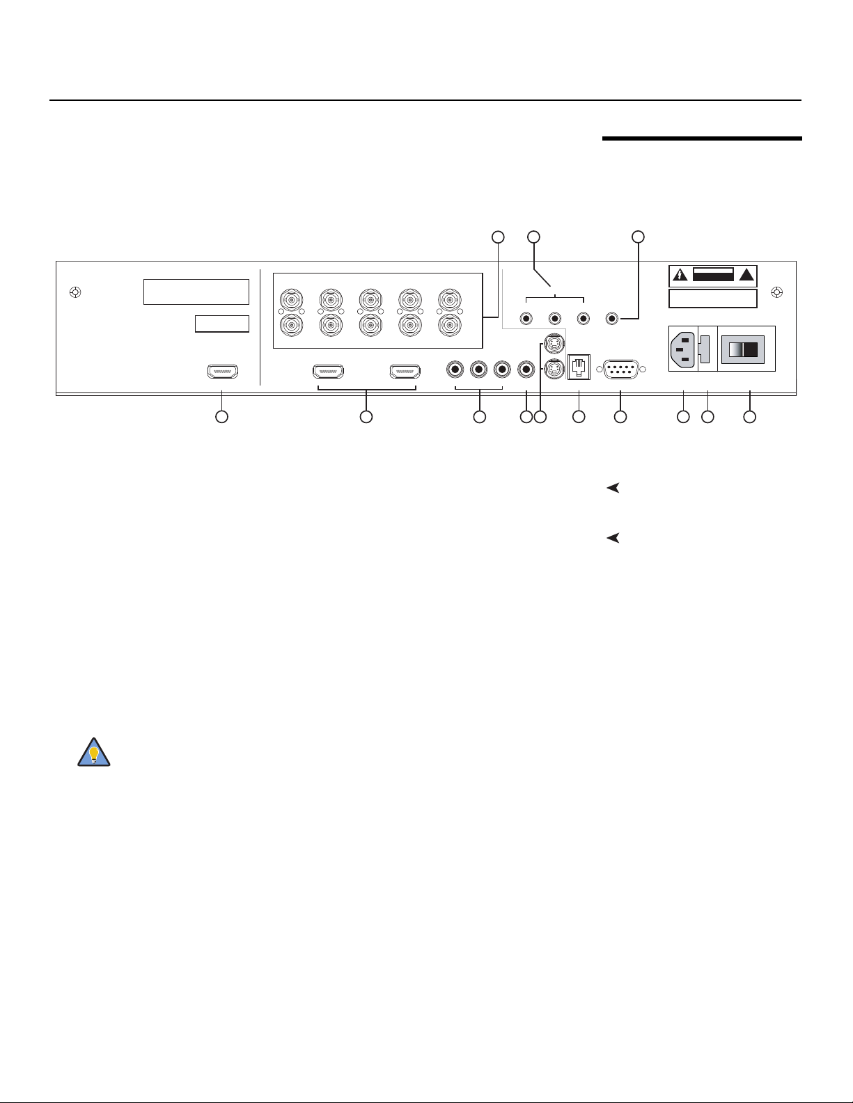
Figure 2-6 shows the rear connector panel on the VHD Controller.
3
Serial No
Model
Video Processor / Controller
1
R/Pr G/Y B/Pb
R/Pr G/Y B/Pb H V
INPUTS
HDMI 1 HDMI 2HDMI Out
2
HV
HD1
HD2
Pb Pr Y
Component Video
Video
4
Figure 2-6. VHD Controller Rear Panel
Connect this to the SLOT 2 input on the PlasmaView VHD (see Figure 2-4).
Two, HDCP-compliant digital video inputs for connecting a DVD player or HD tuner with
IMINAR
a DVI or HDMI output.
3. HD1 / HD2 (5 x Analog BNCs)
L
Two inputs (five BNCs per input) for connecting either RGB or component
high-definition television signals. The VHD Controller automatically detects the signal
format: RGB(HV) or YPrPb, 480p, 720p, 480i, 576i or 1080i.
4. COMPONENT VIDEO (RCA connectors)
Standard Definition (480i/576i) Component (YPrPb) input. This is the input for
component video from sources such as DVD players.
PRE
2.3 VHD Controller Rear Panel
79
SYSTEM CONTROL INTERFACE
TRIGGERS
2
1
S-Video 1
Y
S-Video 2
RS-232 Out
5
6
IR
3
WARNING:
TO REDUCE THE RISK OF FIRE
OR ELECTRIC SHOCK, DO NOT EXPOSE
THIS APPLIANCE TO RAIN OR MOISTURE.
RS-232 Control
10
8
Outputs1. HDMI OUT
Inputs2. HDMI 1 / HDMI 2 (Digital)
CAUTION
RISK OF ELECTRIC SHOCK
DO NOT OPEN
AVIS: RISQUE DE CHOC ELECTRIQUE-NE PAS OUVRIR
CAUTION:
TO REDUCE THE RISK OF ELECTRIC
SHOCK, DO NOT REMOVE COVER. NO USERSERVICEABLE PARTS INSIDE. REFER SERVICING
TO QUALIFIED SERVICE CENTER.
100-230VAC 50-60 Hz, 165 Watts Max
Made In USA
11
12 13
!
For best results, do not run your DVD player in progressive mode.
5. COMPOSITE VIDEO INPUT
Standard composite video input for connecting a VCR, laser disc player or other
composite video source.
6. S-VIDEO 1 / S-VIDEO 2
Two, standard S-Video inputs for connecting a DVD player, satellite receiver or Super
VHS (S-VHS) VCR.
7. 12-VOLT (750 mA) TRIGGER OUTPUTS
Connection for up to three (3), 12-volt trigger-controlled devices such as retractable
screens or screen masks.
8. ComLink (RS-232) OUTPUT
Connect this to the ComLink (RS-232) input on the projector, using the provided
communication cable.
Vidikron PlasmaView VHD Installation/Operation Manual 9

Controls and Functions
Note
9. IR
Wired input from a wired remote control or infrared receiver. It is a 3.5-mm, mini phono
jack, wired as follows:
Ring = +5V
Tip = IR Input
Sleeve = Ground
10. RS-232 CONTROL PORT
A female, 9-pin D-sub connector for interfacing with a PC or home theater
automation/control system.
11. POWER INPUT (100 to 240 VAC)
Connect the VHD Controller to power here.
12. MAIN AC FUSE
This is the main AC input fuse (5mm x 20mm, 500 mA, 250V slow-blow).
13. MAIN POWER SWITCH
Disconnects or applies power to the VHD Controller.
When an external remote control or infrared receiver is connected to the
wired IR input, the IR sensor on the front of the VHD Controller is disabled.
Y
IMINAR
L
PRE
10 Vidikron PlasmaView VHD Installation/Operation Manual
Controls and Functions
1
2
7
10
14
19
22
16
11
4
3
5
6
8
12
17
18
20
21
13
9
15
(“CUST 2” on
some models)
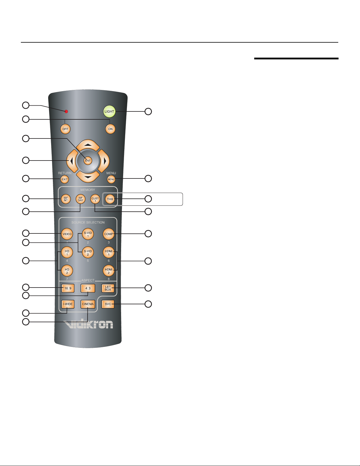
Figure 2-7 shows the VHD Controller remote control, and the paragraphs that follow describe
its functionality.
2.4 VHD Controller Remote Control
Y
IMINAR
L
Figure 2-7. VHD Controller Remote Control
Vidikron PlasmaView VHD Installation/Operation Manual 11
PRE

Controls and Functions
Note
Note
1. IR OUTPUT INDICATOR
Lights when a button is pressed to indicate that an IR signal is being transmitted.
2. LIGHT
Press to illuminate the buttons.
3. ON / OFF
Press to turn the projector on or off.
4. ENT (Enter)
Press to select a highlighted menu item or confirm a changed setting.
On some remote control units, this button is where the RETURN/EXIT
button (item #6) appears here.
Y
5. Cursor Buttons ( , , , )
Use these buttons to select items or settings, adjust settings or switch display patterns.
When no menu is present on-screen, the UP and DOWN buttons toggle through the
available aspect ratios, in this order:
UP Button = 16:9 - 4:3 - Letterbox - IntelliWide - Cinema
DOWN Button = Cinema - IntelliWide - Letterbox - 4:3 - 16:9
Likewise, the LEFT and RIGHT buttons toggle through the different source inputs, in this
order:
LEFT Button = HDMI 2 - HDMI 1 - HD/RGB2 - HD/RGB 1 - Component SD - S-Video 2 S-Video 1 - Composite
RIGHT Button = Composite - S-Video 1 - S-Video 2 - Component SD - HD/RGB 1 - HD/RGB
2 - HDMI 1 - HDMI 2
6. RETURN/EXIT
Press this button to exit the current menu and return to the previous one, or to cancel an
operation.
IMINAR
L
PRE
7. MENU
Press this button to access the OSD controls.
On some remote control units, the ENT (Enter) button (item #4) is in this
location.
12 Vidikron PlasmaView VHD Installation/Operation Manual

Memory Preset Buttons:
8. ISF NT (Night)
Press to recall settings for the current input from the “ISF Night” memory preset.
9. ISF DAY
Press to recall settings for the current input from the “ISF Day” memory preset.
10. THX (VP-6500VHD) / CUST 2 (all other models)
Press to recall settings for the current input from the “Custom 2” or “THX” memory
preset.
11. CUST 1
Press to recall settings for the current input from the “Custom 1” memory preset.
12. VIDEO (1)
Press to select Composite video input as the source or to enter the numeric character “1.”
13. S-VID 1 (2) / S-VID 2 (5) (S-Video)
Press to select an S-Video input or to enter the numeric character “2” or “5.”
14. COMP (Component) (3)
Press to select Component SD (480i/576i) video input as the source or to enter the
numeric character “3.”
Controls and Functions
Y
15. HD 1 (4) / HD 2 (7)
Press to select a HD (RGBHV or YPbPr component) input or to enter the numeric
character “4” or “7.”
16. HDMI 1 (6) / HDMI 2 (8)
Press to select a Digital Video input or to enter the numeric character “6” or “8.”
Aspect Ratio Selection Buttons:
Use these buttons to select an aspect ratio directly or to enter numeric characters, as follows:
17. 16:9 (9)
For viewing 16:9 DVDs or HDTV programs in their native aspect ratio.
18. 4:3 (0)
Scales the input signal to fit 4:3 display mode in the center of the screen.
19. LETBOX (Letterbox)
For viewing LaserDisc movies or non-anamorphic DVDs on a 16:9 screen.
20. I-WIDE (IntelliWide)
Enlarges a 4:3 image horizontally in a NON-linear fashion to fit 16:9 full screen display.
21. CINEMA
For viewing 2.35:1 source material.
22. SVC
Not used.
PRE
IMINAR
L
Vidikron PlasmaView VHD Installation/Operation Manual 13
 Loading...