

Vidikron VP-5000, VP-6000a, VP-4200a, VP-5000a, VP-6000 User Manual
...
OWNER’S OPERATING MANUAL
HIGH DEFINITION PLASMA DISPLAYS
Models VP-4200, VP-4200a, VP-5000,
VP-5000a, VP-6000 and VP-6000a
VERSION 1.0


THREE YEAR LIMITED WARRANTY
For Plasma Displays
Congratulations on your purchase of a Vidikron video product and welcome to the Vidikron family! With proper installation, setup
and care, you should enjoy many years of unparalleled video performance.
This is a LIMITED WARRANTY as defined in the Magnuson-Moss Warranty Act. Please read it carefully and retain it with your other
important documents.
WHAT IS COVERED UNDER THE TERMS OF THIS LIMITED WARRANTY:
SERVICE LABOR: Vidikron will pay for service labor by a Vidikron Authorized Service Center when needed as a result of a
manufacturing defect for a period of three (3) years from the effective date of delivery to the end user (excluding the plasma glass
panel).
PARTS (not including plasma glass panel): Vidikron will provide new or rebuilt replacement parts for the parts that fail due to
defects in materials or workmanship for a period of three (3) years from the effective date of delivery to the end user. Such
replacement parts are then subsequently warranted for the remaining portion (if any) of the original warranty period.
PLASMA GLASS PANEL: Vidikron will pay for service labor by a Vidikron Authorized Service Center when needed as a result of a
manufacturing defect for a period of one (1) year from the effective date of delivery to the end user. In addition, Vidikron will
provide new or rebuilt replacement parts for the parts that fail due to defects in materials or workmanship for a period of one (1)
year from the effective date of delivery to the end user. Such replacement parts are then subsequently warranted for the remaining
portion (if any) of the original warranty period.
Y
WHAT IS NOT COVERED UNDER THE TERMS OF THIS LIMITED WARRANTY:
Image burn-in on plasma display panels is specifically excluded from coverage under this Limited Warranty. Image burn-in is the
result of misuse of the product and therefore cannot be repaired under the terms of this Limited Warranty.
Normal viewing material such as television/satellite broadcasts, videotape or DVDs (not put into pause for extended periods of
time) will not cause damage to your display under normal conditions. Many DVD players are also equipped with screen savers for
this reason.
TO AVOID IMAGE RETENTION (Burn-in): Please ensure that still images are left on your plasma display panel for no more than a
few minutes. Also ensure that images displayed in the 4:3 aspect ratio mode (black or gray stripes, but no picture information is
present on the left and right edges of the screen) are used as infrequently as possible. This will prevent permanent image burns on
your plasma display panel, which can be seen permanently under certain conditions once burn-in has occurred.
The types of images to avoid include video games, still images and computer screens with stationary tool bars and icons. (This is
why computers are equipped with screen savers – to prevent still images from burning into the monitor’s phosphors after being
displayed continuously for an extended period of time).
This Limited Warranty only covers failure due to defects in materials and workmanship that occur during normal use and does not
cover normal maintenance. This Limited Warranty does not cover cabinets or any appearance items; failure resulting from
accident, misuse, abuse, neglect, mishandling, misapplication, faulty or improper installation or setup adjustments; improper
maintenance, alteration, improper use of any input signal; damage due to lightning or power line surges, spikes and brownouts;
damage that occurs during shipping or transit; or damage that is attributed to acts of God. In the case of remote control units,
damage resulting from leaking, old, damaged or improper batteries is also excluded from coverage under this Limited Warranty.
PRE
IMINAR
L
Vidikron PlasmaView Owner’s Operating Manual iii

CAUTION: THIS LIMITED WARRANTY ONLY COVERS VIDIKRON PRODUCTS PURCHASED FROM VIDIKRON AUTHORIZED DEALERS.
ALL OTHER PRODUCTS ARE SPECIFICALLY EXCLUDED FROM COVERAGE UNDER THIS WARRANTY. MOREOVER, DAMAGE
RESULTING DIRECTLY OR INDIRECTLY FROM IMPROPER INSTALLATION OR SETUP IS SPECIFICALLY EXCLUDED FROM COVERAGE
UNDER THIS LIMITED WARRANTY. IT IS IMPERATIVE THAT INSTALLATION AND SETUP WORK BE PERFORMED ONLY BY AN
AUTHORIZED VIDIKRON DEALER TO PROTECT YOUR RIGHTS UNDER THIS WARRANTY. THIS WILL ALSO ENSURE THAT YOU ENJOY
THE FINE PERFORMANCE OF WHICH YOUR VIDIKRON PRODUCT IS CAPABLE WHEN INSTALLED AND CALIBRATED BY VIDIKRON
AUTHORIZED PERSONNEL.
RIGHTS, LIMITS AND EXCLUSIONS:
Vidikron limits its obligations under any implied warranties under state laws to a period not to exceed the warranty period. There
are no express warranties. Vidikron also excludes any obligation on its part for incidental or consequential damages related to the
failure of this product to function properly. Some states do not allow limitations on how long an implied warranty lasts, and some
states do not allow the exclusion or limitation of incidental or consequential damages. So the above limitations or exclusions may
not apply to you. This warranty gives you specific legal rights, and you may also have other rights that vary from state to state.
EFFECTIVE WARRANTY DATE:
This warranty begins on the effective date of delivery to the end user. For your convenience, keep the original bill of sale as
evidence of the purchase date.
IMPORTANT – WARRANTY REGISTRATION:
Y
Please fill out and mail your warranty registration card. It is imperative that Vidikron knows how to reach you promptly if we should
discover a safety problem or product update for which you must be notified.
IMINAR
L
CONTACT A VIDIKRON AUTHORIZED SERVICE CENTER TO OBTAIN SERVICE:
Repairs made under the terms of this Limited Warranty covering your Vidikron video product will be performed at the location of
the product, during usual working hours, providing location of product is within normal operating distance from a Vidikron
Authorized Service Center. In some instances it may be necessary for the product to be returned to the Vidikron factory for repairs.
If, solely in Vidikron’s judgment, location of product to be repaired is beyond normal operating distance of the closest Vidikron
Authorized Service Center, or the repair requires the unit be returned to the Vidikron factory, it is the owner’s responsibility to
arrange for shipment of the product for repair. These arrangements must be made through the selling Vidikron Dealer. If this is not
possible, contact Vidikron directly for a Return Authorization number and shipping instructions. Vidikron will return product
transportation prepaid in the United States, unless no product defect is discovered. In that instance, shipping costs will be the
responsibility of the owner.
COPYRIGHT AND TRADEMARKS:
© Copyright 2007 Vidikron, a Runco International Company. This document contains proprietary information protected by
copyright, trademark and other intellectual property laws. All rights are reserved. No part of this manual may be reproduced by any
mechanical, electronic or other means, in any form, without prior written permission of the manufacturer.
Vidikron, Vision, DVSI, Imagix, CineWide, AutoScope, V2 Aperture Control, CSMS and IntelliWide are trademarks of Runco, LLC. All
other trademarks and registered trademarks used in this document are the property of their respective owners.
PRE
Vidikron products are manufactured under one or more of the following patents: US. Patent 6755540 and Other Patents Pending.
iv Vidikron PlasmaView Owner’s Operating Manual

ADDITIONAL INFORMATION:
To locate the name and address of the nearest Vidikron Authorized Service Center, or for additional information about this Limited
Warranty, please call or write:
VIDIKRON
Attn: Customer Service Department
2900 Faber Street
Union City, CA 94587
Ph: (510) 324-5900
Fax: (510) 324-5905
Toll Free: (888) 4VIDIKRON
VIDIKRON PRODUCT INFORMATION
RETAIN THIS INFORMATION FOR YOUR RECORDS
Y
IMINAR
_________________________________________________________ ________________________________________
L
Model Purchased Date
____________________________________________________________________________________________________________
Serial Number
____________________________________________________________________________________________________________
Vidikron Authorized Dealer Name
____________________________________________________________________________________________________________
PRE
Address
____________________________________________ __________________ ________________________
City State/Province Postal Code
____________________________________________ _______________________________________________________
Phone Fax
Vidikron PlasmaView Owner’s Operating Manual v

Safety Precautions
Thank you for your purchase of this quality Vidikron video product! It has been designed to provide you with the quality of video
that is expected in a home theater. For the best performance, please read this manual carefully as it is your guide through the
menus and operation.
WAR NING
CAUTION
RISK OFELECTRIC SHOCK
DO NOTOPEN
TO REDUCE THE RISK OF ELECTRIC SHOCK
DO NOT REMOVE COVER (OR BACK)
NO USER SERVICEABLE PARTS INSIDE.
REFER SERVICING TO QUALIFIED
CAUTION
To turn off main power, be sure to remove the plugs from power outlets. The power outlet socket should be installed as near to the
equipment as possible, and should be easily accessible.
WAR NIN G
TO PREVENT FIRE OR SHOCK HAZARDS, DO NOT EXPOSE THIS UNIT TO RAIN OR MOISTURE. ALSO DO NOT USE THIS UNIT’S
POLARIZED PLUG WITH AN EXTENSION CORD RECEPTACLE OR OTHER OUTLETS, UNLESS THE PRONGS CAN BE FULLY INSERTED.
REFRAIN FROM OPENING THE CABINET AS THERE ARE HIGH-VOLTAGE COMPONENTS INSIDE. REFER SERVICING TO QUALIFIED
SERVICE PERSONNEL.
WAR NIN G
CAUTION:
SERVICE PERSONNEL.
This symbol is intended to alert the user to the presence of
uninsulated “dangerous voltage” within the product’s enclosure that
may be of sufficient magnitude to constitute a risk of electric shock.
This symbol is intended to alert the user to the presence of important
operating and maintenance (servicing) instructions in the literature
accompanying the appliance.
Y
IMINAR
L
This equipment has been tested and found to comply with the limits for a Class ‘B’ digital device, pursuant to Part 15 of FCC Rules.
These limits are designed to provide reasonable protection against harmful interference when the equipment is operated in a
commercial environment. This equipment generates, uses, and can radiate radio frequency energy and, if not installed and used in
accordance with the Installation Manual, may cause harmful interference to radio communications. Operation of this equipment in
a residential area may cause harmful interference, in which case the user will be required to correct the interference at his own
expense.
DOC Compliance Notice
This Class B digital apparatus meets all requirements of the Canadian Interference-Causing Equipment Regulations.
Please read and follow the safety precautions listed below to ensure the equipment is free from damage, and to ensure that no
injury will occur as a result of improper use.
• Do not insert any object, especially metal or liquids, into the plasma display.
• Do not place any objects containing water or any other liquid on top of the plasma display.
• Do not place the units in direct sunlight, near heaters or in extremely dusty or humid locations.
• Do not install this system outdoors or otherwise exposed to the elements.
• Do not place heavy objects on top of the plasma display.
• If the power cord is damaged or frayed in any way, electrical shock and/or fire may result. Do not place objects on the power
cord, and keep the cord away from heat-emitting devices. Should the power cord become damaged in any way, please contact
your Vidikron Dealer for a replacement cord.
• Do not remove the cover of the plasma display for any reason. If any problems arise with the unit, please contact a Vidikron
Dealer or Vidikron for service. Removing the covers will void the warranty.
PRE
vi Vidikron PlasmaView Owner’s Operating Manual

1Table of Contents
THREE YEAR LIMITED WARRANTY .......................................................................................... iii
Safety Precautions ................................................................................................................... vi
1. Introduction ........................................................................................................................ 1
About This Manual ............................................................................................................................................ 1
Target Audience......................................................................................................................................... 1
If You Have Comments About This Manual... .................................................................................. 1
Textual and Graphic Conventions ....................................................................................................... 1
Using This Manual ............................................................................................................................................. 2
Description, Features and Benefits ............................................................................................................. 3
Key Features and Benefits....................................................................................................................... 3
Parts List ....................................................................................................................................................... 4
2. Controls and Functions ...................................................................................................... 5
PlasmaView at a Glance .................................................................................................................................. 5
Controls and Indicators ........................................................................................................................... 5
Connectors ................................................................................................................................................... 7
IMINAR
Y
PlasmaView Remote Control ....................................................................................................................... 10
3. Installation ........................................................................................................................ 13
Remote Control ................................................................................................................................................ 13
PRE
Quick Setup ....................................................................................................................................................... 15
Installation Considerations ..........................................................................................................................16
Connections to the PlasmaView ................................................................................................................19
L
Notes on Batteries ................................................................................................................................... 13
Notes on Remote Control Operation................................................................................................ 13
High-Altitude Operation .......................................................................................................................16
Mounting the PlasmaView on a Wall or Table Stand.................................................................. 16
Ambient Light ........................................................................................................................................... 17
Ventilation .................................................................................................................................................. 17
Other Considerations ............................................................................................................................. 18
Video Connections .................................................................................................................................. 19
Audio Connections..................................................................................................................................23
RS-232 Controller Connection ............................................................................................................ 25
Vidikron PlasmaView Owner’s Operating Manual vii

Table of Contents
4. Operation .......................................................................................................................... 27
Turning on the Power ....................................................................................................................................27
Changing the OSD Language ..................................................................................................................... 27
Selecting an Input Source ............................................................................................................................28
Viewing Input Signal Information .............................................................................................................28
Setting the Computer Display Properties ............................................................................................... 28
Changing the Aspect Ratio ..........................................................................................................................29
Using the On-Screen Menus ........................................................................................................................32
Main Menu .................................................................................................................................................34
Picture ..........................................................................................................................................................34
Screen .......................................................................................................................................................... 38
Set-Up ..........................................................................................................................................................39
Option..........................................................................................................................................................41
Option (Installer Adjust Mode) ........................................................................................................... 43
Using Picture-In-Picture (PIP) ...................................................................................................................... 47
Selecting a PIP Source ............................................................................................................................48
Swapping the Main and PIP Windows .............................................................................................48
Changing the PIP Position ....................................................................................................................48
Enlarging One Part of the Screen ..............................................................................................................49
5. Maintenance and Troubleshooting ................................................................................ 51
Cleaning .............................................................................................................................................................. 51
Cleaning the Display Panel Body and Remote Control.............................................................. 51
Cleaning the Screen ................................................................................................................................ 51
Cleaning the Vents ..................................................................................................................................51
PRE
Troubleshooting Tips .....................................................................................................................................51
6. Serial Communications ....................................................................................................53
IMINAR
L
Y
RS-232 Connection and Port Configuration ..........................................................................................53
Serial Command Syntax ................................................................................................................................53
Example....................................................................................................................................................... 53
7. Specifications .................................................................................................................... 65
PlasmaView Specifications ........................................................................................................................... 65
PlasmaView Dimensions ............................................................................................................................... 67
Computer/Video Signal Compatibility ....................................................................................................70
viii Vidikron PlasmaView Owner’s Operating Manual

1List of Figures
2-1. PlasmaView Controls and Indicators . . . . . . . . . . . . . . . . . . . . . . . . . . . . . . . . . . . . . . . . . . . . . . . . . . . . . 5
2-2. PlasmaView Model VP-4200 Connector Panel . . . . . . . . . . . . . . . . . . . . . . . . . . . . . . . . . . . . . . . . . . . . 7
2-3. PlasmaView Model VP-5000 Connector Panel . . . . . . . . . . . . . . . . . . . . . . . . . . . . . . . . . . . . . . . . . . . . 8
2-4. PlasmaView Model VP-6000 Connector Panel . . . . . . . . . . . . . . . . . . . . . . . . . . . . . . . . . . . . . . . . . . . . 8
2-5. PlasmaView Remote Control . . . . . . . . . . . . . . . . . . . . . . . . . . . . . . . . . . . . . . . . . . . . . . . . . . . . . . . . . . . 10
3-1. Available Range of the Remote Control . . . . . . . . . . . . . . . . . . . . . . . . . . . . . . . . . . . . . . . . . . . . . . . . . 13
3-2. Ventilation Requirements for Enclosure Mounting . . . . . . . . . . . . . . . . . . . . . . . . . . . . . . . . . . . . . . 17
3-3. RGB/Component Video (INPUT 1) Connection . . . . . . . . . . . . . . . . . . . . . . . . . . . . . . . . . . . . . . . . . . 19
3-4. ANALOG RGB OUT (INPUT 1) Connection . . . . . . . . . . . . . . . . . . . . . . . . . . . . . . . . . . . . . . . . . . . . . . . 20
3-5. DVI-D (INPUT 2) Connection. . . . . . . . . . . . . . . . . . . . . . . . . . . . . . . . . . . . . . . . . . . . . . . . . . . . . . . . . . . . 20
3-6. Composite or S-Video (INPUT 3) Connection . . . . . . . . . . . . . . . . . . . . . . . . . . . . . . . . . . . . . . . . . . . . 21
3-7. Component Video (INPUT 4) Connection . . . . . . . . . . . . . . . . . . . . . . . . . . . . . . . . . . . . . . . . . . . . . . . 22
3-8. DVI-D (INPUT 5) Connection. . . . . . . . . . . . . . . . . . . . . . . . . . . . . . . . . . . . . . . . . . . . . . . . . . . . . . . . . . . . 22
3-9. Attaching the Small Ferrite Cores to Audio Cables . . . . . . . . . . . . . . . . . . . . . . . . . . . . . . . . . . . . . . 23
3-10. Connecting Audio Inputs . . . . . . . . . . . . . . . . . . . . . . . . . . . . . . . . . . . . . . . . . . . . . . . . . . . . . . . . . . . . . 23
3-11. Audio Output Connection . . . . . . . . . . . . . . . . . . . . . . . . . . . . . . . . . . . . . . . . . . . . . . . . . . . . . . . . . . . . 24
3-12. Connecting Speakers . . . . . . . . . . . . . . . . . . . . . . . . . . . . . . . . . . . . . . . . . . . . . . . . . . . . . . . . . . . . . . . . . 24
3-13. RS-232 Control System Connection . . . . . . . . . . . . . . . . . . . . . . . . . . . . . . . . . . . . . . . . . . . . . . . . . . . 25
4-1. Attaching the Ferrite Cores to the Power Cable . . . . . . . . . . . . . . . . . . . . . . . . . . . . . . . . . . . . . . . . . 27
4-2. PlasmaView OSD Menu Structure. . . . . . . . . . . . . . . . . . . . . . . . . . . . . . . . . . . . . . . . . . . . . . . . . . . . . . . 33
PRE
4-3. Typical PLUGE Pattern for Adjusting Brightness . . . . . . . . . . . . . . . . . . . . . . . . . . . . . . . . . . . . . . . . . 34
4-4. Typical Gray Bar Pattern for Adjusting Contrast . . . . . . . . . . . . . . . . . . . . . . . . . . . . . . . . . . . . . . . . . 35
IMINAR
L
Y
4-5. Typical Color Bar Pattern for Adjusting Color Saturation and Tint . . . . . . . . . . . . . . . . . . . . . . . . 36
4-6. Typical Test Pattern for Adjusting Sharpness . . . . . . . . . . . . . . . . . . . . . . . . . . . . . . . . . . . . . . . . . . . . 37
4-7. Audio System Functional Block Diagram. . . . . . . . . . . . . . . . . . . . . . . . . . . . . . . . . . . . . . . . . . . . . . . . 41
4-8. Picture Orientation . . . . . . . . . . . . . . . . . . . . . . . . . . . . . . . . . . . . . . . . . . . . . . . . . . . . . . . . . . . . . . . . . . . . 46
4-9. Viewing an Enlarged Area of the Display. . . . . . . . . . . . . . . . . . . . . . . . . . . . . . . . . . . . . . . . . . . . . . . . 49
7-1. PlasmaView Model VP-4200 Dimensions (with Optional Table Stand) . . . . . . . . . . . . . . . . . . . . 67
7-2. PlasmaView Model VP-5000 Dimensions (with Optional Table Stand) . . . . . . . . . . . . . . . . . . . . 68
7-3. PlasmaView Model VP-6000 Dimensions (with Optional Table Stand) . . . . . . . . . . . . . . . . . . . . 69
Vidikron PlasmaView Owner’s Operating Manual ix

List of Figures
Notes:
Y
IMINAR
L
PRE
x Vidikron PlasmaView Owner’s Operating Manual

1Introduction
This Owner’s Manual describes how to install, set up and operate a Vidikron PlasmaView
High-Definition Plasma Display (Model VP-4200, VP-4200a, VP-5000, VP-5000a, VP-6000 or
VP-6000a).
Throughout this manual, all six models are referred to collectively as the “PlasmaView.”
Except where noted, the features and functions described in this manual are common to all
PlasmaView models.
Y
most out of the PlasmaView.
Vidikron has made every effort to ensure that this manual is accurate as of the date it was
printed. However, because of ongoing product improvements and customer feedback, it
may require updating from time to time. You can always find the latest version of this and
other Vidikron product manuals on-line, at www.Vidikron.com.
Vidikron welcomes your comments about this manual. Send them to info@Vidikron.com.
Text Conventions: The following conventions are used in this manual, in order to clarify the
information and instructions provided:
• Remote control button identifiers are set in upper-case bold type; for example, “Press EXIT
to return to the previous menu.”
• Computer or control system input (commands you type or program into the control
system) and output (responses that appear on-screen) is shown in monospace
(fixed-width) type; for example: “To change the aspect ratio to Letterbox, send the
command 02 2A 2A 53 5A 4D 53 30 33 03.”
• All keys with functional names are initial-capped, set in bold type and enclosed in angle
brackets. These keys are the following: <Enter>, <spacebar>, <Ctrl>, <Esc>
and <Tab>.
• <Enter> indicates that you may press either the RETURN or ENTER key on your keyboard
if it has both keys.
PRE
IMINAR
L
1.1 About This Manual
Target AudienceVidikron has prepared this manual to help home theater installers and end users get the
If You Have Comments About This Manual...
Textual and Graphic Conventions
In addition to these conventions, underlining, boldface and/or italics are occasionally used to
highlight important information, as in this example:
WARNING
Vidikron PlasmaView Owner’s Operating Manual 1
To prevent image retention (burn-in) on your display, ALWAYS use a
screen saver and set it to the shortest possible time.
Introduction
Graphic Conventions: These symbols appear in numerous places throughout the manual,
to emphasize points that you must keep in mind to avoid problems with your equipment or
injury:
1.2
Using This Manual
Tip
Note
Caution
TIPS highlight time-saving short cuts and helpful guidelines for using
certain features.
NOTES emphasize text with unusual importance or special significance.
They also provide supplemental information.
CAUTIONS alert users that a given action or omitted action can degrade
performance or cause a malfunction.
Y
WARNING
DANGER!
Use the following table to locate the specific information you need in this manual.
WARNINGS appear when a given action or omitted action can result in
damage to the equipment, or possible non-fatal injury to the user.
DANGER appears when a given action can cause severe injury or death.
IMINAR
If you need... ... Turn to page:
Information about obtaining service iv
L
General information about the PlasmaView High-Definition Plasma
Display
Installation instructions 13
First-time configuration instructions 27
PRE
Advanced configuration instructions 42
Troubleshooting tips 51
Specifications for the PlasmaView High-Definition Plasma Display 65
3
2 Vidikron PlasmaView Owner’s Operating Manual

Introduction
The PlasmaView High-Definition Plasma Display combines high-resolution quality and
affordability into one package. It has all of the features that one has come to expect from a
Vidikron product, including high-quality video processing, aspect ratio control and ease of
use. The advanced Vidikron processing inside the PlasmaView combined with its high native
resolution allows the most accurate scaling for all types of signals, including DVD
(progressive or interlaced), all currently-available HDTV formats and computers.
For video originally made in film, the PlasmaView has built-in 3:2 pulldown for the sharpest
and most artifact-free images possible. Like all Vidikron plasmas, it can be mounted on a wall,
ceiling or placed on a tabletop and is bright enough for use in any lighting situation: its size is
such that it can be the centerpiece of many home theaters.
The PlasmaView offers a resolution of up to 1365 x 768 and discrete aspect ratio control with
IntelliWide™ mode to fill a 16:9 screen with standard 4:3 images without loss of picture
quality. Also included are discrete source selection, multi-language support and an RS-232
interface for whole-house or automated control system integration.
The PlasmaView High-Definition Plasma Display has been carefully engineered with ISF™
calibration standards for superb video performance. At less than 5.25 inches deep, it can be
wall-mounted or used on a tabletop stand.
For high-altitude installations, Vidikron also offers the VP-4200a, VP-5000a and VP-6000a
with industry-leading high-altitude compliance to over 9000 feet (2,740 meters) mean sea
level (MSL). The VP-4200a, VP-5000a and VP-6000a share all other features and specifications
with the VP-4200, VP-5000a and VP-6000 respectively.
Y
IMINAR
• Screen Size (diagonal): 42 inches (Model VP-4200), 50 inches (Model VP-5000) or 60 inches
(Model VP-6000)
• 16:9 Native Resolution: 1024 x 768 (Model VP-4200) or 1365 x 768 (Models VP-5000 and
VP-6000)
• Multiple Aspect Ratios with IntelliWide™ Mode
• Less than 5-1/4 inches deep
• Dual DVI Inputs with High-bandwidth Digital Content Protection (HDCP)
•HDTV Compatible
• Exceptional detail and artifact-free video enhancement
• Imagix™ video processing with 3:2 film detection circuitry
PRE
L
1.3 Description, Features and Benefits
Key Features and BenefitsThe PlasmaView offers these key features and benefits:
Vidikron PlasmaView Owner’s Operating Manual 3

Introduction
Parts List Your PlasmaView is shipped with the following items. If any items are missing or damaged,
➤
please contact your Vidikron dealer or Vidikron Customer Service at (888) 4VIDIKRON.
• PlasmaView High-Definition Plasma Display
• AC Power Cord
• Remote Control Unit and two (2), AA-size batteries
•Cleaning Cloth
•Cable Ties (2)
• Ferrite Cores (2) (for AC power cord)
• Small Ferrite Cores (3) (for audio cables)
• Warranty information and registration card
• Vidikron PlasmaView Owner’s Operating Manual (this document)
• Wall Mount Kit – Vidikron part number VIHK-000300 (VP-6000) or VIHK-000200
(VP-4200/VP-5000)
– OR –
Table Stand – Vidikron part number VIHK-000325 (VP-6000), VIHK-000530 (VP-5000) or
VIHK-000225 (VP-4200)
Y
IMINAR
L
PRE
4 Vidikron PlasmaView Owner’s Operating Manual
(VP-6000)
4
(VP-4200/VP-5000)
4
2Controls and Functions
2.1 PlasmaView at a Glance
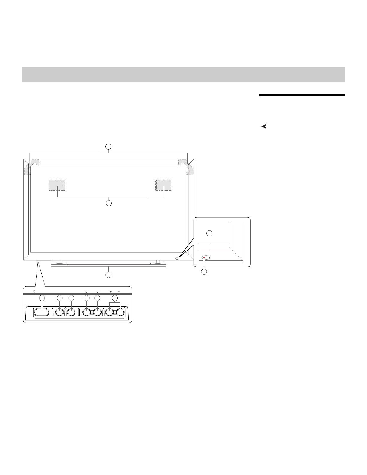
Controls and IndicatorsFigure 2-1 shows the locations of the PlasmaView controls, indicators and connectors.
Y
2
IMINAR
L
1
STANDBY/ON MENU
5 6 7 8 9 10
INFO
/ SET
PRE
Figure 2-1. PlasmaView Controls and Indicators
– VOL +INPUT ASPECT RATIO
Operation panel
on the underside
of the main unit
3
Vidikron PlasmaView Owner’s Operating Manual 5

Controls and Functions
1. DISPLAY STAND
Optional accessory for tabletop installations.
2. REMOTE CONTROL SENSOR
Receives the signals from the remote control.
3. STANDBY/ON INDICATOR
- Lights green to indicate normal operation;
- Flashes green (once per second) when the AUTO OFF feature is active.
- Lights red to indicate that the PlasmaView is in standby mode;
- Flashes green or red (twice per second) to indicate an error condition.
4. HANDLES (at the rear of the panel)
ALWAYS use the handles when carrying the unit.
5. STANDBY/ON BUTTON ( )
Press to put the display into operation or standby mode.
6. MENU
Press this button to show or hide the On-Screen Display (OSD) controls.
7. INFO/SET
When the OSD controls are visible on-screen, press this button to select an OSD
sub-menu or confirm a changed setting.
When no OSD appears on-screen, press this button to display the currently-selected
input, aspect ratio and input signal characteristics (resolution, timing etc.).
8. INPUT/UP ( )
Press this button to switch inputs or move the cursor up in the current OSD menu.
9. ASPECT RATIO/DOWN ( )
Press this button to change the aspect ratio (screen size) or move the cursor down in the
current OSD menu.
10. LEFT ( ) / VOL – and RIGHT ( ) / VOL +
These decrease or increase the volume of sound from the speakers, or move the cursor
left or right in the OSD mode.
IMINAR
L
Y
PRE
6 Vidikron PlasmaView Owner’s Operating Manual
and VP-6000 respectively.
RS-232
Controls and Functions
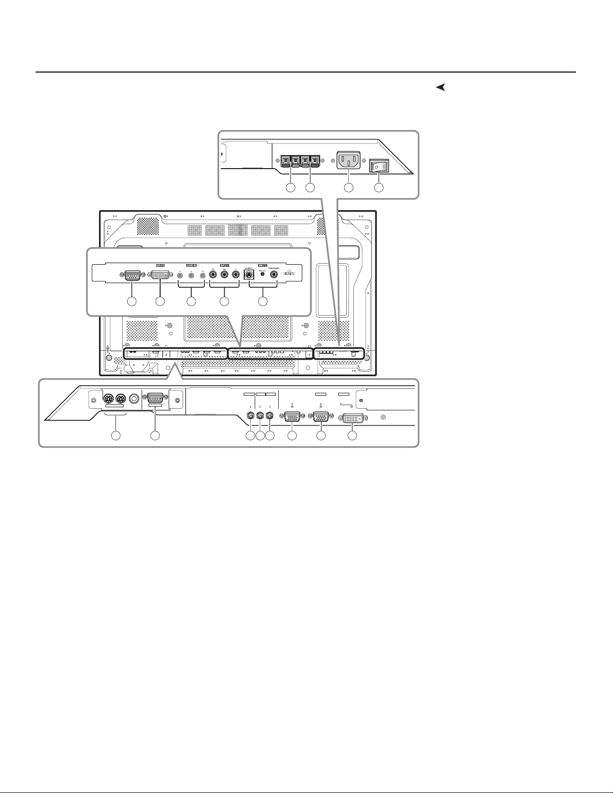
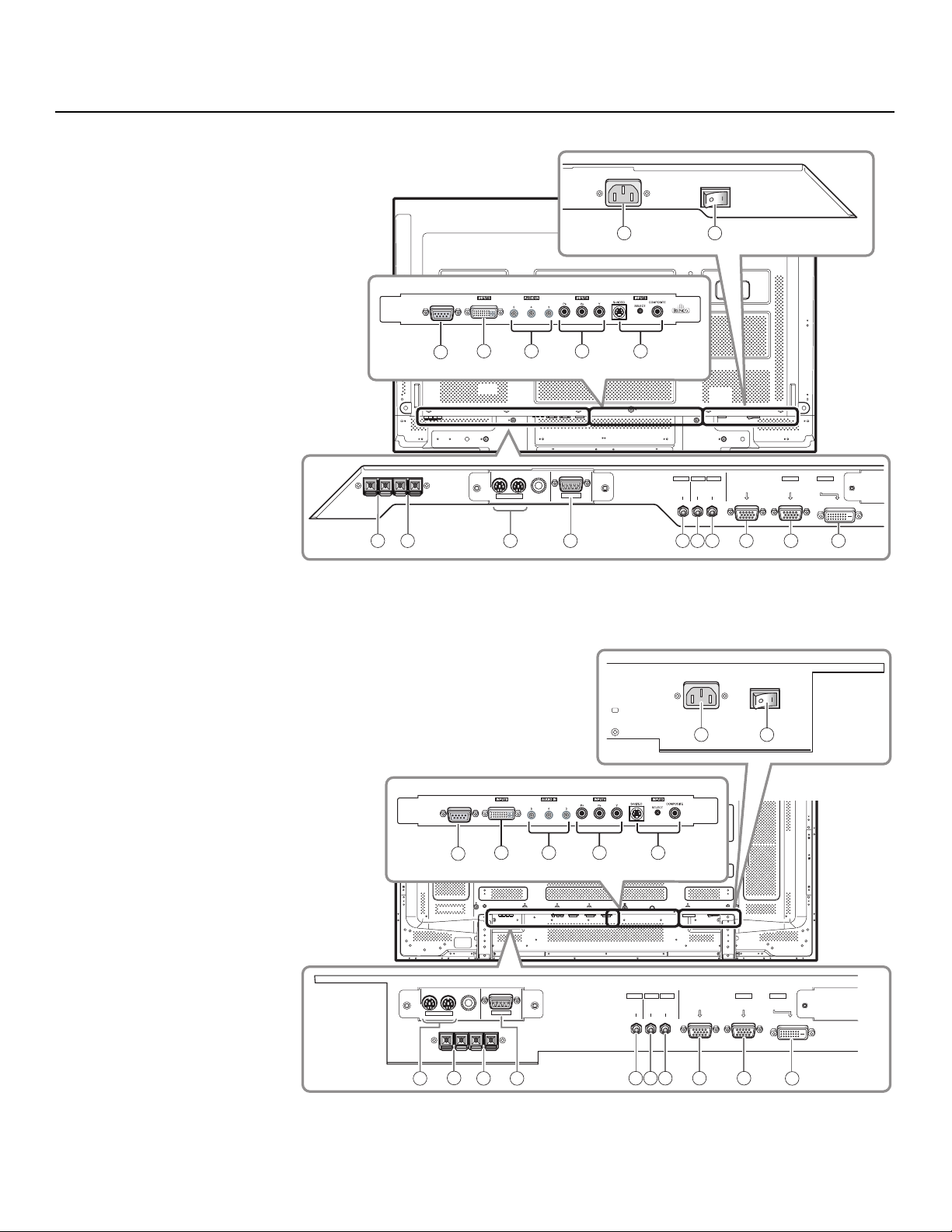
ConnectorsFigure 2-2, Figure 2-3 and Figure 2-4 show the rear-panel connector locations on the VP-4200
14 15 16 17
Y
DVI VIDEO
COMPONENT
9 10 11
IN OUT
COMBINATION
RS-232C
12 13
INPUT1
OUTPUT INPUT2
AUDIO
AUDIO AUDIO
IMINAR
L
1 2 3 4 5 6 7 8
Figure 2-2. PlasmaView Model VP-4200 Connector Panel
PRE
ANALOG RGB OUT
(D-Sub)
INPUT1
ANALOG RGB IN
(D-Sub)
INPUT2
DIGITAL RGB
(DVI-D)
Vidikron PlasmaView Owner’s Operating Manual 7
Controls and Functions
16
RS-232
DVI VIDEO
COMPONENT
10 11 12 13
9
Y
IN OUT
COMBINATION
14 15 1 2 3 4 5 6 7 8
RS-232C
Figure 2-3. PlasmaView Model VP-5000 Connector Panel
IMINAR
L
INPUT1
OUTPUT INPUT2
AUDIO
AUDIO AUDIO
17
ANALOG RGB OUT
(D-Sub)
INPUT1
ANALOG RGB IN
(D-Sub)
INPUT2
DIGITAL RGB
(DVI-D)
PRE
Figure 2-4. PlasmaView Model VP-6000 Connector Panel
1
1716
RS-232
DVI VIDEO
COMPONENT
10 11 12 13
9
IN OUT
COMBINATION
RS-232C
14
15
2
INPUT1
OUTPUT INPUT2
AUDIO
3 4 5 6 7
AUDIO AUDIO
ANALOG RGB OUT
(D-Sub)
INPUT1
ANALOG RGB IN
(D-Sub)
INPUT2
DIGITAL RGB
(DVI-D)
8
8 Vidikron PlasmaView Owner’s Operating Manual

1. COMBINATION IN/OUT
Used to control multiple PlasmaView monitors collectively. Use a 6-pin, mini-DIN cable
(all pins wired straight-through).
2. Not used.
3. AUDIO (OUTPUT) (3.5-mm stereo mini jack)
Used to output the audio of the selected source component connected to the plasma
display to an AV amplifier or similar component. The output level is fixed.
4. AUDIO (INPUT 1) (3.5-mm stereo mini jack)
Connect this jack to the audio output connector(s) of the device connected to INPUT 1.
5. AUDIO (INPUT 2) (3.5-mm stereo mini jack)
Connect this jack to the audio output connector(s) of the device connected to INPUT 2.
Controls and Functions
6. ANALOG RGB OUT (INPUT 1) (15-pin D-Sub)
If desired, connect this output to the RGB input of a second display device.
Note
7. ANALOG RGB IN (INPUT 1) (15-pin D-Sub)
For connecting components that have RGB or component output jacks such as a
personal computer or external DTV decoder (a break out cable is needed for BNC-type
connection).
8. DIGITAL RGB (INPUT 2) (DVI-D, HDCP-compliant)
VESA-standard digital video input from a personal computer, or digital video from a DVD
player or HD set-top box.
9. RS-232 (9-pin, female D-Sub)
Connect the RS-232 output from your computer or automation/control system to this
input.
10. DVI VIDEO (INPUT 5) (DVI-D, HDCP-compliant)
This DVI input will process digital video 480p, 720p and 1080i signals (computer rates are
not recommended).
11. AUDIO (INPUT 5 / INPUT 4 / INPUT 3) (3.5-mm stereo mini jack)
Used for external audio input from video sources connected to Inputs 5, 4 and 3.
12. INPUT 4
Interlaced or progressive component input (480p to 1080i, 50 or 60 Hz; 480i not
recommended – use INPUT 3 instead).
13. INPUT 3 (S-Video or Composite Video Input)
For connecting a VCR, camcorder, laser disc player or DVD player. Use the push button
between the two connectors to select S-Video or Composite Video on Input 3 (only one
can be active at a time).
This output is not active when the PlasmaView is off or in standby mode.
IMINAR
L
PRE
Y
14. EXTERNAL SPEAKER OUTPUT (RIGHT)
For connection of an external right speaker with an impedance of 6 ohms.
15. EXTERNAL SPEAKER OUTPUT (LEFT)
For connection of an external left speaker with an impedance of 6 ohms.
16. AC POWER INPUT
Connect the PlasmaView to power here, using the included power cord.
17. MAIN POWER SWITCH
Connects or disconnects the PlasmaView from the AC power source.
Vidikron PlasmaView Owner’s Operating Manual 9

Controls and Functions
2.2
PlasmaView Remote Control
Figure 2-5 shows the PlasmaView remote control. The paragraphs that follow describe its
functionality.
1
2
ASPECT
RGB
RATIO
SETUP
DVI-DRGB-HD
12
S / V COMP DVI VIDEO
345
INPUT SELECTION
POWER
INFO
10
11
Y
12
13
MENU MAGNIFY
3 14
4
IMINAR
L
5
6
7
PRE
8
9
Figure 2-5. PlasmaView Remote Control
1. ASPECT RATIO
Press this button repeatedly to select a display aspect ratio.
2. INPUT SELECT
Press one of these buttons to select an input.
MUTE VOLUME
P-OFF P-ON CLEAR
SET
PIP FUNCTION
SPLIT SUB INPUT SWAP PIP SHIFT
+
-
15
16
17
18
19
10 Vidikron PlasmaView Owner’s Operating Manual

3. MENU
Press this button to show or hide the OSD controls.
4. Directional Buttons ( / / / )
Use these buttons to navigate the OSD menus and adjust various settings.
5. SET BUTTON
Press this button to adjust or enter various settings on the unit.
6. SUB INPUT
When using the Picture-in-Picture (PIP) feature, press this button repeatedly to select a
sub-input source.
7. SPLIT
Press this button to change the PIP mode (picture-in-picture, side-by-side or off).
Controls and Functions
8. MUTE
Press this button to mute the speakers connected to the PlasmaView speaker outputs.
Press it again to restore the sound.
9. P-OFF (pin hole)
Using a straightened paper clip or similar object, press this button to program a discrete
IR code for powering off the PlasmaView into a control/automation system.
10. RGB SETUP
When using INPUT 1 to display images from a computer, press this button to
automatically set the Position, Clock and Phase settings to their optimum values.
11. STANDBY/ON ( )
Press to put the display into operation or standby mode.
12. INFO
Displays currently-selected input, aspect ratio and signal timing information.
13. INSTALLER ADJUST (pin hole)
Used to access the INSTALLER ADJUST menus.
14. MAGNIFY
Press this button to select and enlarge one part of the screen image.
15. SWAP
When using the Picture-in-Picture (PIP) feature, press this button to replace the main
screen with the sub-screen or vice versa.
16. PIP SHIFT
Press this button to change the position of the smaller PIP sub-window (lower right,
upper right, lower left or upper left).
17. VOLUME + / -
Use these buttons to increase or decrease the volume of sound from the speakers.
18. CLEAR (pin hole)
Using a straightened paper clip or similar object, press this button to clear a screen
maintenance program (refer to
PRE
Screen Maint. on page 43).
IMINAR
L
Y
19. P-ON (pin hole)
Using a straightened paper clip or similar object, press this button to program a discrete
IR code for powering on the PlasmaView into a control/automation system.
Vidikron PlasmaView Owner’s Operating Manual 11

Controls and Functions
Notes:
Y
IMINAR
L
PRE
12 Vidikron PlasmaView Owner’s Operating Manual
3Installation
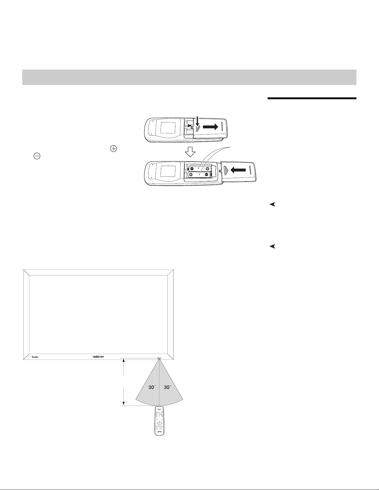
To install batteries in the remote control:
1. Remove the battery cover from the
While pressing down lightly, slide
in the direction of the arrow.
back of the remote control.
2. Insert the batteries included with the
remote control. Ensure that the
polarities correctly match the
markings inside the battery
and
Two AA (R6)
batteries
Y
compartment.
3. Replace the battery cover.
• Do not mix an old battery with a new one or different types of batteries.
• If you will not use the remote control for a long time, remove the batteries to avoid
damage from battery leakage.
The remote control can be used to control the PlasmaView within the ranges shown in Figure
IMINAR
3-1.
L
3.1 Remote Control
Notes on Batteries• When installing batteries, make sure that the battery polarities are correct.
Notes on Remote Control Operation
PRE
Approx.
23 ft (7m)
POWER
ASPECT
RGB
RATIO
SETUP
INFO
DVI-DRGB-HD
12
S / V COMP DVI VIDEO
345
INPUT SELECTION
MENU MAGNIFY
SET
PIP FUNCTION
SPLITSUB INPUT SWAP PIP SHIFT
MUTE VOLUME
+
-
P-OFF P-ONCLEAR
Figure 3-1. Available Range of the Remote Control
Vidikron PlasmaView Owner’s Operating Manual 13

Installation
• Do not drop the remote control or expose it to moisture or high temperature.
• The remote control may malfunction under a fluorescent lamp. If that occurs, move the
plasma display away from the fluorescent lamp.
• Make sure that there is nothing obstructing the infrared beam between the remote
control and the IR receiver on the plasma display.
The signal from the remote control can be reflected by walls or other
Note
• If the effective range of the remote control decreases, or it stops working, replace the
batteries with new ones.
• Ambient conditions may possibly impede the operation of the remote control. If this
happens, point the remote control at the plasma display and repeat the operation.
surfaces.
Y
IMINAR
L
PRE
14 Vidikron PlasmaView Owner’s Operating Manual

Installation
Table 3-1 gives a quick overview of the PlasmaView installation process. The sections
following this one provide detailed instructions.
Note
Table 3-1. Installation Overview
Step Procedure
Mount the PlasmaView on a wall or table stand 16
1
Connect signal sources to the PlasmaView 19
2
Connect external controller to RS-232 port (optional) 25
3
Apply power to the PlasmaView 27
4
Change the OSD language, if desired 27
5
If using the PlasmaView with a computer, adjust computer
6
display properties
Display calibration: adjust the following for each input; save
settings when finished:
• Aspect ratio
• Brightness
7
• Contrast
• Color level
• Tint
• Sharpness
Installation should be performed by a qualified custom video installation
specialist.
For Details, refer to
page...
28
IMINAR
34 through 40
L
3.2 Quick Setup
Y
PRE
Vidikron PlasmaView Owner’s Operating Manual 15

Installation
3.3 Installation Considerations
High-Altitude Operation Due to the design of all plasma glass panels made by every manufacturer, and the interaction
Mounting the PlasmaView on
a Wall or
Table Stand
Proper installation of your PlasmaView will ensure the highest possible picture quality.
Whether you are installing the PlasmaView temporarily or permanently, you should take the
following into account to ensure that it performs optimally.
➤
between ambient air pressure and the plasma gases contained inside of the panel, reliable
operation of your plasma display cannot be assured during operation at certain high-altitude
locations.
Vidikron has found this plasma monitor to operate reliably at altitudes of up to 6000 MSL
(mean sea level). At elevations higher than this, each panel may react differently, depending
upon the altitude, air pressure, humidity and other meteorological factors.
For this reason, Vidikron makes no warranties or claims as to the reliable operation of the
PlasmaView at altitudes greater than 6000 feet above sea level. If you are planning to use this
product at a location above 6000 feet, please contact Vidikron technical support for further
information.
To install the PlasmaView, you will need either an optional table stand or wall-mounting kit.
➤
The PlasmaView cannot be installed on its own.
If you do decide to wall-mount the PlasmaView, ensure that the wall-mount bracket is
installed according to the instructions included with it. The wall must be capable of
supporting a redundant weight factor three (3) times the weight of the display, or be
reinforced.
Vidikron recommends that this be done by a custom installation specialist.
IMINAR
Y
L
Note
You can attach your optional mounts or stand to the PlasmaView in either of two ways:
• While it is upright.
PRE
Use only a Vidikron-approved wall-mount kit or table stand that is
specifically designed for your display (refer to
page 4).
16 Vidikron PlasmaView Owner’s Operating Manual
 Loading...