

Vidikron VL 52 User Manual
VL-52 and VL-57
1080p HIGH-DEFINITION LCD FLAT PANEL DISPLAYS
INSTALLATION/OPERATION MANUAL


ONE YEAR LIMITED WARRANTY
For LCD Displays
Congratulations on your purchase of a Vidikron video product and welcome to the Vidikron family! With proper installation, setup
and care, you should enjoy many years of unparalleled video performance.
This is a LIMITED WARRANTY as defined in the Magnuson-Moss Warranty Act. Please read it carefully and retain it with your other
important documents.
WHAT IS COVERED UNDER THE TERMS OF THIS LIMITED WARRANTY:
SERVICE LABOR: Vidikron will pay for service labor by Vidikron Authorized Service Center when needed as a result of a
manufacturing defect for a period of one (1) year from the effective date of delivery to the end user.
Y
PARTS: Vidikron will provide new or rebuilt replacement parts for the parts that fail due to defects in materials or workmanship for
a period of one (1) year from the effective date of delivery to the end user. Such replacement parts are then subsequently
warranted for the remaining portion (if any) of the original warranty period.
WHAT IS NOT COVERED UNDER THE TERMS OF THIS LIMITED WARRANTY:
Image retention on LCD display panels is specifically excluded from coverage under this Limited Warranty. Image retention or
staining of an image is the result of misuse of the product and therefore cannot be repaired under the terms of this Limited
Warranty.
Normal viewing material such as television/satellite broadcasts, videotape or DVDs (not put into pause for extended periods of
time) will not cause damage to your display under normal conditions. Many DVD players are also equipped with screen savers for
this reason.
TO AVOID IMAGE RETENTION (Burn-in): Please ensure that still images are not left on your LCD display panel. Also ensure that
images displayed in the 4:3 aspect ratio mode (black or gray stripes, but no picture information is present on the left and right
edges of the screen) are used as infrequently as possible. This will prevent permanent retention on your LCD display panel, which
can be seen permanently under certain conditions once burn-in has occurred.
The types of images to avoid include video games, still images and computer screens with stationary tool bars and icons. (This is
why computers are equipped with screen savers – to prevent still images from burning into the monitor’s phosphors after being
displayed continuously for an extended period of time).
This Limited Warranty only covers failure due to defects in materials and workmanship that occur during normal use and does not
cover normal maintenance. This Limited Warranty does not cover cabinets or any appearance items; failure resulting from
accident, misuse, abuse, neglect, mishandling, misapplication, faulty or improper installation or setup adjustments; improper
maintenance, alteration, improper use of any input signal; damage due to lightning or power line surges, spikes and brownouts;
damage that occurs during shipping or transit; or damage that is attributed to acts of God. In the case of remote control units,
damage resulting from leaking, old, damaged or improper batteries is also excluded from coverage under this Limited Warranty.
CAUTION: THIS LIMITED WARRANTY ONLY COVERS VIDIKRON PRODUCTS PURCHASED FROM VIDIKRON AUTHORIZED DEALERS.
ALL OTHER PRODUCTS ARE SPECIFICALLY EXCLUDED FROM COVERAGE UNDER THIS LIMITED WARRANTY. MOREOVER, DAMAGE
RESULTING DIRECTLY OR INDIRECTLY FROM IMPROPER INSTALLATION OR SETUP IS SPECIFICALLY EXCLUDED FROM COVERAGE
UNDER THIS LIMITED WARRANTY. IT IS IMPERATIVE THAT INSTALLATION AND SETUP WORK BE PERFORMED ONLY BY AN
AUTHORIZED VIDIKRON DEALER TO PROTECT YOUR RIGHTS UNDER THIS WARRANTY. THIS WILL ALSO ENSURE THAT YOU ENJOY
THE FINE PERFORMANCE OF WHICH YOUR VIDIKRON PRODUCT IS CAPABLE WHEN INSTALLED AND CALIBRATED BY VIDIKRON
AUTHORIZED PERSONNEL.
PRE
IMINAR
L
Vidikron VL-52 and VL-57 Installation/Operation Manual iii

RIGHTS, LIMITS AND EXCLUSIONS:
Vidikron limits its obligations under any implied warranties under state laws to a period not to exceed the warranty period. There
are no express warranties. Vidikron also excludes any obligation on its part for incidental or consequential damages related to the
failure of this product to function properly. Some states do not allow limitations on how long an implied warranty lasts, and some
states do not allow the exclusion or limitation of incidental or consequential damages. So the above limitations or exclusions may
not apply to you. This warranty gives you specific legal rights, and you may also have other rights that vary from state to state.
EFFECTIVE WARRANTY DATE:
This warranty begins on the effective date of delivery to the end user. For your convenience, keep the original bill of sale as
evidence of the purchase date.
Y
IMPORTANT -- WARRANTY REGISTRATION:
Please fill out and mail your warranty registration card. It is imperative that Vidikron knows how to reach you promptly if we should
discover a safety problem or product update for which you must be notified.
CONTACT A VIDIKRON AUTHORIZED SERVICE CENTER TO OBTAIN SERVICE:
Repairs made under the terms of this Limited Warranty covering your Vidikron video product will be performed at the location of
the product, during usual working hours, providing location of product is within normal operating distance from a Vidikron
Authorized Service Center. In some instances it may be necessary for the product to be returned to the Vidikron factory for repairs.
If, solely in Vidikron’s judgment, location of product to be repaired is beyond normal operating distance of the closest Vidikron
Authorized Service Center, or the repair requires the unit be returned to the Vidikron factory, it is the owner’s responsibility to
arrange for shipment of the product for repair. These arrangements must be made through the selling Vidikron Dealer. If this is not
possible, contact Vidikron directly for a Return Authorization number and shipping instructions. Vidikron will return product
transportation prepaid in the United States, unless no product defect is discovered. In that instance, shipping costs will be the
responsibility of the owner.
IMINAR
L
COPYRIGHT AND TRADEMARKS:
© Copyright 2008 Vidikron, a Runco International Company. This document contains proprietary information protected by
copyright, trademark and other intellectual property laws. All rights are reserved. No part of this manual may be reproduced by any
mechanical, electronic or other means, in any form, without prior written permission of the manufacturer.
Vidikron, Vision, DVSI, Imagix, CineWide, AutoScope, V2 Aperture Control, CSMS and IntelliWide are trademarks of Runco, LLC,
licensed to Vidikron, a division of Runco International. All other trademarks and registered trademarks used in this document are
the property of their respective owners.
Vidikron products are manufactured under one or more of the following patents: US. Patent 6755540 and Other Patents Pending.
PRE
iv Vidikron VL-52 and VL-57 Installation/Operation Manual

ADDITIONAL INFORMATION:
To locate the name and address of the nearest Vidikron Authorized Service Center, or for additional information about this Limited
Warranty, please call or write:
VIDIKRON
Attn: Customer Service Department
2900 Faber Street
Union City, CA 94587
Ph: (510) 324-5900
Fax: (510) 324-5905
Toll Free: (888) 4VIDIKRON
VIDIKRON PRODUCT INFORMATION
RETAIN THIS INFORMATION FOR YOUR RECORDS
Y
IMINAR
_________________________________________________________ ________________________________________
Model Purchased Date
____________________________________________________________________________________________________________
Serial Number
____________________________________________________________________________________________________________
Vidikron Authorized Dealer Name
____________________________________________________________________________________________________________
PRE
L
Address
____________________________________________ __________________ ________________________
City State/Province Postal Code
____________________________________________ _________________________________________________________
Phone Fax
Vidikron VL-52 and VL-57 Installation/Operation Manual v
Important Safety Instructions
Thank you for your purchase of this quality Vidikron product! For best performance, please read this manual carefully as it is your
guide through the menus and operation.
WAR NING
CAUTION
RISK OFELECTRIC SHOCK
DO NOTOPEN
TO REDUCE THE RISK OF ELECTRIC SHOCK
DO NOT REMOVE COVER (OR BACK)
NO USER SERVICEABLE PARTS INSIDE.
REFER SERVICING TO QUALIFIED
1. Read these instructions.
2. Keep these instructions.
3. Heed all warnings.
4. Follow all instructions.
5. Do not use this apparatus near water.
6. Clean only with a dry cloth.
7. Do not block any of the ventilation openings. Install in accordance with the manufacturer’s instructions.
8. Do not install near any heat sources such as radiators, heat registers, stoves, or other apparatus (including amplifiers) that
produce heat.
9. Do not defeat the safety purpose of the polarized or grounding type plug. A polarized plug has two blades with one wider
than the other. A grounding type plug has two blades and a third grounding prong. The wide blade or the third prong is
provided for your safety. When the provided plug does not fit into your outlet, consult an electrician for the replacement of the
obsolete outlet.
10. Protect the power cord from being walked on or pinched particularly at plugs, convenience receptacles and the point where
they exit from the apparatus.
11. Only use the attachments/accessories specified by Vidikron.
12. Use only with a cart, stand, tripod, bracket or table specified by the manufacturer or sold with the apparatus. When
a cart is used, use caution when moving the cart/apparatus to avoid injury from tip-over.
CAUTION:
SERVICE PERSONNEL.
PRE
This symbol is intended to alert the user to the presence of
uninsulated “dangerous voltage” within the product’s enclosure that
may be of sufficient magnitude to constitute a risk of electric shock.
This symbol is intended to alert the user to the presence of important
operating and maintenance (servicing) instructions in the literature
accompanying the appliance.
Y
IMINAR
L
13. Unplug this apparatus during lightning storms or when unused for long periods of time.
14. Refer all servicing to qualified service personnel. Servicing is required when the apparatus has been damaged in
any way, such as power supply cord or plug is damaged, liquid has been spilled or objects have fallen into the apparatus, the
apparatus has been exposed to rain or moisture, does not operate normally, or has been dropped.
vi Vidikron VL-52 and VL-57 Installation/Operation Manual

Compliance Information
DECLARATION OF CONFORMITY:
Manufacturer’s Name: Vidikron, a subsidiary of Planar Systems, Inc.
Manufacturer’s Address: 2900 Faber Street, Union City, CA 94587
hereby declares that the products Model Numbers:
VL-52, VL-57
conform with the provisions of:
Council Directive 2004/108/EC on Electromagnetic Compatibility;
EN 55022 “Limits and methods of measurements of radio interference characteristics of information technology equipment” 1998;
EN 55024 “Limits and methods of measurements of immunity characteristics of information technology equipment” 1998;
Including:
• EN 61000-4-2 “Electromagnetic compatibility (EMC) Part 4: Testing and measurement techniques Section 2: Electrostatic
discharge immunity test”
• EN 61000-4-3 “Electromagnetic compatibility (EMC) Part 4: Testing and measurement techniques Section 3: Radiated,
Radio-Frequency, Electromagnetic Field Immunity Test”
• EN 61000-4-4 “Electromagnetic compatibility (EMC) Part 4: Testing and measurement techniques Section 4: Electrical fast
transient/burst immunity test”
• EN 61000-4-5 "Electromagnetic compatibility (EMC) Part 4: Testing and measurement techniques Section 5: Surge immunity
test"
• EN 61000-4-6 "Electromagnetic compatibility (EMC) Part 4: Testing and measurement techniques Section 6: Conducted
disturbances induced by radio-frequency fields immunity test"
• EN 61000-4-8 "Electromagnetic compatibility (EMC) Part 4: Testing and measurement techniques Section 8: Conducted
disturbances induced by power frequency magnetic fields immunity test"
• EN 61000-4-11 "Electromagnetic compatibility (EMC) Part 4: Testing and measurement techniques Section 11: Voltage dips,
short interruptions and voltage variations immunity tests"
PRE
IMINAR
L
Y
And:
• EN 61000-3-2 "Electromagnetic compatibility (EMC) Part 3, Section 2: Limits for harmonic current emissions (equipment input
current up to and including 16 A per phase)" 2000;
• EN 61000-3-3 "Electromagnetic compatibility (EMC) Part 3, Section 3: Limitations of voltage changes, voltage fluctuations and
flicker in public low-voltage supply systems, for equipment with rated current up to and including 16 A and not subject to
conditional connection" 1995;
Council Directive 2006/95/EC and amended by M1 and C1 on Low Voltage Equipment Safety;
EN 60950 “Safety of information technology equipment, including electrical business equipment”
The Technical Construction file required by this Directive is maintained at the corporate headquarters of Planar Systems, Inc., 1195
NW Compton Drive, Beaverton, OR 97006.
Date of Declaration: January 2008
Vidikron VL-52 and VL-57 Installation/Operation Manual vii

FCC PART 15:
NOTE: This equipment has been tested and found to comply with the limits for a Class B digital device, pursuant to Part 15 of the
FCC Rules. These limits are designed to provide reasonable protection against harmful interference in a residential installation.
This equipment generates, uses and can radiate radio frequency energy and, if not installed and used in accordance with the
instructions, may cause harmful interference to radio communications. However, there is no guarantee that interference will not
occur in a particular installation. If this equipment does cause harmful interference to radio or television reception, which can be
determined by turning the equipment off and on, the user is encouraged to try to correct the interference by one or more of the
following measures:
• Reorient or relocate the receiving antenna.
• Increase the separation between the equipment and receiver.
• Connect the equipment into an outlet on a circuit different from that to which the receiver is connected.
• Consult the dealer or an experienced radio/TV technician for help.
INDUSTRY CANADA (ICES-003):
This Class B digital apparatus complies with Canadian ICES-003.
Cet appareil numérique de la classe B est conforme à la norme NMB-003 du Canada.
IMPORTANT RECYCLE INSTRUCTIONS
Y
Lamp(s) inside this product contain mercury. This product may contain other electronic waste that can be hazardous if
not disposed of properly. Recycle or dispose in accordance with local, state, or federal Laws.
IMINAR
L
For more information, contact the Electronic Industries Alliance at WWW.EIAE.ORG.
For lamp specific disposal information check WWW.LAMPRECYCLE.ORG.
DISPOSAL OF OLD ELECTRICAL AND ELECTRONIC EQUIPMENT (Applicable throughout the European Union and other
European countries with separate collection programs)
This symbol found on your product or on its packaging, indicates that this product should not be treated as
household waste when you wish to dispose of it. Instead, it should be handed over to an applicable collection
point for the recycling of electrical and electronic equipment. By ensuring this product is disposed of correctly,
you will help prevent potential negative consequences to the environment and human health, which could
otherwise be caused by inappropriate disposal of this product. The recycling of materials will help to conserve
natural resources. This symbol is only valid in the European Union. If you wish to discard this product, please
contact your local authorities or dealer and ask for the correct method of disposal.
PRE
viii Vidikron VL-52 and VL-57 Installation/Operation Manual

1Table of Contents
ONE YEAR LIMITED WARRANTY .............................................................................................. iii
Important Safety Instructions ................................................................................................. vi
Compliance Information .........................................................................................................vii
1. Introduction ........................................................................................................................ 1
About This Manual ............................................................................................................................................ 1
Target Audience......................................................................................................................................... 1
Y
If You Have Comments About This Manual... .................................................................................. 1
Textual and Graphic Conventions ....................................................................................................... 1
Using This Manual ............................................................................................................................................. 2
Description, Features and Benefits ............................................................................................................. 3
Key Features and Benefits....................................................................................................................... 3
Parts List ........................................................................................................................................................ 3
2. Controls and Functions ...................................................................................................... 5
DView at a Glance .............................................................................................................................................. 5
Controls and Indicators ........................................................................................................................... 5
DView Inputs and Outputs ..................................................................................................................... 6
DView Remote Control .................................................................................................................................... 9
IMINAR
L
3. Installation ........................................................................................................................ 13
Remote Control ................................................................................................................................................ 13
Battery Installation ..................................................................................................................................13
PRE
Notes on Remote Control Operation................................................................................................ 13
Quick Setup ....................................................................................................................................................... 14
Installation Considerations ..........................................................................................................................15
Wall-Mounting the DView ....................................................................................................................15
Ambient Light ........................................................................................................................................... 15
Other Considerations ............................................................................................................................. 15
Connections to the DView ...........................................................................................................................15
Connecting the DView to Source Components ...........................................................................16
Monitor OUT Connection......................................................................................................................19
Connecting Headphones ...................................................................................................................... 19
Connecting External Speakers (Optional)....................................................................................... 20
Connecting to a Dolby Digital Amplifier .........................................................................................20
RS-232 Controller Connection ............................................................................................................ 21
Vidikron VL-52 and VL-57 Installation/Operation Manual ix

Table of Contents
4. Operation .......................................................................................................................... 23
Turning on the Power ....................................................................................................................................23
Changing the OSD Language ..................................................................................................................... 23
Setting the PC Display Properties ..............................................................................................................24
Using the On-Screen Menus ........................................................................................................................25
Main Menu ................................................................................................................................................27
Source ......................................................................................................................................................... 27
Aspect Ratio .............................................................................................................................................. 27
Picture Adjust ............................................................................................................................................29
Audio ........................................................................................................................................................... 33
Timer ............................................................................................................................................................ 34
Setup ............................................................................................................................................................34
ISF Calibration ..........................................................................................................................................38
Using Picture-In-Picture (PIP) ...................................................................................................................... 41
Changing the PIP Position ....................................................................................................................43
Changing the PIP Size ............................................................................................................................43
Changing the PIP Aspect Ratio ........................................................................................................... 43
Swapping the Main and PIP Images ................................................................................................. 44
Y
Swapping the Main and PIP Audio Programs ...............................................................................44
5. Maintenance and Troubleshooting ................................................................................ 45
Cleaning .............................................................................................................................................................. 45
Cleaning the Display Panel Body and Remote Control.............................................................. 45
Cleaning the Screen ................................................................................................................................ 45
Cleaning the Vents ..................................................................................................................................45
Troubleshooting Tips .....................................................................................................................................45
IMINAR
L
PRE
6. Serial Communications ....................................................................................................47
RS-232 Connection and Port Configuration ..........................................................................................47
Serial Command Syntax ................................................................................................................................47
7. Specifications .................................................................................................................... 53
DView Specifications ......................................................................................................................................53
DView Dimensions .......................................................................................................................................... 55
Computer Signal Compatibility ..................................................................................................................57
x Vidikron VL-52 and VL-57 Installation/Operation Manual

1List of Figures
2-1. DView Controls and Indicators . . . . . . . . . . . . . . . . . . . . . . . . . . . . . . . . . . . . . . . . . . . . . . . . . . . . . . . . . . 5
2-2. DView Rear-Panel Inputs and Outputs . . . . . . . . . . . . . . . . . . . . . . . . . . . . . . . . . . . . . . . . . . . . . . . . . . . 6
2-3. DView Remote Control . . . . . . . . . . . . . . . . . . . . . . . . . . . . . . . . . . . . . . . . . . . . . . . . . . . . . . . . . . . . . . . . . . 9
3-1. HDMI Connections . . . . . . . . . . . . . . . . . . . . . . . . . . . . . . . . . . . . . . . . . . . . . . . . . . . . . . . . . . . . . . . . . . . . . 16
3-2. Analog RGB Connections. . . . . . . . . . . . . . . . . . . . . . . . . . . . . . . . . . . . . . . . . . . . . . . . . . . . . . . . . . . . . . . 17
3-3. Component Video Connections . . . . . . . . . . . . . . . . . . . . . . . . . . . . . . . . . . . . . . . . . . . . . . . . . . . . . . . . 18
3-4. Composite and S-Video Connections . . . . . . . . . . . . . . . . . . . . . . . . . . . . . . . . . . . . . . . . . . . . . . . . . . . 18
3-5. AV OUT Connections. . . . . . . . . . . . . . . . . . . . . . . . . . . . . . . . . . . . . . . . . . . . . . . . . . . . . . . . . . . . . . . . . . . 19
3-6. Connecting Headphones. . . . . . . . . . . . . . . . . . . . . . . . . . . . . . . . . . . . . . . . . . . . . . . . . . . . . . . . . . . . . . . 19
3-7. External Speaker Connection. . . . . . . . . . . . . . . . . . . . . . . . . . . . . . . . . . . . . . . . . . . . . . . . . . . . . . . . . . . 20
3-8. Digital Audio Connection . . . . . . . . . . . . . . . . . . . . . . . . . . . . . . . . . . . . . . . . . . . . . . . . . . . . . . . . . . . . . . 20
3-9. RS-232 Control System Connection. . . . . . . . . . . . . . . . . . . . . . . . . . . . . . . . . . . . . . . . . . . . . . . . . . . . . 21
4-1. DView OSD Menu Structure . . . . . . . . . . . . . . . . . . . . . . . . . . . . . . . . . . . . . . . . . . . . . . . . . . . . . . . . . . . . 26
4-2. Typical PLUGE Pattern for Adjusting Brightness . . . . . . . . . . . . . . . . . . . . . . . . . . . . . . . . . . . . . . . . . 29
4-3. Typical Gray Bar Pattern for Adjusting Contrast . . . . . . . . . . . . . . . . . . . . . . . . . . . . . . . . . . . . . . . . . 30
4-4. Typical Color Bar Pattern for Adjusting Color Saturation and Tint . . . . . . . . . . . . . . . . . . . . . . . . 31
4-5. Typical Test Pattern for Adjusting Sharpness . . . . . . . . . . . . . . . . . . . . . . . . . . . . . . . . . . . . . . . . . . . . 32
4-6. DView Splash Screen. . . . . . . . . . . . . . . . . . . . . . . . . . . . . . . . . . . . . . . . . . . . . . . . . . . . . . . . . . . . . . . . . . . 40
7-1. VL-52 Dimensions . . . . . . . . . . . . . . . . . . . . . . . . . . . . . . . . . . . . . . . . . . . . . . . . . . . . . . . . . . . . . . . . . . . . . 55
7-2. VL-57 Dimensions . . . . . . . . . . . . . . . . . . . . . . . . . . . . . . . . . . . . . . . . . . . . . . . . . . . . . . . . . . . . . . . . . . . . . 56
PRE
IMINAR
L
Y
Vidikron VL-52 and VL-57 Installation/Operation Manual xi

List of Figures
Notes:
Y
IMINAR
L
PRE
xii Vidikron VL-52 and VL-57 Installation/Operation Manual

1Introduction
Note
This Owner’s Manual describes how to install, set up and operate the Vidikron DView™
VL-52/VL-57 Flat-Panel LCDs. Throughout this manual, the Vidikron DView™ VL-52/VL-57
Flat-Panel LCDs are referred to simply as the “DView.”
most out of the DView.
Vidikron has made every effort to ensure that this manual is accurate as of the date it was
printed. However, because of ongoing product improvements and customer feedback, it
may require updating from time to time. You can always find the latest version of this and
other Vidikron product manuals on-line, at www.Vidikron.com.
Vidikron welcomes your comments about this manual. Send them to info@Vidikron.com.
Text Conventions: The following conventions are used in this manual, in order to clarify the
information and instructions provided:
• Remote control button identifiers are set in upper-case bold type; for example, “Press EXIT
to return to the previous menu.”
• Computer input (commands you type) and output (responses that appear on-screen) is
shown in monospace (fixed-width) type; for example: “To change the aspect ratio to
Letterbox, type [S4E0002.”
• All keys with functional names are initial-capped, set in bold type and enclosed in angle
brackets. These keys are the following: <Enter>, <Spacebar>, <Control>, <Esc>
and <Tab>.
• <Enter> indicates that you may press either the RETURN or ENTER key on your computer
keyboard if it has both keys.
In addition to these conventions, underlining, boldface and/or italics are occasionally used to
highlight important information, as in this example:
PRE
IMINAR
L
Y
1.1 About This Manual
Target AudienceVidikron has prepared this manual to help home theater installers and end users get the
If You Have Comments About This Manual...
Textual and Graphic Conventions
A carriage return must be used after each command or string.
Vidikron VL-52 and VL-57 Installation/Operation Manual 1
Introduction
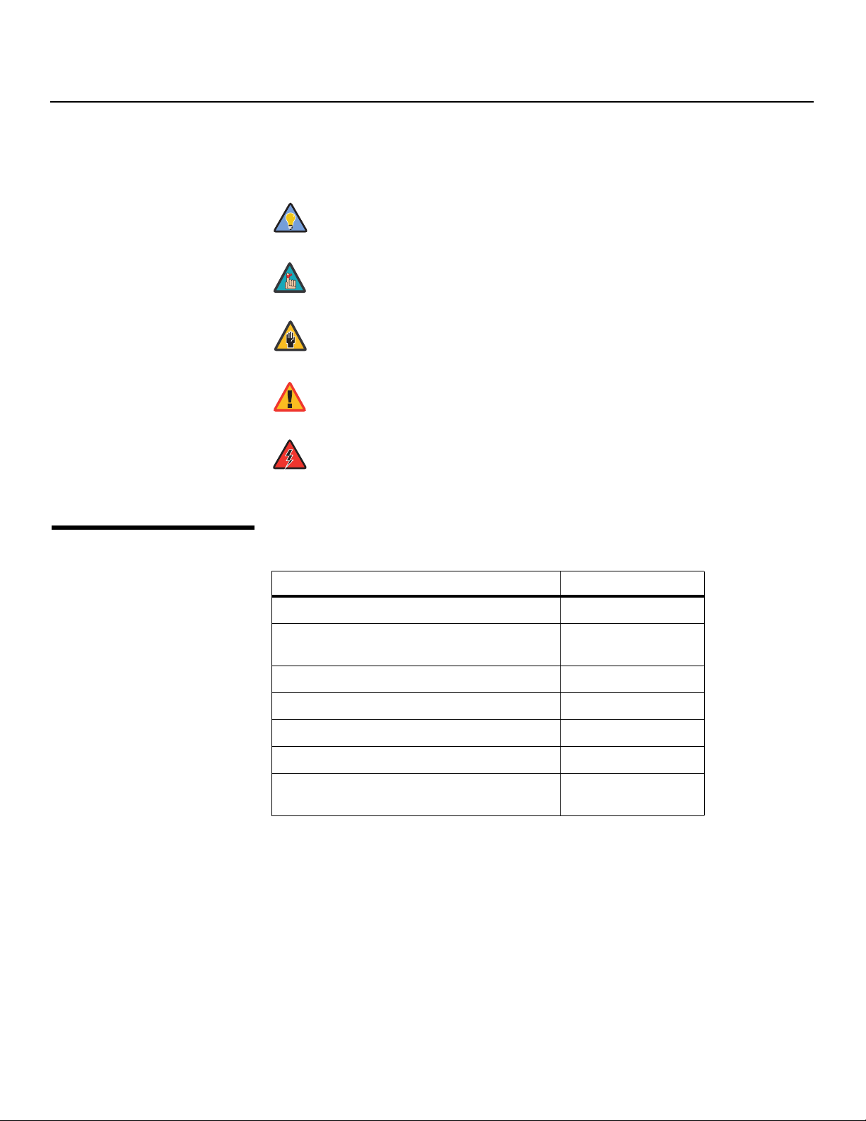
Note
Caution
WARNING
DANGER!
Graphic Conventions: These symbols appear in numerous places throughout the manual,
to emphasize points that you must keep in mind to avoid problems with your equipment or
injury:
TIPS highlight time-saving short cuts and helpful guidelines for using
Tip
certain features.
NOTES emphasize text with unusual importance or special significance.
They also provide supplemental information.
CAUTIONS alert users that a given action or omitted action can degrade
performance or cause a malfunction.
Y
WARNINGS appear when a given action or omitted action can result in
damage to the equipment, or possible non-fatal injury to the user.
DANGER appears when a given action can cause severe injury or death.
1.2
Using This Manual
Use the following table to locate the specific information you need in this manual.
IMINAR
Information about obtaining service iv
General information about the DView™
VL-52/VL-57 Flat-Panel LCDs
Installation instructions 13
First-time configuration instructions 23
L
PRE
Advanced configuration instructions 38
Troubleshooting tips 45
Specifications for the DView™ VL-52/VL-57
Flat-Panel LCDs
If you need... ... Turn to page:
3
53
2 Vidikron VL-52 and VL-57 Installation/Operation Manual

Introduction
Vidikron presents the DView™ VL-52/VL-57 Flat-Panel LCDs, perfect for those who demand
our award-winning flat panel performance along with advanced LCD technology and
lightweight design.
The DView incorporates the superb Imagix™ digital video processing that produces
outstanding picture quality with a wide range of both standard and high definition source
material. In addition, the DView includes the complete Imaging Science Foundation™ (ISF)
calibration suite to deliver the absolute best images possible under multiple viewing
conditions.
The DView offers PIP, PBP, closed captioning, Parental Control (V-Chip) functionality and
multi-language support. The display includes an integrated stereo audio system
incorporating surround sound technology and generous power amplification.
Y
The advanced, TFT active-matrix liquid crystal display panel offers 1920 x 1080 resolution
and includes Vidikron’s discrete aspect ratio control with IntelliWide™ mode to fill the 16:9
screen with standard 4:3 images without loss of picture quality. Also included are discrete
source, aspect ratio and power selection and an RS-232 interface for whole-house or
automated control system integration.
The DView is multimedia-ready, with simple computer connections making gaming, Internet
browsing and other computing activities quick and easy.
• Native Resolution: 1920 x 1080 (16:9 Native aspect ratio)
• Multiple aspect ratios with IntelliWide™ mode
• Less than 5 inches deep
• Two HDMI Inputs with High-bandwidth Digital Content Protection (HDCP)
• Exceptional detail and artifact-free video enhancement
• Vidikron video processing with 3:2 film detection circuitry
IMINAR
L
1.3 Description, Features and Benefits
Key Features and BenefitsThe DView offers these key features and benefits:
contact your Vidikron dealer or Vidikron Customer Service at (888) 4VIDIKRON.
• VL-52 or VL-57 LCD Display (with Table Stand)
• Remote Control Unit and two (2), AAA-size batteries
• AC Power Cord
• Warranty information and registration card
• Vidikron VL-52 and VL-57 Installation/Operation Manual (this document)
Optional Accessories:
• Wall Mount kit (part number 956-0262-00)
Vidikron VL-52 and VL-57 Installation/Operation Manual 3
PRE
Parts ListYour DView is shipped with the following items. If any items are missing or damaged, please

Introduction
Notes:
Y
IMINAR
L
PRE
4 Vidikron VL-52 and VL-57 Installation/Operation Manual
2Controls and Functions
2.1 DView at a Glance
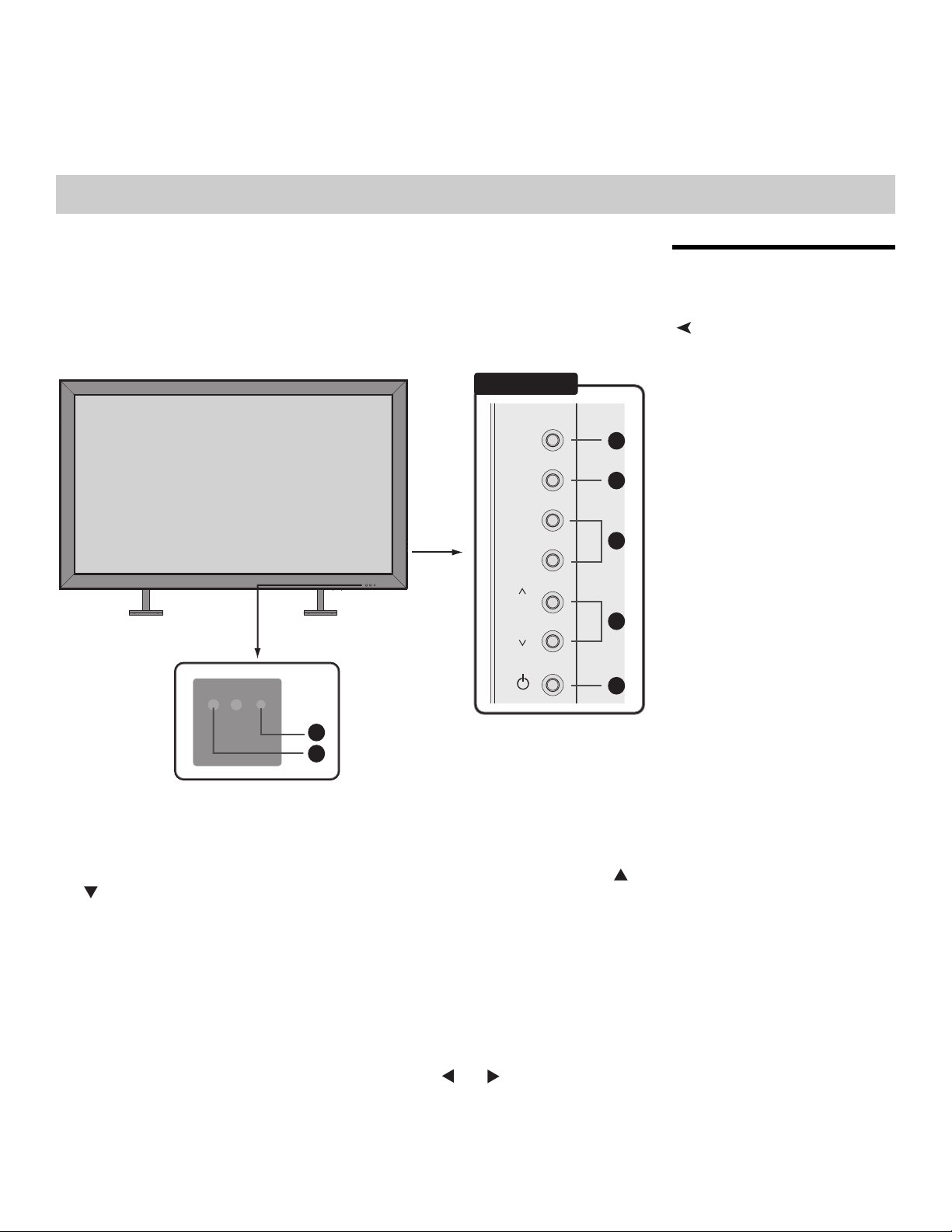
Controls and IndicatorsFigure 2-1 shows the locations of the DView controls and indicators.
7
6
PRE
Figure 2-1. DView Controls and Indicators
Right Side
AV
MENU
+
VOL
–
IMINAR
Y
1
2
3
4
L
5
1. AV Button (Input Source Selection)
To select a source, press the AV button (with no menus visible on-screen). Use the or
button (see below) to highlight the desired input source and press AV again.
When a menu is visible on-screen, this button operates identically to the ENTER button
on the DView remote control unit (refer to
2. MENU Selection Button
Press this button to access the on-screen display (OSD) controls, or to exit the current
menu and return to the previous one.
3. Volume Adjustment Buttons (VOL - / VOL +)
Use these buttons to adjust the sound volume. When a menu is visible on-screen, these
buttons operate identically to the left- and right-arrow (
remote control unit.
Vidikron VL-52 and VL-57 Installation/Operation Manual 5
DView Remote Control on page 9).
and ) buttons on the DView
Controls and Functions
➤
4. /
When a menu is visible on-screen, these buttons operate identically to the up- and
down-arrow (
5. Power Button
6. Remote Control Sensor
7. Status Indicator LED
- Lights red to indicate that the DView is in standby mode;
- Lights green during power-on sequence and during normal operation;
- Flashes green when the DView receives a signal from the remote control.
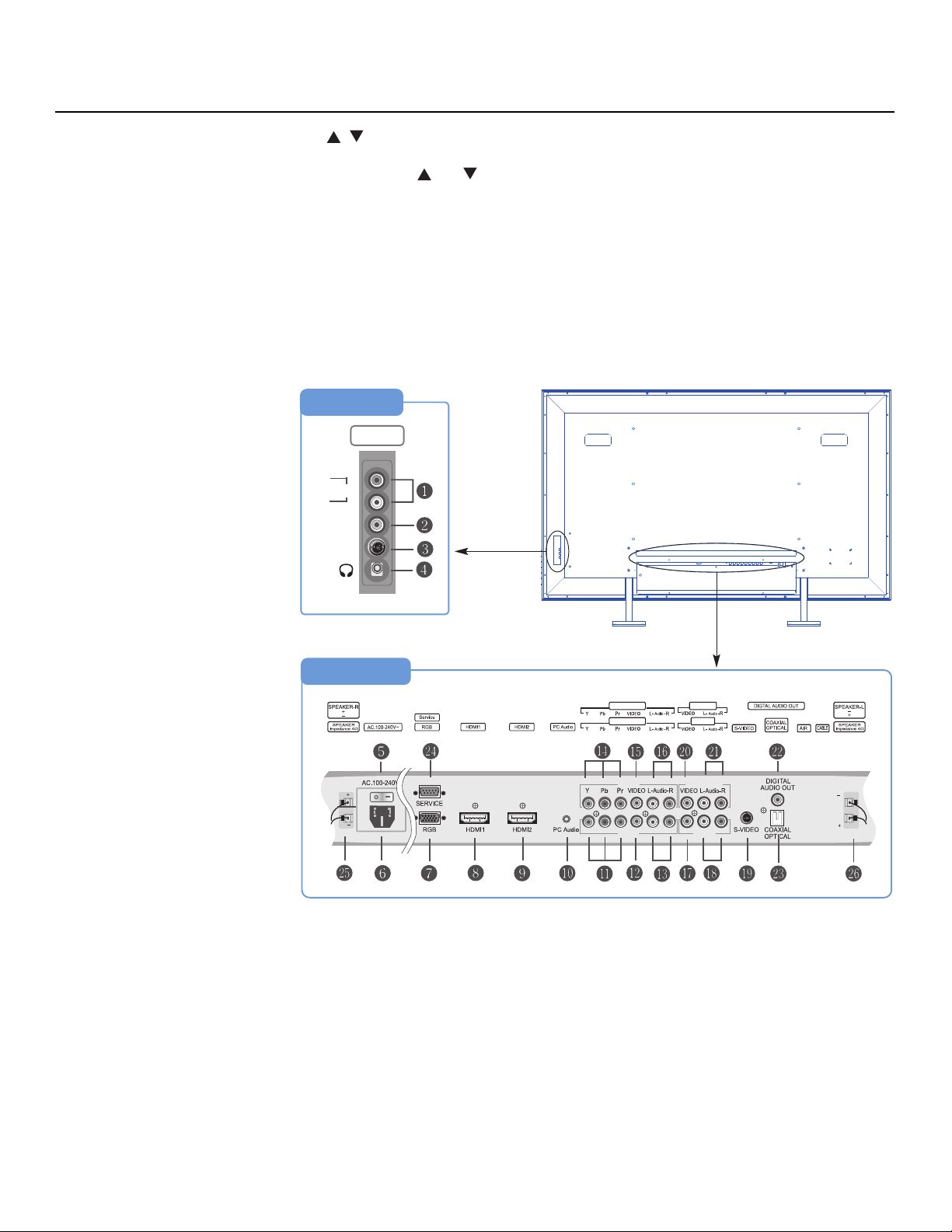
DView Inputs and Outputs Figure 2-2 shows the locations of the DView inputs and outputs.
and ) buttons on the DView remote control unit.
Right Side
INPUT2
R
Audio
L
VIDEO
S-VIDEO
IMINAR
L
Rear
PRE
Y
INPUT4
INPUT3
INPUT4
INPUT3
Monitor-Out
INPUT1
Monitor-Out
INPUT1
Figure 2-2. DView Rear-Panel Inputs and Outputs
6 Vidikron VL-52 and VL-57 Installation/Operation Manual

1. INPUT2 Audio Input
Tip
2. INPUT2 Composite Video Input
Standard composite video input for connecting a VCR, camcorder, laser disc player or
other composite video source.
3. INPUT2 S-Video Input
Standard S-Video input for connecting a DVD player, satellite receiver or Super VHS
(S-VHS) VCR.
4. Headphone Jack
5. Main Power Switch
6. Power Input (100 to 240 VAC)
Connect the DView to power here.
7. RGB
A 15-pin VGA connection to a personal computer. The DView automatically detects the
signal resolution.
8. HDMI1/Computer Input (Digital)
9. HDMI2/Computer Input (Digital)
Two, HDCP-compliant digital video inputs for connecting a DVD player, personal
computer or HD tuner with a DVI or HDMI output.
Controls and Functions
Y
For best results, do not run your DVD player in progressive mode.
IMINAR
10. PC Audio Input
Connect the audio output from a personal computer here.
11. INPUT3 Component Video (RCA connectors)
Standard-definition (480i/576i) or high-definition (720p/1080i), YPrPb component input.
This is the input for component video from sources such as DVD players.
12. INPUT3 Composite Video Input
13. INPUT3 Audio Input
Connect the audio output from your Input 3 source here.
14. INPUT4 Component Video (RCA connectors)
Standard-definition (480i/576i) or high-definition (720p/1080i), YPrPb component input.
This is the input for component video from sources such as DVD players.
15. INPUT4 Composite Video Input
16. INPUT4 Audio Input
Connect the audio output from your Input 4 source here.
17. INPUT1 Composite Video Input
18. INPUT1 Audio Input
Connect the audio output from your Input 1 source here.
19. INPUT1 S-Video Input
20. Monitor-OUT (Composite Video)
PRE
L
21. Monitor-OUT (Audio)
22. DIGITAL AUDIO OUT (S/PDIF – Coaxial)
Vidikron VL-52 and VL-57 Installation/Operation Manual 7

Controls and Functions
23. DIGITAL AUDIO OUT (TosLink – Optical)
Connect either #22 or #23 to the digital audio input of an A/V amplifier with a Dolby
®
Digital
24. RS-232 CONTROL PORT
A female, 9-pin D-sub connector for interfacing with a PC or home theater
automation/control system.
25. SPEAKER OUTPUT (RIGHT)
26. SPEAKER OUTPUT (LEFT)
For connection of the right (25) and left (26) speakers. Connect a speaker with an
impedance of 4 ohms.
decoder.
Y
IMINAR
L
PRE
8 Vidikron VL-52 and VL-57 Installation/Operation Manual
Controls and Functions
MENU
EXIT
ENTER
INPUT
1
INPUT
2
INPUT
3
INPUT
4
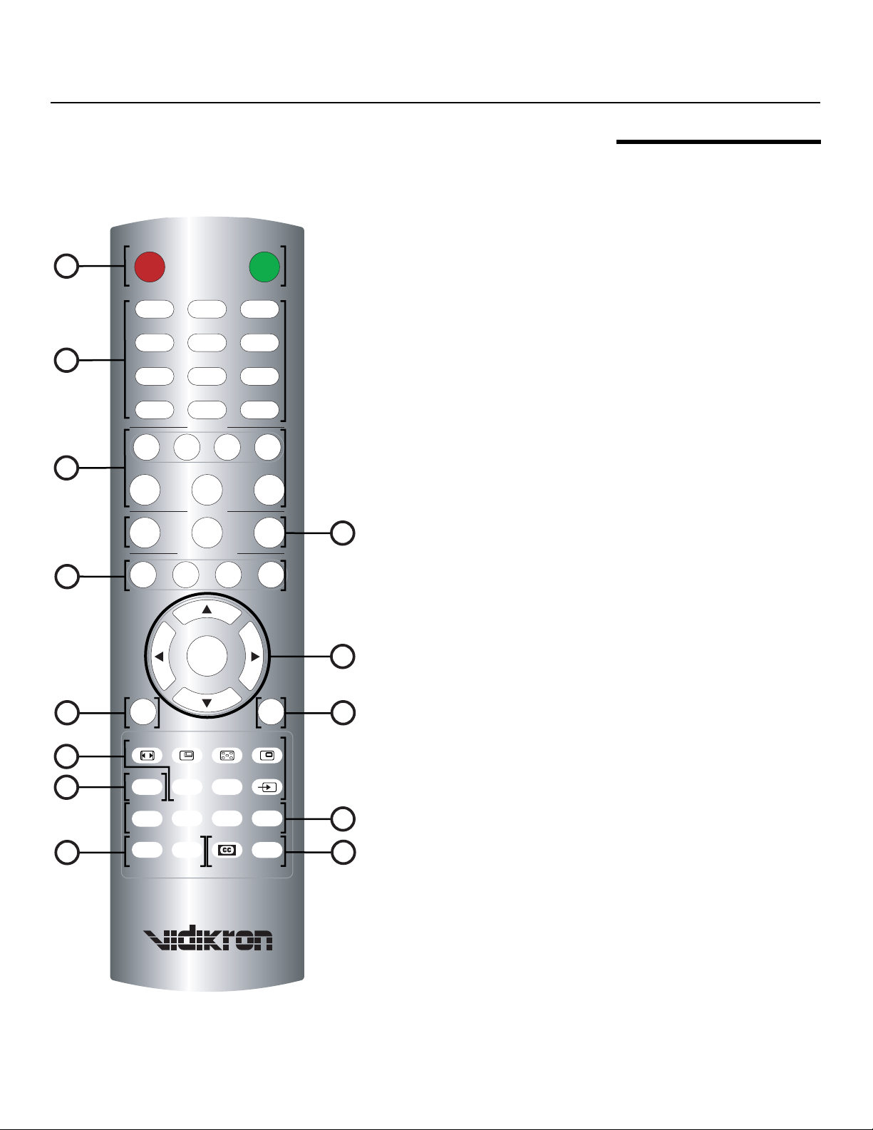
Figure 2-3 shows the DView remote control, and the paragraphs that follow describe its
functionality.
1
OFF ON
12 3
45
6
2
78 9
INPUT
0
SOURCE
INPUT
INPUT
–TV
INPUT
3
LET
BOX
RGB
HD
ISF
DAY
I-WIDE
4
IMINAR
HDMI1
CUST
5
ANA 4X3
ASPECT RATIO
HDMI2
MEMORY
ISF
NT
L
2.2 DView Remote Control
Y
VOL -
7
MENU
ASPECT SIZE POSITION PIP
ENTER
PRE
9
FAV
CHAN
SWAP TV/AVS.SWAP
MTS/SAP
10
12
TIMER
OFF
S.MODE SURRND
PREV
CHAN
Figure 2-3. DView Remote Control
EXIT
MUTE
INFO
VOL +
6
8
11
13
Vidikron VL-52 and VL-57 Installation/Operation Manual 9

Controls and Functions
Note
1. OFF / ON
Use these buttons to turn the DView on or off.
2. Numeric Buttons
Use these buttons to enter menu pass codes.
3. Source Selection Buttons
INPUT 1
Press this button to switch to Input 1.
INPUT 2
Press this button to switch to Input 2.
INPUT 3
Press this button to switch to Input 3.
INPUT 4
Press this button to switch to Input 4.
Input 1 and Input 2 have both S-Video and composite video connectors.
Input 3 and Input 4 have both component and composite video
connectors.
Y
HDMI 1 / HDMI 2
IMINAR
Use these buttons to select a Digital Video input (HDMI 1 or HDMI 2).
L
RGB HD
Press this button to switch to the RGB HD input.
4. Memory Preset Buttons
PRE
CUST
Press to recall settings for the current input from the “Custom” memory preset.
ISF NT (Night)
Press to recall settings for the current input from the “ISF Night” memory preset.
ISF DAY
Press to recall settings for the current input from the “ISF Day” memory preset.
To specify which connection type you are using – or to switch from one to
the other if equipment is connected to both – use the Input Selection menu
under Setup (refer to Input Selection on page 37).
10 Vidikron VL-52 and VL-57 Installation/Operation Manual
 Loading...