

Vidikron VL-26HD, VL-32HD User Manual
OWNER’S OPERATING MANUAL
VL-26HD and VL-32HD
HIGH DEFINITION FLAT PANEL LCD DISPLAYS
VERSION 2.3


ONE YEAR LIMITED WARRANTY
For LCD Displays
Congratulations on your purchase of a Vidikron video product and welcome to the Vidikron family! With proper installation, setup
and care, you should enjoy many years of unparalleled video performance.
This is a LIMITED WARRANTY as defined in the Magnuson-Moss Warranty Act. Please read it carefully and retain it with your other
important documents.
WHAT IS COVERED UNDER THE TERMS OF THIS LIMITED WARRANTY:
SERVICE LABOR: Vidikron will pay for service labor by a Vidikron Authorized Service Center when needed as a result of a
manufacturing defect for a period of one (1) year from the effective date of delivery to the end user.
PARTS: Vidikron will provide new or rebuilt replacement parts for the parts that fail due to defects in materials or workmanship for
a period of one (1) year from the effective date of delivery to the end user. Such replacement parts are then subsequently
warranted for the remaining portion (if any) of the original warranty period.
WHAT IS NOT COVERED UNDER THE TERMS OF THIS LIMITED WARRANTY:
Image retention on LCD display panels is specifically excluded from coverage under this Limited Warranty. Image retention or
staining of an image is the result of misuse of the product and therefore cannot be repaired under the terms of this Limited
Warranty.
Normal viewing material such as television/satellite broadcasts, videotape or DVDs (not put into pause for extended periods of
time) will not cause damage to your display under normal conditions. Many DVD players are also equipped with screen savers for
this reason.
TO AVOID IMAGE RETENTION (Burn-in): Please ensure that still images are not left on your LCD display panel. Also ensure that
images displayed in the 4:3 aspect ratio mode (black or gray stripes, but no picture information is present on the left and right
edges of the screen) are used as infrequently as possible. This will prevent permanent retention on your LCD display panel, which
can be seen permanently under certain conditions once burn-in has occurred.
The types of images to avoid include video games, still images and computer screens with stationary tool bars and icons. (This is
why computers are equipped with screen savers – to prevent still images from burning into the monitor’s phosphors after being
displayed continuously for an extended period of time).
This Limited Warranty only covers failure due to defects in materials and workmanship that occur during normal use and does not
cover normal maintenance. This Limited Warranty does not cover cabinets or any appearance items; failure resulting from
accident, misuse, abuse, neglect, mishandling, misapplication, faulty or improper installation or setup adjustments; improper
maintenance, alteration, improper use of any input signal; damage due to lightning or power line surges, spikes and brownouts;
damage that occurs during shipping or transit; or damage that is attributed to acts of God. In the case of remote control units,
damage resulting from leaking, old, damaged or improper batteries is also excluded from coverage under this Limited Warranty.
CAUTION: THIS LIMITED WARRANTY ONLY COVERS VIDIKRON PRODUCTS PURCHASED FROM VIDIKRON AUTHORIZED DEALERS.
ALL OTHER PRODUCTS ARE SPECIFICALLY EXCLUDED FROM COVERAGE UNDER THIS LIMITED WARRANTY. MOREOVER, DAMAGE
RESULTING DIRECTLY OR INDIRECTLY FROM IMPROPER INSTALLATION OR SETUP IS SPECIFICALLY EXCLUDED FROM COVERAGE
UNDER THIS LIMITED WARRANTY. IT IS IMPERATIVE THAT INSTALLATION AND SETUP WORK BE PERFORMED ONLY BY AN
AUTHORIZED VIDIKRON DEALER TO PROTECT YOUR RIGHTS UNDER THIS WARRANTY. THIS WILL ALSO ENSURE THAT YOU ENJOY
THE FINE PERFORMANCE OF WHICH YOUR VIDIKRON PRODUCT IS CAPABLE WHEN INSTALLED AND CALIBRATED BY VIDIKRON
AUTHORIZED PERSONNEL.
Vidikron VL-26/VL-32 Owner’s Operating Manual iii

RIGHTS, LIMITS AND EXCLUSIONS:
Vidikron limits its obligations under any implied warranties under state laws to a period not to exceed the warranty period. There
are no express warranties. Vidikron also excludes any obligation on its part for incidental or consequential damages related to the
failure of this product to function properly. Some states do not allow limitations on how long an implied warranty lasts, and some
states do not allow the exclusion or limitation of incidental or consequential damages. So the above limitations or exclusions may
not apply to you. This warranty gives you specific legal rights, and you may also have other rights that vary from state to state.
EFFECTIVE WARRANTY DATE:
This warranty begins on the effective date of delivery to the end user. For your convenience, keep the original bill of sale as
evidence of the purchase date.
IMPORTANT – WARRANTY REGISTRATION:
Please fill out and mail your warranty registration card. It is imperative that Vidikron knows how to reach you promptly if we should
discover a safety problem or product update for which you must be notified.
CONTACT A VIDIKRON AUTHORIZED SERVICE CENTER TO OBTAIN SERVICE:
Repairs made under the terms of this Limited Warranty covering your Vidikron video product will be performed at the location of
the product, during usual working hours, providing location of product is within normal operating distance from a Vidikron
Authorized Service Center. In some instances it may be necessary for the product to be returned to the Vidikron factory for repairs.
If, solely in Vidikron’s judgment, location of product to be repaired is beyond normal operating distance of the closest Vidikron
Authorized Service Center, or the repair requires the unit be returned to the Vidikron factory, it is the owner’s responsibility to
arrange for shipment of the product for repair. These arrangements must be made through the selling Vidikron Dealer. If this is not
possible, contact Vidikron directly for a Return Authorization number and shipping instructions. Vidikron will return product
transportation prepaid in the United States, unless no product defect is discovered. In that instance, shipping costs will be the
responsibility of the owner.
COPYRIGHT AND TRADEMARKS:
© Copyright 2007 Vidikron, a Runco International Company. This document contains proprietary information protected by
copyright, trademark and other intellectual property laws. All rights are reserved. No part of this manual may be reproduced by any
mechanical, electronic or other means, in any form, without prior written permission of the manufacturer.
Vidikron, Vision, DVSI, Imagix, CineWide, AutoScope, V2 Aperture Control, CSMS and IntelliWide are trademarks of Runco, LLC. All
other trademarks and registered trademarks used in this document are the property of their respective owners.
Vidikron products are manufactured under one or more of the following patents: US. Patent 6755540 and Other Patents Pending.
iv Vidikron VL-26/VL-32 Owner’s Operating Manual

ADDITIONAL INFORMATION:
To locate the name and address of the nearest Vidikron Authorized Service Center, or for additional information about this Limited
Warranty, please call or write:
VIDIKRON
Attn: Customer Service Department
2900 Faber Street
Union City, CA 94587
Ph: (510) 324-5900
Fax: (510) 324-5905
Toll Free: (888) 4VIDIKRON
VIDIKRON PRODUCT INFORMATION
RETAIN THIS INFORMATION FOR YOUR RECORDS
_________________________________________________________ ________________________________________
Model Purchased Date
____________________________________________________________________________________________________________
Serial Number
____________________________________________________________________________________________________________
Vidikron Authorized Dealer Name
____________________________________________________________________________________________________________
Address
____________________________________________ __________________ ________________________
City State/Province Postal Code
____________________________________________ _________________________________________________________
Phone Fax
Vidikron VL-26/VL-32 Owner’s Operating Manual v
Safety Precautions
Thank you for your purchase of this quality Vidikron product! It has been designed to provide you with the quality of video that is
expected in a home theater. For the best performance, please read this manual carefully as it is your guide through the menus and
operation.
WAR NING
CAUTION
RISK OFELECTRIC SHOCK
DO NOTOPEN
TO REDUCE THE RISK OF ELECTRIC SHOCK
DO NOT REMOVE COVER (OR BACK)
NO USER SERVICEABLE PARTS INSIDE.
REFER SERVICING TO QUALIFIED
CAUTION:
SERVICE PERSONNEL.
To turn off main power, be sure to remove the plugs from power outlets. The power outlet socket should be installed as near to the
equipment as possible, and should be easily accessible.
TO PREVENT FIRE OR SHOCK HAZARDS, DO NOT EXPOSE THIS UNIT TO RAIN OR MOISTURE. ALSO DO NOT USE THIS UNIT’S
POLARIZED PLUG WITH AN EXTENSION CORD RECEPTACLE OR OTHER OUTLETS, UNLESS THE PRONGS CAN BE FULLY INSERTED.
REFRAIN FROM OPENING THE CABINET AS THERE ARE HIGH-VOLTAGE COMPONENTS INSIDE. REFER SERVICING TO QUALIFIED
SERVICE PERSONNEL.
This symbol is intended to alert the user to the presence of
uninsulated “dangerous voltage” within the product’s enclosure that
may be of sufficient magnitude to constitute a risk of electric shock.
This symbol is intended to alert the user to the presence of important
operating and maintenance (servicing) instructions in the literature
accompanying the appliance.
CAUTION
WAR NIN G
WAR NIN G
This equipment has been tested and found to comply with the limits for a Class ‘B’ digital device, pursuant to Part 15 of FCC Rules.
These limits are designed to provide reasonable protection against harmful interference when the equipment is operated in a
commercial environment. This equipment generates, uses, and can radiate radio frequency energy and, if not installed and used in
accordance with the Installation Manual, may cause harmful interference to radio communications. Operation of this equipment in a
residential area may cause harmful interference, in which case the user will be required to correct the interference at his own expense.
DOC Compliance Notice
This Class B digital apparatus meets all requirements of the Canadian Interference-Causing Equipment Regulations.
Please read and follow the safety precautions listed below to ensure the equipment is free from damage, and to ensure that no
injury will occur as a result of improper use.
• Do not insert any object, especially metal or liquids, into the LCD display.
• Do not place any objects containing water or any other liquid on top of the LCD display.
• Do not place the units in direct sunlight, near heaters or in extremely dusty or humid locations.
• Do not install this system outdoors or otherwise exposed to the elements.
• Do not place heavy objects on top of the LCD display.
• If the power cord is damaged or frayed in any way, electrical shock and/or fire may result. Do not place objects on the power
cord, and keep the cord away from heat-emitting devices. Should the power cord become damaged in any way, please contact
your Vidikron Dealer for a replacement cord.
• Do not remove the cover of the LCD display for any reason. If any problems arise with the unit, please contact a Vidikron Dealer
or Vidikron for service. Removing the covers will void the warranty.
vi Vidikron VL-26/VL-32 Owner’s Operating Manual

1Table of Contents
ONE YEAR LIMITED WARRANTY .............................................................................................. iii
Safety Precautions ................................................................................................................... vi
1. Introduction ........................................................................................................................ 1
About This Manual ............................................................................................................................................ 1
Target Audience......................................................................................................................................... 1
If You Have Comments About This Manual... .................................................................................. 1
Textual and Graphic Conventions ....................................................................................................... 1
Using This Manual ............................................................................................................................................. 2
Description, Features and Benefits ............................................................................................................. 3
Key Features and Benefits....................................................................................................................... 3
Parts List ....................................................................................................................................................... 4
2. Controls and Functions ...................................................................................................... 5
DView at a Glance .............................................................................................................................................. 5
Controls and Indicators ........................................................................................................................... 5
Connectors .................................................................................................................................................. 6
DView Remote Control .................................................................................................................................... 8
3. Installation ........................................................................................................................ 13
Remote Control ................................................................................................................................................ 13
Battery Installation ..................................................................................................................................13
Notes on Remote Control Operation................................................................................................ 13
Quick Setup ....................................................................................................................................................... 14
Installation Considerations ..........................................................................................................................15
Wall-Mounting the DView ....................................................................................................................15
Ambient Light ........................................................................................................................................... 15
Other Considerations ............................................................................................................................. 15
Connections to the DView ...........................................................................................................................16
Rear Connector Access .......................................................................................................................... 16
Connecting the DView to Source Components ...........................................................................16
MONITOR OUT Connection ..................................................................................................................20
Connecting Headphones ...................................................................................................................... 20
RS-232 Controller Connection ............................................................................................................ 21
Vidikron VL-26/VL-32 Owner’s Operating Manual vii

4. Operation .......................................................................................................................... 23
Turning on the Power ....................................................................................................................................23
Changing the OSD Language ..................................................................................................................... 23
Setting the PC Display Properties ..............................................................................................................23
Using the On-Screen Menus ........................................................................................................................24
Main Menu ................................................................................................................................................26
Source ......................................................................................................................................................... 26
Aspect Ratio .............................................................................................................................................. 26
Picture Adjust ...........................................................................................................................................28
Audio ........................................................................................................................................................... 33
Channel ...................................................................................................................................................... 34
Timer.............................................................................................................................................................34
Setup ........................................................................................................................................................... 35
ISF Calibration ..........................................................................................................................................37
Using Picture-In-Picture (PIP) ...................................................................................................................... 40
Changing the PIP Position ....................................................................................................................41
Changing the PIP Size ............................................................................................................................42
Changing the PIP Aspect Ratio ........................................................................................................... 42
Changing the PIP Image Mode ...........................................................................................................42
Swapping the Main and PIP Images ................................................................................................. 43
Swapping the Main and PIP Audio Programs ...............................................................................43
Stereo Sound/SAP ...........................................................................................................................................44
5. Maintenance and Troubleshooting ................................................................................ 45
Cleaning .............................................................................................................................................................. 45
Cleaning the Display Panel Body and Remote Control.............................................................. 45
Cleaning the Screen ................................................................................................................................ 45
Cleaning the Vents ..................................................................................................................................45
Troubleshooting Tips .....................................................................................................................................45
6. Serial Communications ....................................................................................................47
RS-232 Connection and Port Configuration ..........................................................................................47
Serial Command Syntax ................................................................................................................................47
7. Specifications .................................................................................................................... 51
DView Specifications ......................................................................................................................................51
DView Dimensions .......................................................................................................................................... 52
Computer/Video Signal Compatibility ....................................................................................................54
viii Vidikron VL-26/VL-32 Owner’s Operating Manual

1List of Figures
2-1. DView Controls and Indicators . . . . . . . . . . . . . . . . . . . . . . . . . . . . . . . . . . . . . . . . . . . . . . . . . . . . . . . . . . 5
2-2. DView Connectors . . . . . . . . . . . . . . . . . . . . . . . . . . . . . . . . . . . . . . . . . . . . . . . . . . . . . . . . . . . . . . . . . . . . . . 6
2-3. DView Remote Control . . . . . . . . . . . . . . . . . . . . . . . . . . . . . . . . . . . . . . . . . . . . . . . . . . . . . . . . . . . . . . . . . . 8
3-1. Antenna/Cable TV Connection . . . . . . . . . . . . . . . . . . . . . . . . . . . . . . . . . . . . . . . . . . . . . . . . . . . . . . . . . 16
3-2. DVI Connections . . . . . . . . . . . . . . . . . . . . . . . . . . . . . . . . . . . . . . . . . . . . . . . . . . . . . . . . . . . . . . . . . . . . . . . 17
3-3. Analog RGB Connections. . . . . . . . . . . . . . . . . . . . . . . . . . . . . . . . . . . . . . . . . . . . . . . . . . . . . . . . . . . . . . . 18
3-4. Component Video Connections . . . . . . . . . . . . . . . . . . . . . . . . . . . . . . . . . . . . . . . . . . . . . . . . . . . . . . . . 19
3-5. Composite and S-Video Connections . . . . . . . . . . . . . . . . . . . . . . . . . . . . . . . . . . . . . . . . . . . . . . . . . . . 19
3-6. Monitor Output Connections. . . . . . . . . . . . . . . . . . . . . . . . . . . . . . . . . . . . . . . . . . . . . . . . . . . . . . . . . . . 20
3-7. Connecting Headphones. . . . . . . . . . . . . . . . . . . . . . . . . . . . . . . . . . . . . . . . . . . . . . . . . . . . . . . . . . . . . . . 20
3-8. RS-232 Control System Connection. . . . . . . . . . . . . . . . . . . . . . . . . . . . . . . . . . . . . . . . . . . . . . . . . . . . . 21
4-1. DView OSD Menu Structure . . . . . . . . . . . . . . . . . . . . . . . . . . . . . . . . . . . . . . . . . . . . . . . . . . . . . . . . . . . . 25
4-2. Typical PLUGE Pattern for Adjusting Brightness . . . . . . . . . . . . . . . . . . . . . . . . . . . . . . . . . . . . . . . . . 29
4-3. Typical Gray Bar Pattern for Adjusting Contrast . . . . . . . . . . . . . . . . . . . . . . . . . . . . . . . . . . . . . . . . . 30
4-4. Typical Color Bar Pattern for Adjusting Color Saturation and Tint . . . . . . . . . . . . . . . . . . . . . . . . 30
4-5. Typical Test Pattern for Adjusting Sharpness . . . . . . . . . . . . . . . . . . . . . . . . . . . . . . . . . . . . . . . . . . . . 32
4-6. DView Splash Screen. . . . . . . . . . . . . . . . . . . . . . . . . . . . . . . . . . . . . . . . . . . . . . . . . . . . . . . . . . . . . . . . . . . 39
7-1. VL-26 Dimensions . . . . . . . . . . . . . . . . . . . . . . . . . . . . . . . . . . . . . . . . . . . . . . . . . . . . . . . . . . . . . . . . . . . . . 52
7-2. VL-32 Dimensions . . . . . . . . . . . . . . . . . . . . . . . . . . . . . . . . . . . . . . . . . . . . . . . . . . . . . . . . . . . . . . . . . . . . . 53
Vidikron VL-26/VL-32 Owner’s Operating Manual ix

List of Figures
Notes:
x Vidikron VL-26/VL-32 Owner’s Operating Manual

1Introduction
This Owner’s Manual describes how to install, set up and operate the Vidikron VL-26 and
VL-32 LCD Displays. Throughout this manual, the Vidikron VL-26 and VL-32 LCD Displays are
referred to simply as the “DView.”
most out of the DView.
Vidikron has made every effort to ensure that this manual is accurate as of the date it was
printed. However, because of ongoing product improvements and customer feedback, it
may require updating from time to time. You can always find the latest version of this and
other Vidikron product manuals on-line, at www.vidikron.com.
Vidikron welcomes your comments about this manual. Send them to info@vidikron.com.
Text Conventions: The following conventions are used in this manual, in order to clarify the
information and instructions provided:
• Remote control button identifiers are set in upper-case bold type; for example, “Press EXIT
to return to the previous menu.”
• All keys with functional names are initial-capped, set in bold type and enclosed in angle
brackets. These keys are the following: <Enter>, <Spacebar>, <Control>, <Esc> and
<Tab>.
• <Enter> indicates that you may press either the RETURN or ENTER key on your computer
keyboard if it has both keys.
• Computer input (commands you type) and output (responses that appear on-screen) is
shown in monospace (fixed-width) type; for example: “To change the aspect ratio to
Letterbox, type [S4E0002.”
1.1 About This Manual
Target AudienceVidikron has prepared this manual to help home theater installers and end users get the
If You Have Comments About This Manual...
Textual and Graphic Conventions
In addition to these conventions, underlining, boldface and/or italics are occasionally used to
highlight important information, as in this example:
A carriage return must be used after each command or string.
Note
Vidikron VL-26/VL-32 Owner’s Operating Manual 1
Introduction
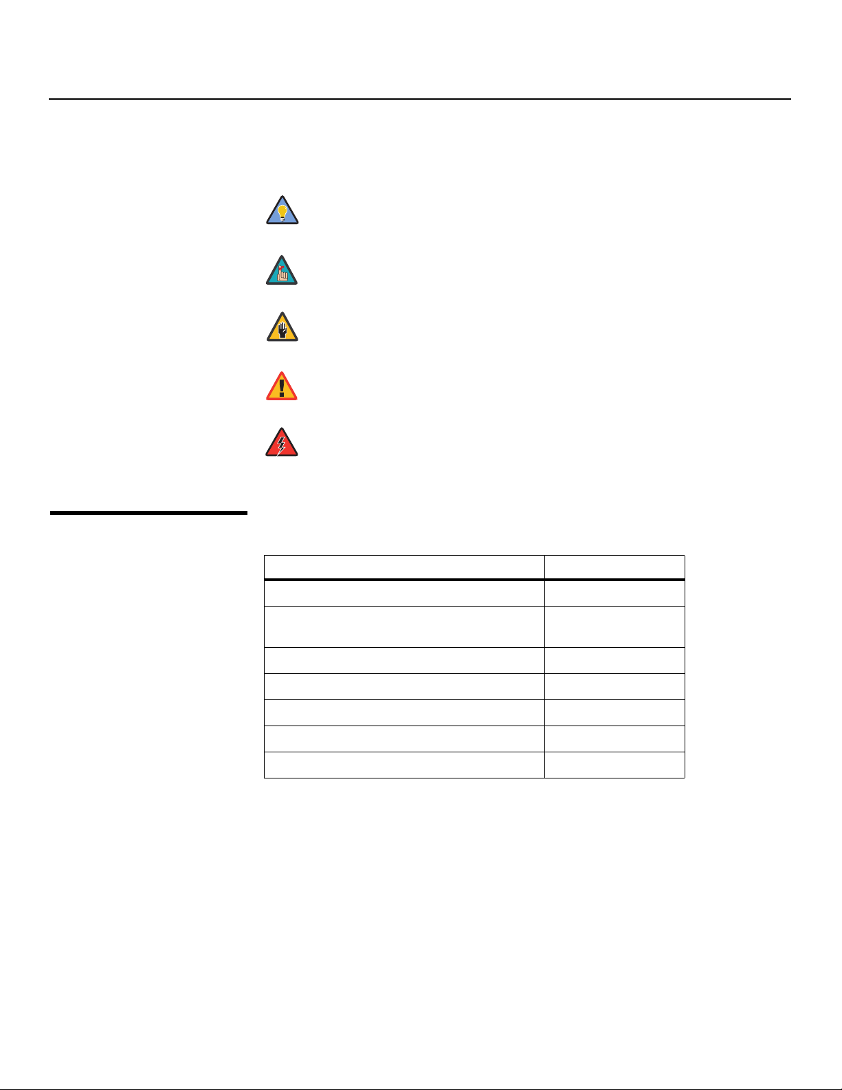
Graphic Conventions: These symbols appear in numerous places throughout the manual,
to emphasize points that you must keep in mind to avoid problems with your equipment or
injury:
1.2
Using This Manual
Tip
certain features.
NOTES emphasize text with unusual importance or special significance.
TIPS highlight time-saving short cuts and helpful guidelines for using
Note
They also provide supplemental information.
CAUTIONS alert users that a given action or omitted action can degrade
Caution
performance or cause a malfunction.
WARNINGS appear when a given action or omitted action can result in
WARNING
damage to the equipment, or possible non-fatal injury to the user.
DANGER appears when a given action can cause severe injury or death.
DANGER!
Use the following table to locate the specific information you need in this manual.
If you need... ... Turn to page:
Information about obtaining service iv
General information about the VL-26 and VL-32
LCD Displays
Installation instructions 13
First-time configuration instructions 23
Advanced configuration instructions 37
Troubleshooting tips 45
Specifications for the VL-26 and VL-32 LCD Displays 51
3
2 Vidikron VL-26/VL-32 Owner’s Operating Manual

Introduction
Vidikron presents the high performance DView™ Series VL-26 and VL-32 LCD Displays,
perfect for those who demand our award-winning flat panel performance in a more intimate
size than we offer with our larger plasma monitors. The new DView™ high definition capable
LCD displays are ideal for close-in viewing where picture quality remains a high priority, but
larger displays cannot be accommodated.
The DView™ Series VL-26 and VL-32 LCD Displays incorporate the superb Imagix™ digital
video processing that produces outstanding picture quality with a wide range of both
standard and high definition source material. In addition, the handsome, pewter-finish
television is engineered with ISF™ calibration standards for the purest video performance.
The VL-26 and VL-32 LCD Displays also feature a built-in ATSC tuner that receives terrestrial
DTV broadcasts, in addition to an advanced, 185 channel, cable-ready NTSC stereo tuner. The
DView offers PIP, PBP, closed captioning, Parental Control (V-Chip) functionality and
multi-language support. The display includes an integrated stereo audio system
incorporating surround sound technology with two-way speakers and generous power
amplification.
The advanced TFT active-matrix LCD display panel offers 1366 x 768 resolution and includes
Vidikron’s discrete aspect ratio control with IntelliWide™ mode to fill the 16:9 screen with
standard 4:3 images without loss of picture quality. Also included are discrete source, aspect
ratio and power selection and an RS-232 interface for whole house or automated control
system integration.
The DView is multimedia ready, with simple computer connections making gaming, Internet
browsing and other computer activities quick and easy.
1.3 Description, Features and Benefits
• Native Resolution: 1366 x 768 (16:9 Native Aspect Ratio)
• Multiple Aspect Ratios with IntelliWide™ Mode
• Less than 4 inches thin
• DVI Input with High-bandwidth Digital Content Protection (HDCP)
• Built-in HDTV Tuner
• Exceptional detail and artifact-free video enhancement
• Vidikron video processing with 3:2 film detection circuitry
Key Features and BenefitsThe DView offers these key features and benefits:
Vidikron VL-26/VL-32 Owner’s Operating Manual 3

Introduction
Parts List Your DView is shipped with the following items. If any items are missing or damaged, please
➤
contact your Vidikron dealer or Vidikron Customer Service at (888) 4VIDIKRON.
• VL-26 or VL-32 LCD Display (with Table Stand)
•Remote Control Unit and two (2), AAA-size batteries
• AC Power Cord
• Warranty information and registration card
• Vidikron VL-26/VL-32 Owner’s Operating Manual (this document)
Optional Accessories:
• Wall Mount kit
4 Vidikron VL-26/VL-32 Owner’s Operating Manual
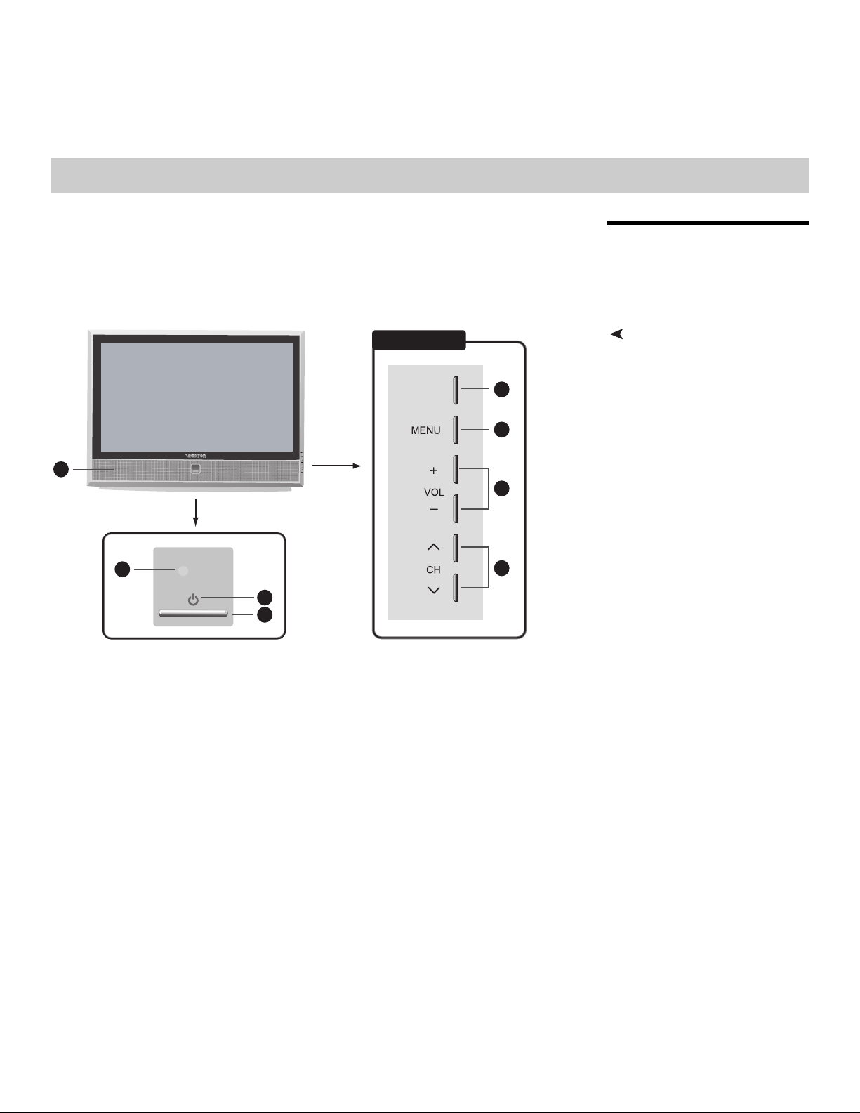
Figure 2-1 and Figure 2-2 show the locations of the DView controls, indicators and
connectors.
Right Side
2Controls and Functions
2.1 DView at a Glance
Controls and Indicators
8
5
6
7
Figure 2-1. DView Controls and Indicators
1. TV/AV Button (Input Source Selection)
2. MENU Selection Button
3. Volume Adjustment Buttons
4. Channel Selection Buttons
5. Remote Control Sensor
TV/AV
1
2
3
4
6. Power Indicator
Lights red to indicate that the DView is in standby mode; lights green to indicate normal
operation; flashes green when the DView receives a signal from the remote control.
7. Power Button
8. Speakers
Vidikron VL-26/VL-32 Owner’s Operating Manual 5
Controls and Functions
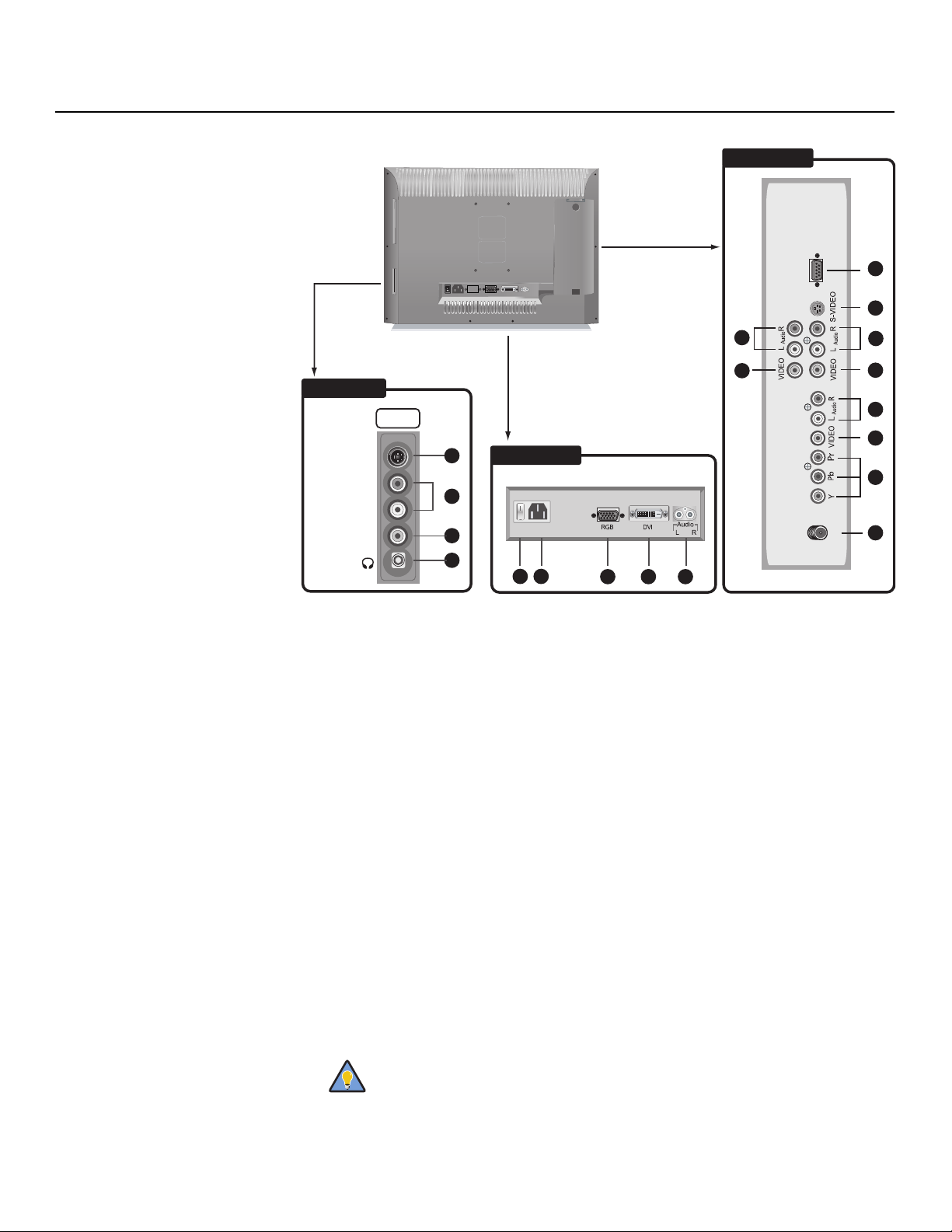
Connectors
➤
Right Side
Audio
INPUT2
S-VIDEOVIDEO
LR
Left Side
SERVICE
18
MONITOR-OUT
19
1
2
3
4
Rear
5 6
7 8
9
INPUT3
17
16
15
INPUT1
14
13
12
11
10
ANT
Figure 2-2. DView Connectors
1. INPUT 2 S-Video Input
Standard S-Video input for connecting a DVD player, satellite receiver or Super VHS
(S-VHS) VCR.
2. INPUT 2 Audio Input
3. INPUT 2 Composite Video Input
Standard composite video input for connecting a VCR, camcorder, laser disc player or
other composite video source.
4. Headphone Jack
5. Main Power Switch (VL-32 only)
6. Power Input (100 to 240 VAC)
Connect the DView to power here.
7. RGB HD
A 15-pin VGA connection to a personal computer. The DView automatically detects the
signal resolution: 480i, 480p, 576i, 576p, 720p or 1080i.
8. DVI/Computer Input (Digital)
HDCP-compliant digital video input for connecting a DVD player, personal computer or
HD tuner with a DVI or HDMI output.
For best results, do not run your DVD player in progressive mode.
Tip
6 Vidikron VL-26/VL-32 Owner’s Operating Manual

9. Audio Input (RGB/DVI)
Connect the audio output from your RGB or DVI source here.
10. ATSC DT V In p u t
75-ohm coaxial input for connecting a TV antenna or CATV system to the digital TV
tuner.
11. INPUT 3 Component Video (RCA connectors)
Standard-definition (480i/576i) or high-definition (720p/1080i), YPrPb component input.
This is the input for component video from sources such as DVD players.
12. INPUT 3 Composite Video Input
13. INPUT 3 Audio Input
Connect the audio output from your Input 3 source here.
14. INPUT 1 COMPOSITE VIDEO INPUT
15. INPUT 1 Audio Input
Connect the audio output from your Input 1 source here.
16. INPUT1 S-Video Input
17. RS-232 CONTROL PORT
A male, 9-pin D-sub connector for interfacing with a PC or home theater
automation/control system.
18. MONITOR-OUT (Audio)
19. MONITOR-OUT (Composite Video)
Controls and Functions
Vidikron VL-26/VL-32 Owner’s Operating Manual 7
Controls and Functions
TIMER
OFF
MENU
EXIT
ENTER
INPUT
1
INPUT
2
INPUT
3
2.2
DView Remote Control
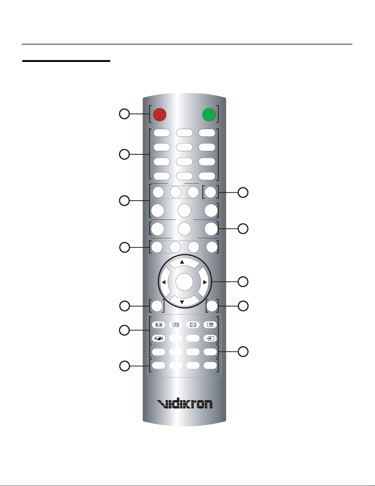
Figure 2-3 shows the DView remote control, and the paragraphs that follow describe its
functionality.
1
OFF ON
123
45
6
2
789
INPUT
_
SLEEP
TIMER
OFF
3
100
INPUT
0
SOURCE
INPUT
4
RGB
HD
MEMORY
CUST
6
ANA 4X3
ISF
NT
ASPECT RATIO
BOX
CH
LET
TVDVI
ISF
DAY
I-WIDE
5
ENTER
CH
MTS/SAP
10
12
VOL -
8
MENU
ASPECT SIZE POSITION PIP
P.MODE SWAP TV/AVS.SWAP
S.MODE SURRND
FC1 FC2 FC3 FC4
Figure 2-3. DView Remote Control
EXIT
MUTE
VOL +
7
9
11
8 Vidikron VL-26/VL-32 Owner’s Operating Manual

1. OFF / ON
Use these buttons to turn the DView on or off.
2. Numeric Buttons
Use these buttons to enter TV channel numbers or menu pass codes. Use the 100 button
to enter channel numbers above 99. Use the
numbers.
3. TIMER OFF Button
Press this button to set the sleep timer. Press it repeatedly to scroll through the available
options (Off, 10, 30, 60, 120 or 180 minutes).
4. Source Selection Buttons:
INPUT 1
Press this button to switch to Input 1.
INPUT 2
Press this button to switch to Input 2.
INPUT 3
Press this button to switch to Input 3.
DVI
Press this button to switch to the Digital Video input.
RGB HD
Press this button to switch to the RGB HD input.
TV
Press this button to switch to the Antenna/DTV/CATV input.
- button to enter DTV sub-channel
Controls and Functions
Input 1 and Input 2 have both S-Video and composite video connectors.
Note
5. Memory Preset Buttons:
CUST
Press to recall settings for the current input from the “Custom” memory preset.
ISF NT (Night)
Press to recall settings for the current input from the “ISF Night” memory preset.
ISF DAY
Press to recall settings for the current input from the “ISF Day” memory preset.
Input 3 has both component and composite video connectors.
To specify which connection type you are using – or to switch from one to
the other if equipment is connected to both – use the Input Selection menu
under Setup (refer to Input Selection on page 37).
Vidikron VL-26/VL-32 Owner’s Operating Manual 9

Controls and Functions
6. Aspect Ratio Selection Buttons:
ANA (Anamorphic)
For 16:9 DVDs or HDTV program material.
4X3 (Standard 4:3)
The input signal is scaled to fit 4:3 display mode in the center of the screen.
LETBOX (Letterbox)
Image in letterbox format is enlarged to fit 16:9 full screen display and the upper/lower
portions are “blanked off.”
I-WIDE (IntelliWide)
4:3 image is enlarged NON-linearly in horizontal direction to fit 16:9 full screen display.
7. Arrow Buttons ( , , , )
Use these buttons to select items or settings, adjust settings, change TV channels or
adjust sound volume.
ENTER
Press to select a highlighted menu item or confirm a changed setting.
8. MENU
Press this button to access the on-screen display (OSD) controls, or to exit the current
menu and return to the previous one.
9. EXIT
Press this button to hide the OSD controls, or display program information (when
available) if the OSD controls are already hidden.
10. Picture-In-Picture (PIP) Function Buttons
ASPECT
Press to change the aspect ratio of the PIP window from 4:3 to 16:9 or vice versa.
SIZE
Press to choose from three PIP window sizes.
POSITION
Press to choose the PIP window position (top left, top right, bottom left or bottom right
corner).
PIP
Press to change the PIP mode (picture-in-picture, picture-by-picture or off).
P. M O D E
Press to recall settings for the PIP input from either the “ISF Night” or “ISF Day” memory
preset.
S.SWAP
Press to switch between the main and PIP audio programs.
SWAP
Press to swap the main and PIP windows.
TV/AV
Press to switch to a different PIP video source.
10 Vidikron VL-26/VL-32 Owner’s Operating Manual
 Loading...