

Vidikron Vision 40ET, Vision 40 User Manual

Vision Model 40
Vision Model 40ET
Owner's Manual
®

Table of Contents
Table of Contents
Table of Contents .......................................................................................................... 1
Warning .......................................................................................................................... 4
Two Year Limited Warranty ....................................................................................... 6
Overview ........................................................................................................................ 8
Features ...................................................................................................................................... 8
Projector Exterior View ......................................................................................................... 10
Front / Upper Side ........................................................................................................................................ 10
Rear / Bottom Side ....................................................................................................................................... 11
Controls and Functions .......................................................................................................... 12
Control Panel ................................................................................................................................................ 12
Connector Panel ........................................................................................................................................... 14
Remote Control
Installation ................................................................................................................... 17
Remote Control ...................................................................................................................... 17
Projector .................................................................................................................................. 18
Connect the Power Cord ............................................................................................................................... 18
Adjust the Lens Zoom/Focus ring ................................................................................................................ 18
Adjust the height ........................................................................................................................................... 19
Installation For Vision Model 40 (With 1.38 - 1.63 Lens) ................................................... 20
Throw Distance Chart For Vision Model 40 (With 1.38 - 1.63 Lens) ................................ 21
............................................................................................................ 15
English
1

Vidikron Owner’s Manual
English
Installation For Vision Model 40ET (With 1.83 - 2.40 Lens) .............................................. 22
Throw Distance Chart For Vision Model 40ET (With 1.83 - 2.40 Lens) ........................... 23
Connecting ................................................................................................................... 24
Connecting Video Inputs ........................................................................................................ 25
Video / S-Video / Component (Interlaced Video) ....................................................................................... 25
Progressive Component (DTV Y/PB/PR) .................................................................................................. 26
RGBHV (DTV RGB) ................................................................................................................................... 27
Connecting a Computer or HDCP Compatible Video Device With DVI-I Output .......... 28
Basic Operation ........................................................................................................... 29
Turning on the Power ............................................................................................................. 29
Zoom/ Focusing ....................................................................................................................... 30
Selecting Video Memory ........................................................................................................ 30
Selecting Input Source ............................................................................................................ 31
Setting Menu ........................................................................................................................... 31
Selecting "ASPECT RATIO" ................................................................................................ 32
PIP/ POP function ................................................................................................................... 32
Turning off the Power ............................................................................................................ 33
Menu ............................................................................................................................. 34
Using the Menu ....................................................................................................................... 34
Main Menu .............................................................................................................................. 35
Picture Quality Adjustments ................................................................................................. 35
2

Table of Contents
Image Options 1 ...................................................................................................................... 36
Input Select ................................................................................................................................................... 36
Aspect Ratio ................................................................................................................................................. 37
Image Option 2 ........................................................................................................................ 38
Projector Status ....................................................................................................................... 39
Install ........................................................................................................................................ 40
Service ...................................................................................................................................... 41
White Balance ............................................................................................................................................... 41
Blue Enable ................................................................................................................................................... 42
Reset Lamp Timer ........................................................................................................................................ 42
Additional Information ............................................................................................... 43
Replace the Lamp (Contact your Vidikron Dealer) ............................................................ 43
Troubleshooting ...................................................................................................................... 44
Specifications ........................................................................................................................... 46
Dimensions ............................................................................................................................... 48
RS-232 Setup ........................................................................................................................... 49
RS-232C Control Codes ............................................................................................................................... 49
PC Out Adapter ............................................................................................................................................ 50
English
3

English
Vidikron Owner’s Manual
Vidikron Vision Model 40/ Vision Model 40ET Owner’s Manual
Thank you for your purchase of this quality Vidikron video projector. It has been designed to provide you with the quality of video that is
expected in a high performance home theater. For the best results, please read this manual carefully as it is your guide through the menus
and operation.
Warning
This symbol is intended to alert the user to the presence of uninsulated
CAUTION
RISK OFELECTRIC SHOCK
DO NOTOPEN
" dangerous voltage " within the product's enclosure that may be of sufficient magnitude to constitute a risk of electric shock.
CAUTION: TOREDUCE THE RISKOF ELECTRIC SHOCK.
DO NOTREMOVE COVER (ORBACK)
NO USERSERVICEABLE PARTSINSIDE.
REFER SERVICINGTO QUALIFIED SERVICEPERSONNEL.
This equipment has been tested and found to comply with the limits for a Class B digital device, pursuant to Part 15 of the FCC Rules. These
limits are designed to provide reasonable protection against harmful interference in a residential installation.
1. Read these instructions.
2. Keep these instructions.
3. Heed all warnings.
4. Do not use this projector near water, outdoors or otherwise exposed to the elements.
5. Clean only with a dry cloth.
4
This symbol is intended to alert the user to the presence of important
operating and maintenance (servicing) instructions in the literature
accompanying the appliance.

Warning
6. Do not block any ventilation openings.
7. Do not install near any heat sources such as radiators, heat registers, stoves, or other apparatus (including amplifiers) that produce
heat.
8. Do not defeat the safety feature of the polarized or grounding type plug. A polarized type plug has two blades with one wider than the
other. A grounding type plug has two blades and a third grounding prong. The third prong is provided for your safety. If the provided
plug does not fit into your outlet, consult an electrician for the replacement of the obsolete outlet.
9. Do not connect the RJ-11, RS-232 jack to a telephone line connection.
10. The 12V trigger outputs 12V DC for triggering. Do not connect to any other power input or output. This could cause damage to this
unit.
11. Only use accessories specified by Vidikron.
12. Keep the packing material in case the projector should ever need to be shipped.
13. Unplug this projector during lightning storms or when it will not be used for an extended period of time.
14. The lamp becomes extremely hot during operation. Allow the projector to cool down for approximately 45 minutes prior to removing
the lamp assembly for replacement. Do not operate lamps beyond the rated lamp life. Excessive operation of lamps beyond rated life
could cause them to explode in rare occasions.
Refer all servicing to qualified service personnel. Servicing is required when the projector has been damaged in any way, objects have fallen
or spilled into the projector, the projector has been exposed to rain or moisture, does not operate normally, or has been dropped.
English
5

Vidikron Owner’s Manual
English
Two Year Limited Warranty
Congratulations on your purchase of a Vidikron video product and welcome to the Vidikron family! With proper installation, setup and care,
you should enjoy many years of unparalleled video performance.
This is a LIMITEDWARRANTY as defined in the Magnuson-Moss Warranty Act. Please read it carefully and retain it with your other
important documents.
WHAT IS COVERED UNDER THE TERMS OF THIS LIMITED WARRANTY:
SERVICE LABOR: Vidikron will pay for service labor by a Vidikron Authorized Service Center when needed as a result of a
manufacturing defect for a period of two (2) years from the effective date of delivery to the end user (excluding the lamp).
PAR TS: (Not including the lamp) Vidikron will provide new or rebuilt replacement parts for the parts that fail due to defects in materials or
workmanship for a period of two (2) years from the effective date of delivery to the end user. Such replacement parts are then subsequently
warranted for the remaining portion (if any) of the original warranty period.
PROJECTOR LAMP: Vidikron will pay for service labor by a Vidikron Authorized Service Center when needed as a result of a
manufacturing defect for a period of six (6) months or 1000 hours, whichever comes first, from the effective date of delivery to the end user.
In addition, Vidikron will provide a new or rebuilt replacement lamp for the lamp that fails due to defects in materials or workmanship for a
period of six (6) months or 1000 hours, whichever comes first, from the effective date of delivery to the end user. Such replacement lamps
are then subsequently warranted for the remaining portion (if any) of the original warranty period.
WHAT IS NOT COVERED UNDER THE TERMS OF THIS LIMITED WARRANTY:
This Limited Warranty only covers failure due to defects in materials and workmanship that occur during normal use and does not cover
normal maintenance. This Limited Warranty does not cover cabinets or any appearance items; failure resulting from accident, misuse, abuse,
neglect, mishandling, misapplication, faulty or improper installation or setup adjustments; improper maintenance, alteration, improper use
of any input signal; damage due to lightning or power line surges, spikes and brownouts; damage that occurs during shipping or transit; or
damage that is attributed to acts of God. In the case of remote control units, damage resulting from leaking, old, damaged or improper
batteries is also excluded from coverage under this Limited Warranty.
CAUTION: THIS LIMITED WARRANTY ONLY COVERS VIDIKRON PRODUCTS PURCHASED FROM VIDIKRON
AUTHORIZED DEALERS. ALL OTHER PRODUCTS ARE SPECIFICALLY EXCLUDED FROM COVERAGE UNDER THIS
LIMITED WARRANTY. MOREOVER, DAMAGE RESULTING DIRECTLY OR INDIRECTLY FROM IMPROPER INSTALLATION
OR SETUP IS SPECIFICALLY EXCLUDED FROM COVERAGE UNDER THIS LIMITED WARRANTY.
6

Two Year Limited Warranty
RIGHTS, LIMITS AND EXCLUSIONS:
Vidikron limits its obligations under any implied warranties under state laws to a period not to exceed the warranty period. There are no
express warranties. Vidikron also excludes any obligation on its part for incidental or consequential damages related to the failure of this
product to function properly. Some states do not allow limitations on how long an implied warranty lasts, and some states do not allow the
exclusion or limitation of incidental or consequential damages. So the above limitations or exclusions may not apply to you. This warranty
gives you specific legal rights, and you may also have other rights that vary from state to state.
EFFECTIVE WARRANTY DATE:
This warranty begins on the effective date of delivery to the end user. For your convenience, keep the original bill of sale as evidence of the
purchase date.
IMPORTANT: WARRANTY REGISTRATION:
Please fill out and mail your warranty registration card. It is imperative that Vidikron knows how to reach you promptly if we should
discover a safety problem or product update for which you must be notified.
CONTACT A VIDIKRON AUTHORIZED SERVICE CENTER TO OBTAIN SERVICE
Repairs made under the terms of this Limited Warranty covering your Vidikron video product will be performed at the location of the product, during usual working hours, providing location of product is within normal operating distance from a Vidikron Authorized Service Center. In some instances it may be necessary for the product to be returned to the Vidikron factory for repairs. If, solely in Vidikron's judgment,
location of product to be repaired is beyond normal operating distance of the closest Vidikron Authorized Service Center, or the repair
requires the unit be returned to the Vidikron factory, it is the owner's responsibility to arrange for shipment of the product for repair. These
arrangements must be made through the selling Vidikron dealer. If this is not possible, contact Vidikron directly to locate an authorized Vidikron representative who will assist you in getting a return authorization. Vidikron will return product transportation prepaid in the United
States, unless no product defect is discovered. In that instance, shipping costs will be the responsibility of the owner.
ADDITIONAL INFORMATION:
To locate the name and address of the nearest VIDIKRON authorized service location, or for additional information about this warranty,
please call or write:
VIDIKRON
Attn: Customer Service Department
2900 Faber Street
Union City, CA 94587
Ph: (510) 324-5900
Fax: (510) 324-5905
7
English

Vidikron Owner’s Manual
English
Overview
Features
■ 1280 x 720 Widescreen Native 16:9 Resolution HD-2 DMD
■ Integrated Video Processing With 3:2 Pulldown
■ 950 ANSI Lumens/ 1600:1 Contrast Ratio
■ Multiple Aspect Ratios with Intelliwide Mode
■ HDTV Ready
480P, 1080i and 720P (576P PAL Version) formats are all compatible with this unit (via an external DTV decoder, not provided).
■ DVI-I Input with HDCP
■ 9-Point White Balance System for Excellent Gray Scale Tracking
■ Direct IR and RS-232 Control
■ ‘Cat’s Eye’ Optical System for Enchanced Contrast and Black Levels
■ Two Lens Options with Variable Throw Distances for Versatile Installation Convenience
■ De-interlacing with 3:2 Pull-down
Using Vidikron’s proprietary de-interlacing technology, this projector provides exceptional scaling and film to video (3:2 pulldown) conversion for the most artifact-free images possible.
TM
Display Device
8

■ PIP/ PBP function
Picture in picture/ Picture by picture functions allow you to display two inputs on the screen at the same time.
■ Video Memory
This projector allows the user to store up to three different settings per input.
Overview
English
9
English
Vidikron Owner’s Manual
Projector Exterior View
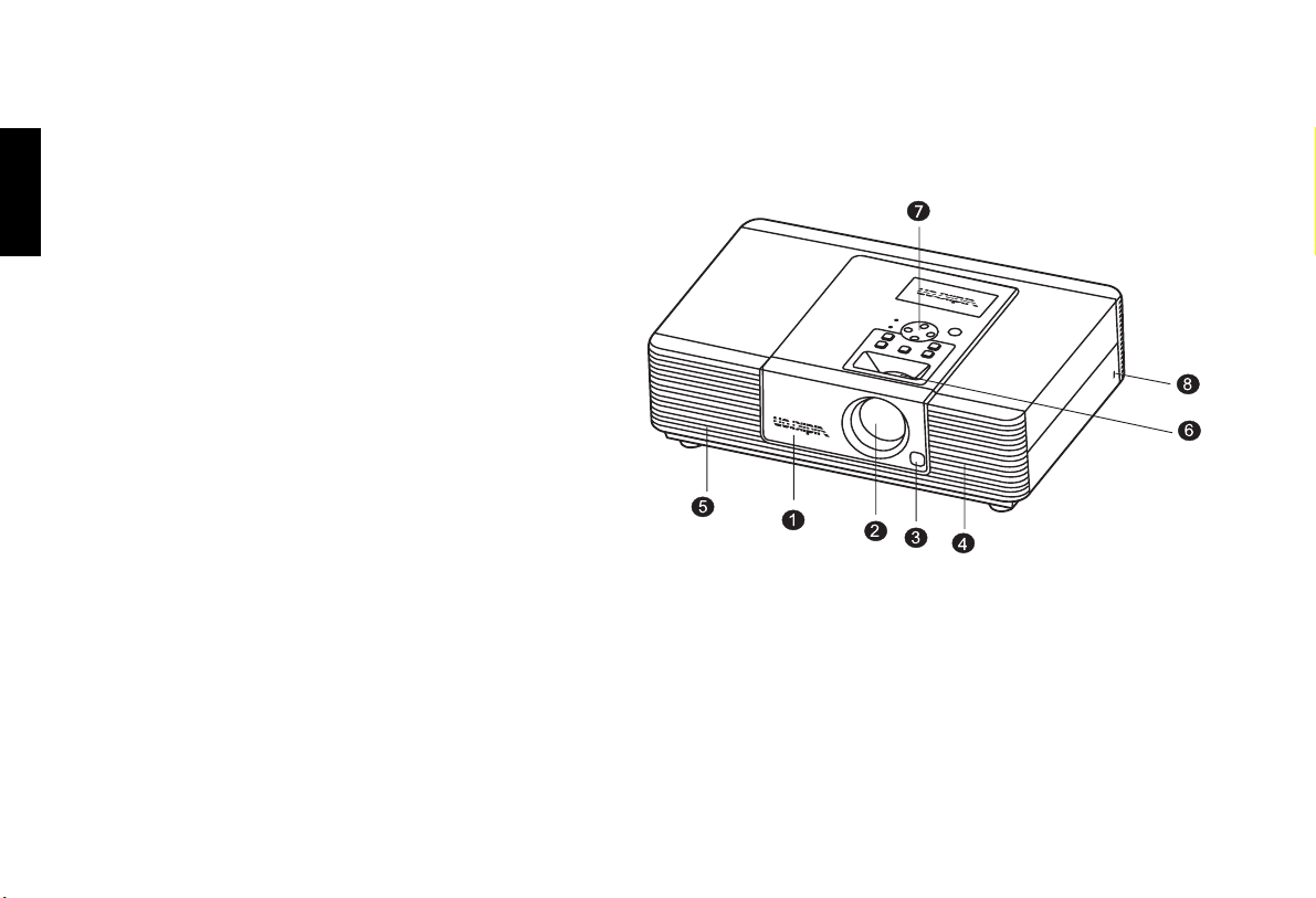
Front / Upper Side
1. Front Lamp Cover
Remove this cover when replacing the lamp. (See page 43.)
2. Projection Lens
3. Front IR Sensor
4. Ventilation Holes (intake)
5. Ventilation Holes (exhaust)
6. Focus Ring and Zoom Ring Access
Adjusts the focus and zoom of image.
7. Control Panel
Shows lamp status and whether the projector is on or off.
For more details, see "Control Panel" on page 12.
8. Kensington Lock
This lock can withstand 150 N of force.
10
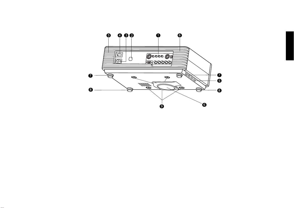
Rear / Bottom Side
Overview
English
1. Connector Panel
For more details, see "Connector Panel" on page 14.
2. Back IR Sensor
3. AC Power IN Socket
4. AC Power Switch
AC main power switch.
5. Ventilation Holes (exhaust)
6. Ventilation Holes (intake)
7. Rear Adjusters
Adjusts the height or projection angle.
8. Front Adjusters
Adjusts the height or projection angle.
9. Ceiling Mount Holes
The connecting holes for ceiling mount device.
11

English
Vidikron Owner’s Manual
Controls and Functions
Control Panel
12

Overview
1. STANDBY/ON
Press this key for ONE second to turn on the unit when it is in the
standby mode. Or press this key to turn off this unit when it is on.
2. INPUT
Switches input sources sequentially.
3. MEMORY
Sequentially recalls settings 1 ~ 3 saved to memory. (Please see
"Selecting Video Memory" on page 30.)
4. MENU
Turns the on-screen display control menu on or off.
5. ENTER
Enters settings for items shown in the menu.
6. EXIT
Exits and saves the setting(s) of items in the menu.
7. ARROW (c/e/d/f)
Use to select the menu or to make various adjustments.
8. POWER LED
Indicates power status
■ Lit orange when the AC power cord is plugged into the wall outlet
(standby mode). Once in the standby mode, you can press the
STANDBY/ON key on the projector or the ON key on the remote
control for ONE second to turn on the projector.
■ Lit green when the power is turned on (operational mode).
■ Flashes orange for the first 30 seconds after powering up, indicating
that the lamp is warming up.
■ Flashes green for one minute after the projector is turned off to
indicate that the lamp is cooling down.
9. LAMP LED
Indicates the status of lamp.
■ Lit red when the lamp has developed a problem. Please contact your
Vidikron dealer for assistance.
10. Zoom Ring
Adjusts the size of image
■ Rotate clockwise to enlarge the image or rotate counterwise to make
the image smaller.
11. Focus Ring
Adjust the focus of the projected images.
English
13
Vidikron Owner’s Manual
English
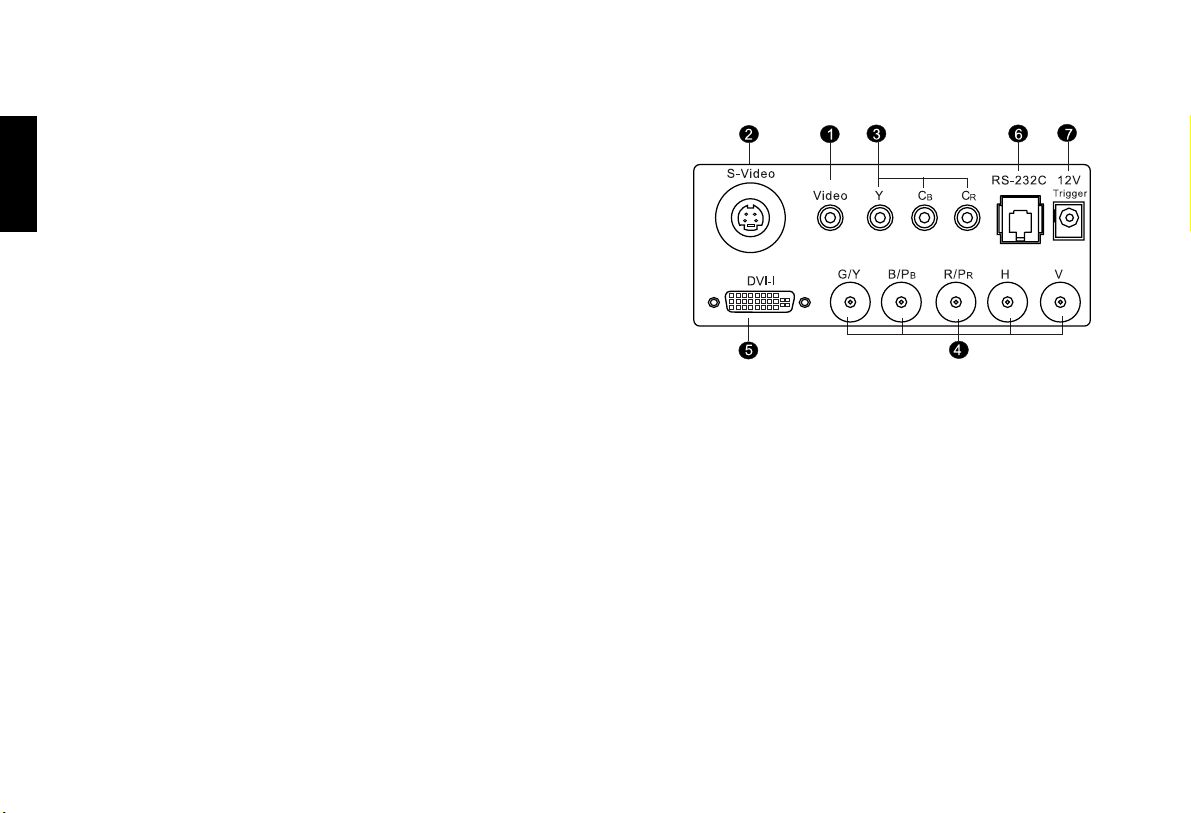
Connector Panel
1. Video (RCA Jack)
Composite video signal input.
2. S-Video (mini DIN 4-pin)
Y/C (S-video) signal input
3. Component (RCA Jacks)
480i Component (Y/CB/CR) video signal input
4. RGB/ HDTV (BNC) or Progressive Scan DVD players
DTV Y/PB/PR or DTV RGB video signal input.
5. DVI-I
Digital/ Analog signal input.
6. RS-232C (RJ-11 Jack)
RS-232C control signal input.
7. 12v Trigger (mini jack with the diameter of 5.5 mm outside and 2.5 mm inside)
+12V output, active when the projector is turned on.
14
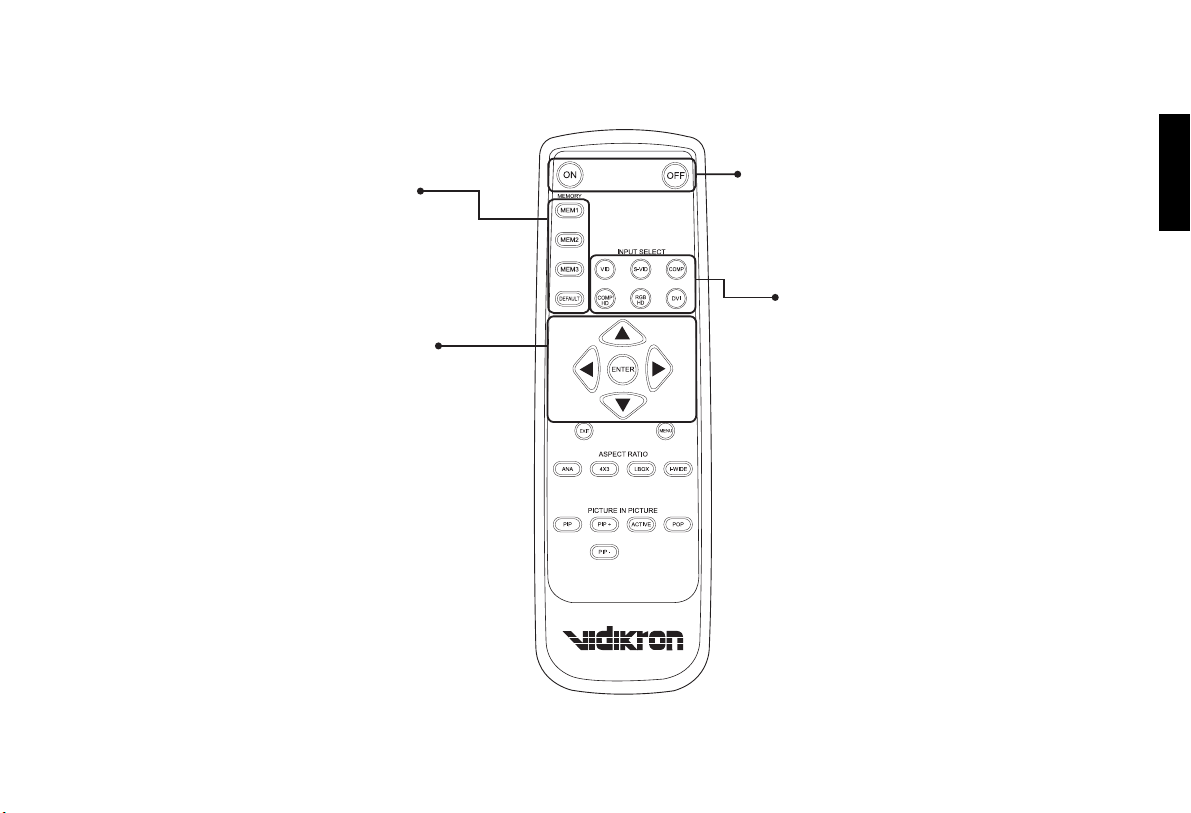
Remote Control
MEMORY
M1, M2, M3, DEFAULT
Recall video memory sequentially (see "Selecting
Video Memory" on page 30)
ARROW (c,e,d,f)
Use to select the menu or to make various
adjustments.
ENTER
Enter the setting of items in the menu.
ON
Hold down this button for ONE second to turn
on the unit.
OFF
Press this button to turn off the unit.
INPUT SELECT
VIDEO
Composite video signal input
S-VIDEO
S-Video signal input
COMP
Component Y/CB/CR input
COMP HD
DTV Y/PB/PR signal input
RGB HD
DTV RGBHV signal input
DVI
Digital/ Analog signal input
Overview
English
15
 Loading...