

Vidikron Vision 30, Vision 30ET CineWide, Vision 30 CineWide Owner's Operating Manual

OWNER’S OPERATING MANUAL
DLP™ PROJECTORS
Vision Model 30
Vision Model 30ET
Vision Model 30 CineWide™
Vision Model 30ET CineWide™
30
VERSION 2.0


TWO YEAR LIMITED WARRANTY
For Projectors, Video Processors and Controllers
Congratulations on your purchase of a Vidikron video product and welcome to the Vidikron family! With proper installation, setup
and care, you should enjoy many years of unparalleled video performance.
This is a LIMITED WARRANTY as defined in the Magnuson-Moss Warranty Act. Please read it carefully and retain it with your other
important documents.
WHAT IS COVERED UNDER THE TERMS OF THIS LIMITED WARRANTY:
SERVICE LABOR: Vidikron will pay for service labor by Vidikron Authorized Service Center when needed as a result of manufacturing
defect for a period of two (2) years from the effective date of delivery to the end user (excluding the lamp).
Y
PARTS (not including the lamp): Vidikron will provide new or rebuilt replacement parts for the parts that fail due to defects in
materials or workmanship for a period of two (2) years from the effective date of delivery to the end user. Such replacement parts
are then subsequently warranted for the remaining portion (if any) of the original warranty period.
PROJECTOR LAMP: Vidikron will pay for service labor by a Vidikron Authorized Service Center when needed as a result of a
manufacturing defect for a period of six (6) months or 1000 hours, whichever comes first, from the effective date of delivery to the
end user. In addition, Vidikron will provide a new or rebuilt replacement lamp for the lamp that fails due to defects in materials or
workmanship for a period of six (6) months or 1000 hours, whichever comes first, from the effective date of delivery to the end user.
Such replacement lamps are then subsequently warranted for the remaining portion (if any) of the original warranty period.
WHAT IS NOT COVERED UNDER THE TERMS OF THIS LIMITED WARRANTY:
IMINAR
This Limited Warranty only covers failure due to defects in materials and workmanship that occur during normal use and does not
cover normal maintenance. This Limited Warranty does not cover cabinets or any appearance items; failure resulting from
accident, misuse, abuse, neglect, mishandling, misapplication, faulty or improper installation or setup adjustments; improper
maintenance, alteration, improper use of any input signal; damage due to lightning or power line surges, spikes and brownouts;
damage that occurs during shipping or transit; or damage that is attributed to acts of God. In the case of remote control units,
damage resulting from leaking, old, damaged or improper batteries is also excluded from coverage under this Limited Warranty.
CAUTION: THIS LIMITED WARRANTY ONLY COVERS VIDIKRON PRODUCTS PURCHASED FROM VIDIKRON AUTHORIZED DEALERS.
ALL OTHER PRODUCTS ARE SPECIFICALLY EXCLUDED FROM COVERAGE UNDER THIS WARRANTY. MOREOVER, DAMAGE
RESULTING DIRECTLY OR INDIRECTLY FROM IMPROPER INSTALLATION OR SETUP IS SPECIFICALLY EXCLUDED FROM COVERAGE
UNDER THIS LIMITED WARRANTY. IT IS IMPERATIVE THAT INSTALLATION AND SETUP WORK BE PERFORMED ONLY BY AN
AUTHORIZED VIDIKRON DEALER TO PROTECT YOUR RIGHTS UNDER THIS WARRANTY. THIS WILL ALSO ENSURE THAT YOU ENJOY
THE FINE PERFORMANCE OF WHICH YOUR VIDIKRON PRODUCT IS CAPABLE WHEN INSTALLED AND CALIBRATED BY VIDIKRON
AUTHORIZED PERSONNEL.
RIGHTS, LIMITS AND EXCLUSIONS:
Vidikron limits its obligations under any implied warranties under state laws to a period not to exceed the warranty period. There
are no express warranties. Vidikron also excludes any obligation on its part for incidental or consequential damages related to the
failure of this product to function properly. Some states do not allow limitations on how long an implied warranty lasts, and some
states do not allow the exclusion or limitation of incidental or consequential damages. So the above limitations or exclusions may
not apply to you. This warranty gives you specific legal rights, and you may also have other rights that vary from state to state.
PRE
L
Vidikron Vision 30 Series Owner’s Operating Manual iii

EFFECTIVE WARRANTY DATE:
This warranty begins on the effective date of delivery to the end user. For your convenience, keep the original bill of sale as
evidence of the purchase date.
IMPORTANT -- WARRANTY REGISTRATION:
Please fill out and mail your warranty registration card. It is imperative that Vidikron knows how to reach you promptly if we should
discover a safety problem or product update for which you must be notified.
CONTACT A VIDIKRON AUTHORIZED SERVICE CENTER TO OBTAIN SERVICE:
Y
Repairs made under the terms of this Limited Warranty covering your Vidikron video product will be performed at the location of
the product, during usual working hours, providing location of product is within normal operating distance from a Vidikron
Authorized Service Center. In some instances it may be necessary for the product to be returned to the Vidikron factory for repairs.
If, solely in Vidikron’s judgment, location of product to be repaired is beyond normal operating distance of the closest Vidikron
Authorized Service Center, or the repair requires the unit be returned to the Vidikron factory, it is the owner’s responsibility to
arrange for shipment of the product for repair. These arrangements must be made through the selling Vidikron Dealer. If this is not
possible, contact Vidikron directly for a Return Authorization number and shipping instructions. Vidikron will return product
transportation prepaid in the United States, unless no product defect is discovered. In that instance, shipping costs will be the
responsibility of the owner.
COPYRIGHT AND TRADEMARKS:
© Copyright 2006 Vidikron, a Runco International Company. This document contains proprietary information protected by
copyright, trademark and other intellectual property laws. All rights are reserved. No part of this manual may be reproduced by any
mechanical, electronic or other means, in any form, without prior written permission of the manufacturer.
Vidikron, Vision, IntelliWide, Imagix, DView and CSMS are trademarks of Runco, LLC. All other trademarks and registered
trademarks used in this document are the property of their respective owners.
Vidikron products are manufactured under one or more of the following patents: US. Patent 6755540 and Other Patents Pending.
IMINAR
L
PRE
iv Vidikron Vision 30 Series Owner’s Operating Manual

ADDITIONAL INFORMATION:
To locate the name and address of the nearest Vidikron Authorized Service Center, or for additional information about this Limited
Warranty, please call or write:
VIDIKRON
Attn: Customer Service Department
2900 Faber Street
Union City, CA 94587
Ph: (510) 324-5900
Fax: (510) 324-5905
Toll Free: (888) 4VIDIKRON
VIDIKRON PRODUCT INFORMATION
RETAIN THIS INFORMATION FOR YOUR RECORDS
Y
IMINAR
_________________________________________________________ ________________________________________
L
Model Purchased Date
____________________________________________________________________________________________________________
Serial Number
____________________________________________________________________________________________________________
Vidikron Authorized Dealer Name
____________________________________________________________________________________________________________
PRE
Address
____________________________________________ __________________ ________________________
City State/Province Postal Code
____________________________________________ _______________________________________________________
Phone Fax
Vidikron Vision 30 Series Owner’s Operating Manual v
Safety Precautions
Thank you for your purchase of this quality Vidikron video projector! It has been designed to provide you with the quality of video
that is expected in a home theater. For the best performance, please read this manual carefully as it is your guide through the
menus and operation.
WAR NING
CAUTION
RISK OFELECTRIC SHOCK
DO NOTOPEN
TO REDUCE THE RISK OF ELECTRIC SHOCK
DO NOT REMOVE COVER (OR BACK)
NO USER SERVICEABLE PARTS INSIDE.
REFER SERVICING TO QUALIFIED
This equipment has been tested and found to comply with the limits for a Class B digital device, pursuant to Part 15 of the FCC
Rules. These limits are designed to provide reasonable protection against harmful interference in a residential installation.
1. Read these instructions.
2. Keep these instructions.
3. Heed all warnings.
4. Do not use this equipment near water, outdoors or otherwise exposed to the elements.
5. Clean only with a dry cloth.
6. Do not block any ventilation openings.
CAUTION:
SERVICE PERSONNEL.
This symbol is intended to alert the user to the presence of
uninsulated “dangerous voltage” within the product’s enclosure that
may be of sufficient magnitude to constitute a risk of electric shock.
This symbol is intended to alert the user to the presence of important
operating and maintenance (servicing) instructions in the literature
accompanying the appliance.
Y
IMINAR
L
7. Do not install near any heat sources such as radiators, heat registers, stoves, or other apparatus (including amplifiers) that
produce heat.
8. Do not defeat the safety feature of the polarized or grounding type plug. A polarized type plug has two blades with one wider
than the other. A grounding type plug has two blades and a third grounding prong. The third prong is provided for your safety.
If the provided plug does not fit into your outlet, consult an electrician for the replacement of the obsolete outlet.
9. The 12V trigger only outputs DC 12V signal for triggering. Do not connect to any other power input or output. This could cause
damage to this unit.
10. Only use accessories specified by Vidikron.
11. Keep the packing material in case the equipment should ever need to be shipped.
12. Unplug this projector during lightning storms or when it will not be used for an extended period of time.
13. The lamp becomes extremely hot during operation. Allow the projector to cool down for approximately 45 minutes prior to
removing the lamp assembly for replacement. Do not operate lamps beyond the rated lamp life. Excessive operation of lamps
beyond rated life could cause them to explode in rare occasions.
14. Refer all servicing to qualified service personnel. Servicing is required when the projector has been damaged in any way,
objects have fallen or spilled into the projector, the projector has been exposed to rain or moisture, does not operate normally,
or has been dropped.
PRE
vi Vidikron Vision 30 Series Owner’s Operating Manual

1Table of Contents
TWO YEAR LIMITED WARRANTY ............................................................................................. iii
Safety Precautions ................................................................................................................... vi
1. Introduction ........................................................................................................................ 1
About This Manual ............................................................................................................................................ 1
Target Audience......................................................................................................................................... 1
If You Have Comments About This Manual... .................................................................................. 1
Textual and Graphic Conventions ....................................................................................................... 1
Using This Manual ............................................................................................................................................. 2
Description, Features and Benefits ............................................................................................................. 3
Key Features and Benefits....................................................................................................................... 4
Parts List ........................................................................................................................................................ 4
2. Controls and Functions ...................................................................................................... 5
Vision 30 at a Glance ........................................................................................................................................ 5
Vision 30 Connector Panel ............................................................................................................................. 8
Built-In Keypad ................................................................................................................................................... 9
Vision 30 Remote Control ............................................................................................................................. 10
Remote Control/Built-In Keypad Functional Comparison ................................................................ 13
IMINAR
L
Y
3. Installation ........................................................................................................................ 15
Remote Control ................................................................................................................................................ 15
Notes on Batteries ...................................................................................................................................15
PRE
Notes on Remote Control Operation................................................................................................15
Quick Setup ....................................................................................................................................................... 16
Installation Considerations ..........................................................................................................................17
Installation Type.......................................................................................................................................17
Ambient Light ...........................................................................................................................................17
Throw Distance.........................................................................................................................................18
Vertical and Horizontal Position ......................................................................................................... 19
Folded Optics ............................................................................................................................................19
Other Considerations ............................................................................................................................. 20
Mounting the Vision 30 .................................................................................................................................20
Floor Mounting (Upright) ..................................................................................................................... 20
Ceiling Mounting (Inverted) ................................................................................................................ 20
Adjusting the Projector Height or Projection Angle................................................................... 20
Installing the Optional CineWide Lens Mount ......................................................................................21
Vidikron Vision 30 Series Owner’s Operating Manual vii

Table of Contents
Connections to the Vision 30 ...................................................................................................................... 22
Connector Panel Access ........................................................................................................................22
Connecting Source Components to the Vision 30 ...................................................................... 22
RS-232 Controller Connection ............................................................................................................26
Connecting 12-volt Trigger Output to External Theater Equipment....................................27
Connecting to AC Power....................................................................................................................... 27
Removing the Lens Cap ................................................................................................................................27
Turning On the Power ...................................................................................................................................28
Changing the OSD Language ..................................................................................................................... 28
Adjusting the Picture Orientation .............................................................................................................28
Zoom and Focus Adjustments ....................................................................................................................28
Installing and Adjusting the CineWide Anamorphic Lens ................................................................29
Installing the Anamorphic Lens.......................................................................................................... 30
Adjusting the Anamorphic Lens.........................................................................................................30
4. Operation .......................................................................................................................... 33
Y
Selecting Video Memory ............................................................................................................................... 33
Selecting an Aspect Ratio .............................................................................................................................33
Selecting An Input Source ............................................................................................................................33
Using Picture-In-Picture and Picture-By-Picture (PIP/PBP) ...............................................................33
Turning Off the Power ...................................................................................................................................34
Using the On-Screen Menus ........................................................................................................................34
Main Menu .................................................................................................................................................36
Picture Adjust ...........................................................................................................................................36
Image Option ............................................................................................................................................41
Projector Status ........................................................................................................................................ 44
PRE
5. Maintenance and Troubleshooting ................................................................................53
6. Serial Communications .................................................................................................... 57
Installation..................................................................................................................................................45
Service..........................................................................................................................................................46
ISF Calibration ...........................................................................................................................................50
Lamp Replacement .........................................................................................................................................53
Troubleshooting Tips .....................................................................................................................................54
RS-232 Connection and Port Configuration ..........................................................................................57
Serial Command Syntax ................................................................................................................................57
IMINAR
L
7. Specifications .................................................................................................................... 61
Vision 30 Specifications .................................................................................................................................61
Vision 30 Dimensions .....................................................................................................................................63
APPENDIX A. Personalizing the ISF Splash Screen on the Vision 30 ................................ A-1
viii Vidikron Vision 30 Series Owner’s Operating Manual

1List of Figures
2-1. Vision 30 Front/Side/Top View . . . . . . . . . . . . . . . . . . . . . . . . . . . . . . . . . . . . . . . . . . . . . . . . . . . . . . . . . . 5
2-2. Vision 30 Rear/Bottom/Side View . . . . . . . . . . . . . . . . . . . . . . . . . . . . . . . . . . . . . . . . . . . . . . . . . . . . . . . . 7
2-3. Vision 30 Connector Panel . . . . . . . . . . . . . . . . . . . . . . . . . . . . . . . . . . . . . . . . . . . . . . . . . . . . . . . . . . . . . . 8
2-4. Vision 30 Remote Control . . . . . . . . . . . . . . . . . . . . . . . . . . . . . . . . . . . . . . . . . . . . . . . . . . . . . . . . . . . . . . 10
2-5. Remote Control/Built-In Keypad Functional Cross-Reference . . . . . . . . . . . . . . . . . . . . . . . . . . . . 13
3-1. Estimating Throw Distance . . . . . . . . . . . . . . . . . . . . . . . . . . . . . . . . . . . . . . . . . . . . . . . . . . . . . . . . . . . . . 18
3-2. Projector Placement . . . . . . . . . . . . . . . . . . . . . . . . . . . . . . . . . . . . . . . . . . . . . . . . . . . . . . . . . . . . . . . . . . . 19
3-3. Folded Optics. . . . . . . . . . . . . . . . . . . . . . . . . . . . . . . . . . . . . . . . . . . . . . . . . . . . . . . . . . . . . . . . . . . . . . . . . . 19
3-4. Vision 30/CineWide with Anamorphic Lens Base Plate and
Ceiling Mounting Plate - Bottom View . . . . . . . . . . . . . . . . . . . . . . . . . . . . . . . . . . . . . . . . . . . . . . . . . . 21
3-5. HDMI/DVI Source Connections . . . . . . . . . . . . . . . . . . . . . . . . . . . . . . . . . . . . . . . . . . . . . . . . . . . . . . . . . 22
3-6. RGB Connections . . . . . . . . . . . . . . . . . . . . . . . . . . . . . . . . . . . . . . . . . . . . . . . . . . . . . . . . . . . . . . . . . . . . . . 23
3-7. Progressive Component Video Connections . . . . . . . . . . . . . . . . . . . . . . . . . . . . . . . . . . . . . . . . . . . . 24
3-8. Composite, S-Video and Component Video Connections . . . . . . . . . . . . . . . . . . . . . . . . . . . . . . . . 25
3-9. RS-232 Control System Connection. . . . . . . . . . . . . . . . . . . . . . . . . . . . . . . . . . . . . . . . . . . . . . . . . . . . . 26
3-10. Connecting the 12-Volt Trigger Output to Other Equipment . . . . . . . . . . . . . . . . . . . . . . . . . . . 27
3-11. Anamorphic Lens Mounting Assembly - Exploded View. . . . . . . . . . . . . . . . . . . . . . . . . . . . . . . . 29
4-1. Vision 30 OSD Menu Structure . . . . . . . . . . . . . . . . . . . . . . . . . . . . . . . . . . . . . . . . . . . . . . . . . . . . . . . . . 35
4-2. Typical PLUGE Pattern for Adjusting Brightness . . . . . . . . . . . . . . . . . . . . . . . . . . . . . . . . . . . . . . . . . 37
4-3. Typical Gray Bar Pattern for Adjusting Contrast . . . . . . . . . . . . . . . . . . . . . . . . . . . . . . . . . . . . . . . . . 38
PRE
4-4. Typical Color Bar Pattern for Adjusting Color Saturation and Tint . . . . . . . . . . . . . . . . . . . . . . . . 38
4-5. Typical Test Pattern for Adjusting Sharpness. . . . . . . . . . . . . . . . . . . . . . . . . . . . . . . . . . . . . . . . . . . . 40
IMINAR
L
Y
7-1. Vision 30 Dimensions . . . . . . . . . . . . . . . . . . . . . . . . . . . . . . . . . . . . . . . . . . . . . . . . . . . . . . . . . . . . . . . . . . 63
Vidikron Vision 30 Series Owner’s Operating Manual ix

List of Figures
Notes:
Y
IMINAR
L
PRE
x Vidikron Vision 30 Series Owner’s Operating Manual

1Introduction
This Owner’s Manual describes how to install, set up and operate the Vidikron Vision
Model
30 family of Digital Light Processing™ Projectors:
• Vision 30
• Vision 30ET (Extended Throw)
• Vision 30 CineWide™
• Vision 30ET CineWide™
Throughout this manual, all four projector models are referred to collectively as the “Vision
30.” Except where noted, the features and functions described in this manual are common to
all versions of this product.
most out of the Vision 30.
Vidikron has made every effort to ensure that this manual is accurate as of the date it was
printed. However, because of ongoing product improvements and customer feedback, it
may require updating from time to time. You can always find the latest version of this and
other Vidikron product manuals on-line, at www.Vidikron.com.
Y
IMINAR
Vidikron welcomes your comments about this manual. Send them to info@vidikron.com.
L
Text Conventions: The following conventions are used in this manual, in order to clarify the
information and instructions provided:
• Remote and built-in keypad button identifiers are set in upper-case bold type; for
example, “Press EXIT to return to the previous menu.”
• Computer input (commands you type) and output (responses that appear on-screen) is
shown in monospace (fixed-width) type; for example: “To change the aspect ratio to
Letterbox, type x063x <Enter>.”
• All keys with functional names are initial-capped, set in bold type and enclosed in angle
brackets. These keys are the following: <Enter>, <Spacebar>, <Control>,
<Esc> and <Tab>.
• <Enter> indicates that you may press either the RETURN or ENTER key on your keyboard
if it has both keys.
PRE
1.1
About This Manual
Target AudienceVidikron has prepared this manual to help home theater installers and end users get the
If You Have Comments About
This Manual...
Textual and Graphic
Conventions
In addition to these conventions, underlining, boldface and/or italics are occasionally used to
highlight important information, as in this example:
Note
Vidikron Vision 30 Series Owner’s Operating Manual 1
A carriage return must be used after each command or string.
Introduction
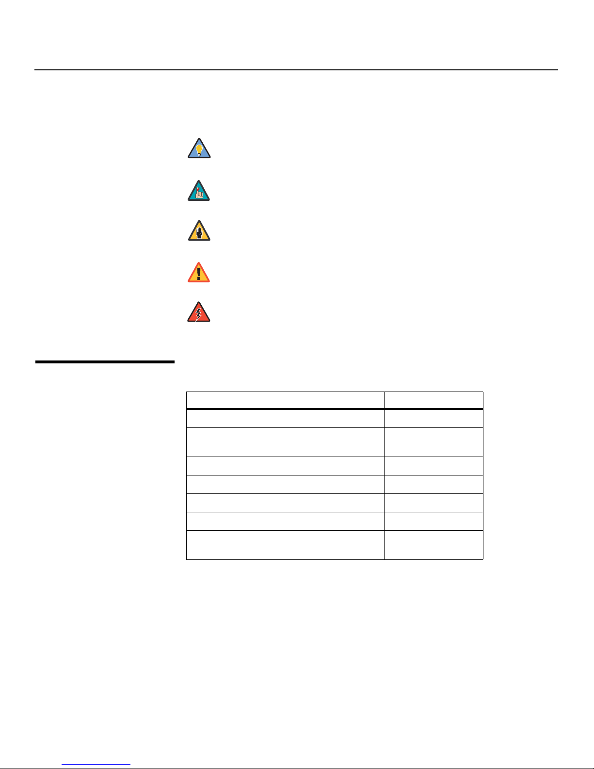
Graphic Conventions: These symbols appear in numerous places throughout the manual,
to emphasize points that you must keep in mind to avoid problems with your equipment or
injury:
1.2
Using This Manual
Tip
Note
Caution
TIPS highlight time-saving short cuts and helpful guidelines for using
certain features.
NOTES emphasize text with unusual importance or special significance.
They also provide supplemental information.
CAUTIONS alert users that a given action or omitted action can degrade
performance or cause a malfunction.
Y
WARNING
DANGER!
Use the following table to locate the specific information you need in this manual.
WARNINGS appear when a given action or omitted action can result in
damage to the equipment, or possible non-fatal injury to the user.
DANGER appears when a given action can cause severe injury or death.
IMINAR
If you need... ... Turn to page:
Information about obtaining service iv
L
General information about the Vision 30 Series DLP
Projectors
Installation instructions 15
First-time configuration instructions 28
PRE
Advanced configuration instructions 46
Troubleshooting tips 54
Specifications for the Vision 30 Series DLP
Projectors
3
61
2 Vidikron Vision 30 Series Owner’s Operating Manual

Introduction
The Vision 30 Series DLP Projectors offer the astounding picture quality and versatility
heretofore associated with more expensive projectors. Their 1280 x 720 native resolution
DLP light engine incorporates all-new technology for bright, pristine high-definition images.
With throw distances of 1.38 – 1.80:1 on the Vision Model 30 and 1.88 – 2.45:1 on the
longer-throw Model 30ET, both units offer the performance and installation flexibility
custom home theater enthusiasts have come to expect from Vidikron — all at a superb price
and packaged with outstanding build quality.
Advanced Vidikron Imagix™ digital video processing is engineered into these all-new
projection systems to achieve improved image quality even from standard video sources, in
addition to artifact-free scaling of higher resolution formats.
The Vision 30's illumination system incorporates Vidikron's exclusive DualV Stage
Illumination™ (DVSI™), which provides two light intensity levels to allow maximum flexibility
for screen size, ambient light conditions, brightness and contrast balance, and lamp life
preservation. It also has a newly-refined cooling system, which increases efficiency and
reduces noise levels.
The Vision 30 has been engineered to comply with Imaging Science Foundation™ (ISF)
standards for maximum home theater image quality. Vidikron's sophisticated parameters for
white balance and color gamut control have also been implemented for precise balance of
gray scale and color.
For uncompromising widescreen reproduction of movies originally filmed in the “scope”
(2.35:1) format, the Vision 30 can be equipped with Vidikron’s patent-pending CineWide™
technology, a combination of software, electronics and high-quality anamorphic optics.
CineWide maintains constant vertical height on the screen just as in a movie theater. When a
viewer transitions from 1.78:1 (16:9) program material to 2.35:1, the image simply gets wider
while full height is maintained.
IMINAR
L
Y
1.3
Description, Features and
Benefits
Note
Discrete IR and RS-232 control make custom installation seamless, while discrete source and
aspect ratio selection accommodate any automation control system.
CineWide requires the use of a 2.35:1 or similar aspect ratio superwide format
screen.
PRE
Vidikron Vision 30 Series Owner’s Operating Manual 3

Introduction
Key Features and Benefits The Vision 30 offers these key features and benefits:
Parts List Your Vision 30 is shipped with the following items. If any items are missing or damaged,
➤
• Native Resolution: 1280 x 720 (16:9 Native Aspect Ratio)
• DLP system using high-performance Digital Micromirror Device (DMD)
• 6-segment, 5x color wheel produces wide dynamic range and rich grayscale
• Picture in Picture / Picture by Picture functions allow you to display two inputs on the
screen at the same time
• HDMI Input with High-bandwidth Digital Content Protection (HDCP)
•HDTV Compatible
➤
please contact your Vidikron dealer or Vidikron Customer Service at (888) 4VIDIKRON.
• Vision 30 DLP Projector
•Remote Control Unit and two (2), AAA-size batteries
• AC Power Cords (North America, Europe, Asia)
• Source Connection Cables:
• Composite Video
•S-Video
• Component Video
• RGB (DB15HD-to-5 x BNC)
•HDMI to HDMI
•HDMI to DVI
• Warranty information and registration card
• Vidikron Vision 30 Series Owner’s Operating Manual (this document)
IMINAR
L
Y
Optional Accessories:
• CineWide™ technology (secondary anamorphic lens and motorized mount)
• Ceiling mount kit
PRE
4 Vidikron Vision 30 Series Owner’s Operating Manual
2. Controls and Functions
Figure 2-1 and Figure 2-2 show the key Vision 30 components.
IMINAR
L
78910
2.1
Vision 30 at a Glance
4
Y
5 6
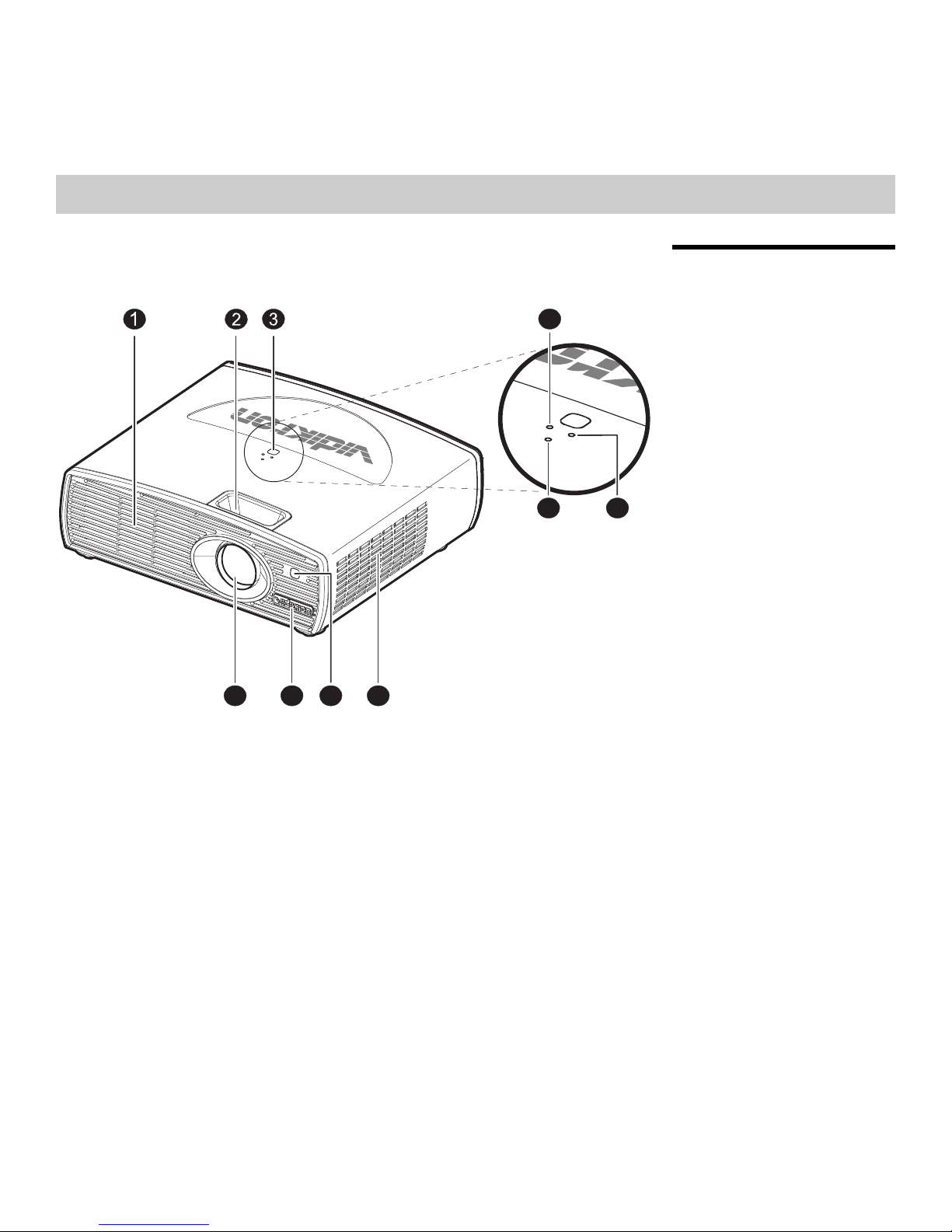
Figure 2-1. Vision 30 Front/Side/Top View
1. EXHAUST VENT
2. FOCUS AND ZOOM RING ACCESS
3. TOP IR SENSOR
4. LAMP LED
Indicates lamp status as follows:
• Off during normal operation
• Red when the lamp has exceeded its usage life or developed a problem.
• Flashes red when the fans are not working or the lamp cover is open
5. POWER/STANDBY LED
Indicates power status as follows:
• Orange when the projector is in standby mode
• Flashes orange for 45 seconds after the projector is turned on to indicate that the lamp
is warming up
• Green during normal operation
• Flashes green for 110 seconds after the projector is turned off to indicate that the lamp
is cooling down
Vidikron Vision 30 Series Owner’s Operating Manual 5
PRE

Controls and Functions
6. TEMP LED
Indicates fan status and internal temperature as follows:
• Off during normal operation
• Red when internal temperature is too high
• Flashes red when the fans are not working or the lamp cover is open
7. INTAKE VENT
8. FRONT IR SENSOR
9. VIDIKRON LOGO
The logo can be rotated to match the projector
orientation: inverted (ceiling-mounted) or upright.
To rotate the logo, grip it at the sides, pull it away
from the projector and rotate it 180 degrees.
10. PROJECTION LENS
Y
IMINAR
L
PRE
6 Vidikron Vision 30 Series Owner’s Operating Manual
1 2 3 4
MEMORY
MEMORY
AUTO
AUTO
MENU
SOURCE
POWER
/EXIT
/ENTER
POWER
/EXIT
/ENTER
MENU
SOURCE
Controls and Functions
9 10 9
PRE
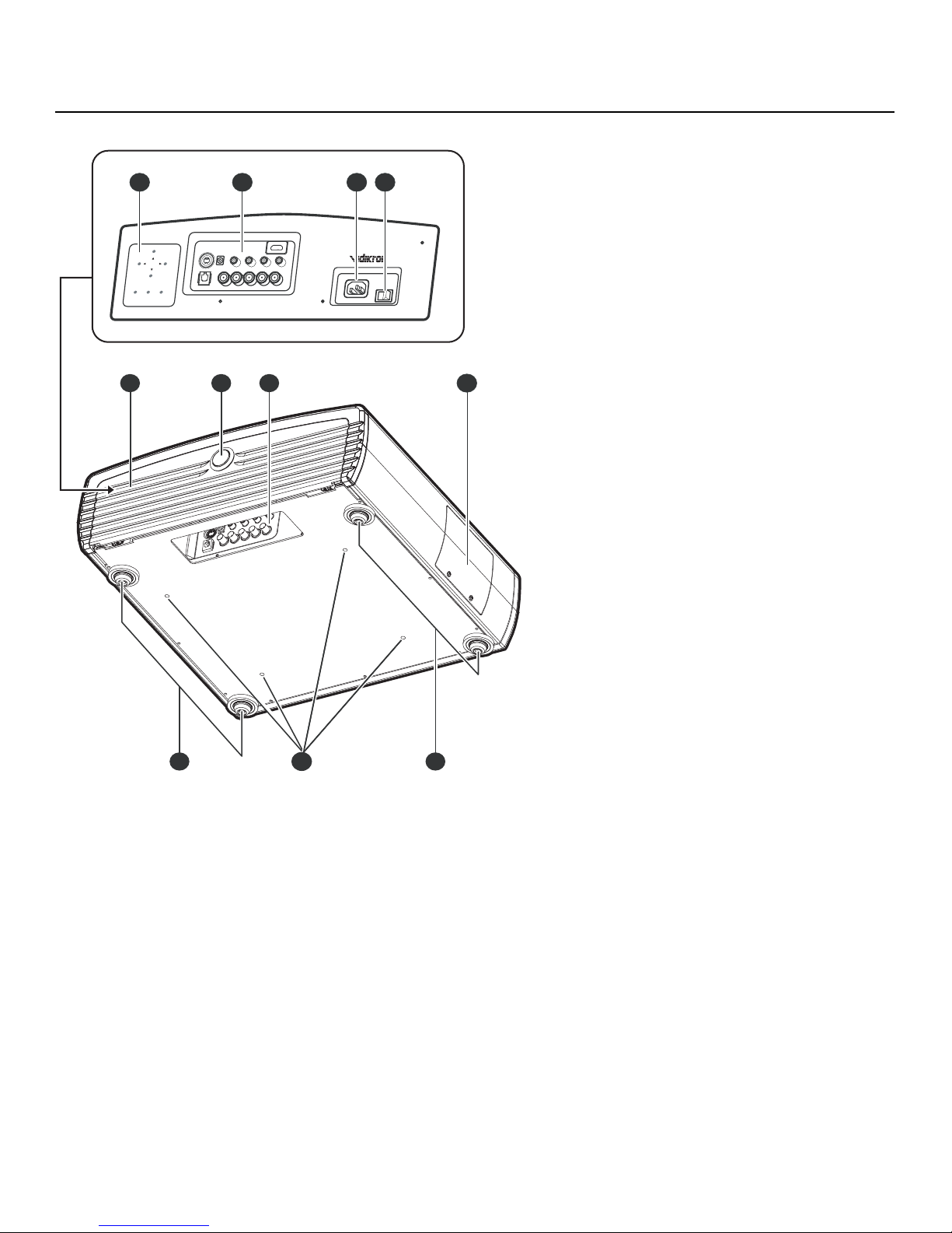
Figure 2-2. Vision 30 Rear/Bottom/Side View
8765
Y
IMINAR
L
1. CONNECTOR PANEL
Refer to Vision 30 Connector Panel, below.
2. POWER INPUT (100 to 240 VAC)
Connect the Vision 30 to power here.
3. MAIN POWER SWITCH
Disconnects or applies power to the Vision 30.
4. BUILT-IN KEYPAD
Refer to Built-In Keypad on page 9.
5. CABLE ACCESS DOOR
Open to access connectors.
6. DOOR RELEASE BUTTON
7. CABLE OPENING
Pass cables through this opening.
Vidikron Vision 30 Series Owner’s Operating Manual 7
Controls and Functions
8. LAMP MODULE COVER
Remove this cover to access the lamp compartment.
9. FRONT/REAR ADJUSTERS
Use these to adjust the projector height or projection angle.
10. CEILING MOUNT HOLES
Use these to attach the ceiling bracket to the projector.
2.2
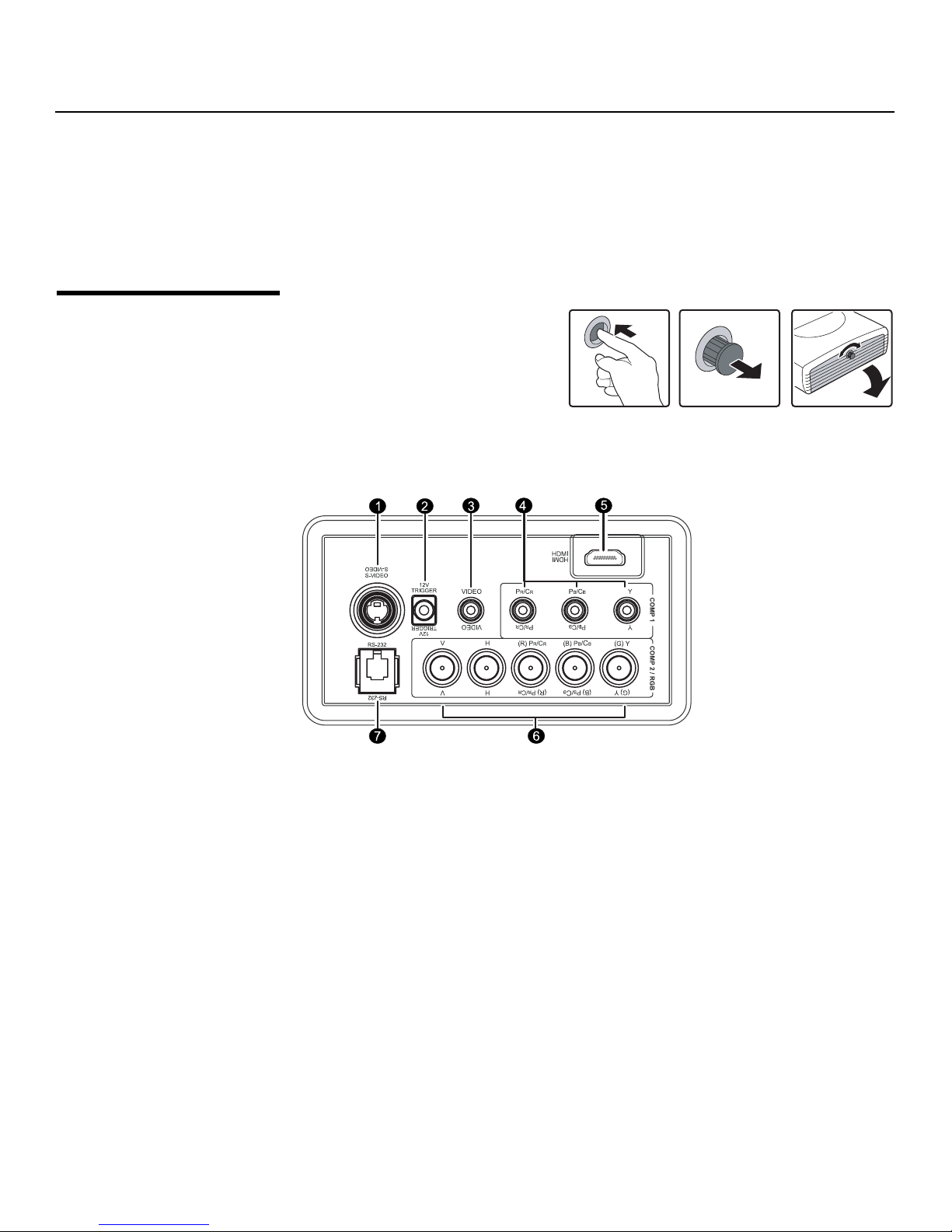
Vision 30 Connector Panel
To access the connector panel, press
the door release button so it pops out.
Turn the knob clockwise or
counter-clockwise and pull gently on it
to open the door.
Figure 2-3 shows the Vision 30 connector panel.
IMINAR
L
Y
PRE
Figure 2-3. Vision 30 Connector Panel
1. S-VIDEO
2. 12-VOLT (250 mA) TRIGGER OUTPUT (3.5-mm, mini phono jack)
3. COMPOSITE VIDEO INPUT
4. COMP 1 (RCA connectors)
A standard S-Video input for connecting a DVD player, satellite receiver or Super VHS
(S-VHS) VCR.
Connect this to a a retractable screen, screen mask or other 12-volt trigger-activated
equipment.
Standard composite video input for connecting a VCR, laser disc player or other
composite video source.
Standard Definition (480i/576i) Component (YPrPb) input. This is the input for
component video from sources such as DVD players.
8 Vidikron Vision 30 Series Owner’s Operating Manual

Controls and Functions
Tip
5. HDMI (Digital)
HDCP-compliant digital video input for connecting a DVD player or HD tuner with a DVI
or HDMI output.
6. COMP 2 / RGB
Five, BNC connectors for connecting either RGB or component (YPbPr) high-definition
television signals. (The Vision 30 automatically detects the signal format.)
7. RS-232 CONTROL PORT
A female, RJ-11 connector for interfacing with a PC or home theater automation/control
system.
To control the projector when signals from a remote
control cannot reach it, use the built-in keypad next to
the connector panel.
Because the built-in keypad has fewer keys than the
remote keypad, certain projector functions are
accessible only through the menu system rather than via
a direct key.
For best results, do not run your DVD player in progressive mode.
MEMORY
MEMORY
AUTO
Y
2.3
Built-In Keypad
IMINAR
L
PRE
POWER
MENU
/EXIT
POWER
AUTO
SOURCE
/ENTER
/EXIT
MENU
/ENTER
SOURCE
Vidikron Vision 30 Series Owner’s Operating Manual 9
Controls and Functions
2.4
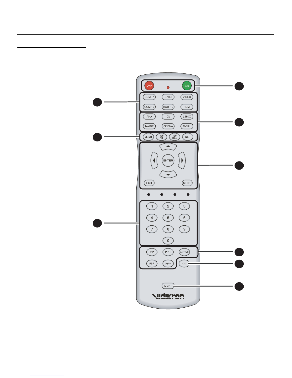
Vision 30 Remote Control
Figure 2-4 shows the Vision 30 remote control, and the paragraphs that follow describe its
functionality.
1
2
Y
4
3
5
IMINAR
L
6
PRE
Figure 2-4. Vision 30 Remote Control
7
8
9
10 Vidikron Vision 30 Series Owner’s Operating Manual

1. ON / OFF
Use these buttons to turn the projector on or off.
2. Source Selection Buttons:
COMP 1 (SD Component)
Press to select Component 1 (SD 480i/576i) video input as the source.
S-VID (S-Video)
Press to select the S-Video input as the source.
VIDEO
Press to select Composite video input as the source.
COMP 2 (HD Component)
Press to select Component 2 (HD 480p/576p/720p/1080i) video input as the source.
RGB HD
Press to select the Component 2 RGB input.
HDMI
Press to select the HDMI input.
Controls and Functions
Y
3. Aspect Ratio Selection Buttons
Use these buttons to select an aspect ratio directly, as follows:
ANA (Anamorphic)
For viewing 16:9 DVDs or HDTV programs in their native aspect ratio.
4X3 (Standard 4:3)
Scales the input signal to fit 4:3 display mode in the center of the screen.
L-BOX (Letterbox)
For viewing LaserDisc movies or non-anamorphic DVDs on a 4:3 screen.
I-WIDE (IntelliWide)
Enlarges a 4:3 image horizontally in a NON-linear fashion to fit 16:9 full screen display.
CINEMA
For viewing 2.35:1 source material.
C-FILL (Vision 30/CineWide and Vision 30ET/CineWide only)
Selects the Cinema Fill aspect ratio, used for viewing 16:9 source material on a 2.35:1
screen.
PRE
IMINAR
L
Vidikron Vision 30 Series Owner’s Operating Manual 11

Controls and Functions
4. Memory Preset Buttons:
MEM1
Press to recall settings for the current input from the “Custom 1” memory preset.
ISF NT
Press to recall settings for the current input from the “ISF Night” memory preset.
ISF DAY
Press to recall settings for the current input from the “ISF Day” memory preset.
DEF
Press to recall the factory-default settings for the current input.
5. Cursor Keys ( , , , )
Use these buttons to select items or settings, adjust settings or switch display patterns.
EXIT
Press to save menu item setting(s), exit the current menu and return to the previous one.
ENTER
Press to select a highlighted menu item or confirm a changed setting.
MENU
Press this button to show or hide the on-screen display (OSD) controls.
Y
6. 0 - 9
Use these keys to enter menu passcodes.
7. Picture-In-Picture (PIP) / Picture-By-Picture (PBP) Controls:
PIP
Press to activate PIP mode.
PIP+
Press to enlarge the PIP window.
PRE
ACTIVE
Press to switch to the active window in PIP or PBP mode.
PBP
Press to activate PBP mode.
PIP-
Press to shrink the size of the PIP window.
8. VAC
Not applicable to this model.
9. LIGHT
Press to illuminate the buttons.
IMINAR
L
12 Vidikron Vision 30 Series Owner’s Operating Manual
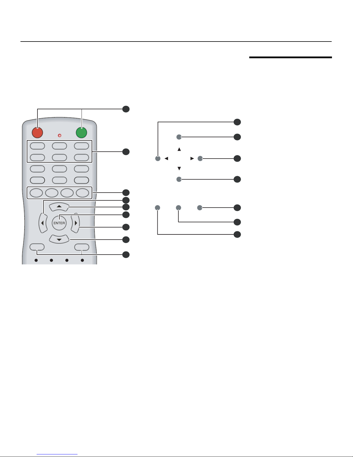
Controls and Functions
Figure 2-5 shows remote control buttons that are duplicated on the built-in keypad.
Some functions such as power ON/OFF are combined in one button on the built-in keypad;
however, the function is the same. This user manual describes the functions based on the
remote control.
7
ISF
DAY
ON
VIDEO
HDMI
L-BOX
C-FILL
DEF
MEMORY
Y
5
AUTO
2
1
POWER
MENU
/EXIT
SOURCE
/ENTER
OFF
COMP 1
COMP 2
ANA
I-WIDE
MEM1
ISF
NT
S-VID
RGB HD
4X3
CINEMA
2
5
3
IMINAR
4
EXIT
MENU
L
6
2.5
Remote Control/Built-In
Keypad Functional
Comparison
1
2
3
4
5
6
7
Figure 2-5. Remote Control/Built-In Keypad Functional Cross-Reference
PRE
Vidikron Vision 30 Series Owner’s Operating Manual 13

Controls and Functions
Notes:
Y
IMINAR
L
PRE
14 Vidikron Vision 30 Series Owner’s Operating Manual
 Loading...