

Vidikron Vision 15ET, Vision 15ET/CineWide Installation & Operation Manual

Digital Light Processing (DLP™) Projectors
Vision 15
Vision 15ET
Vision 15ET/CineWide™
15
VERSION 1.1
INSTALLATION/OPERATION MANUAL


TWO YEAR LIMITED WARRANTY
For Projectors, Video Processors and Controllers
Congratulations on your purchase of a Vidikron video product and welcome to the Vidikron family! With proper installation, setup
and care, you should enjoy many years of unparalleled video performance.
This is a LIMITED WARRANTY as defined in the Magnuson-Moss Warranty Act. Please read it carefully and retain it with your other
important documents.
WHAT IS COVERED UNDER THE TERMS OF THIS LIMITED WARRANTY:
SERVICE LABOR: Planar Systems, Inc. (“Planar”) will pay for service labor at an Authorized Service Center when needed as a result of
manufacturing defect for a period of two (2) years from the effective date of delivery to the end user (excluding the lamp).
PARTS (not including the lamp): Planar will provide new or rebuilt replacement parts for the parts that fail due to defects in
materials or workmanship for a period of two (2) years from the effective date of delivery to the end user. Such replacement parts
are then subsequently warranted for the remaining portion (if any) of the original warranty period.
PROJECTOR LAMP: Planar will pay for service labor at an Authorized Service Center when needed as a result of a manufacturing
defect for a period of six (6) months or 1000 hours, whichever comes first, from the effective date of delivery to the end user. In
addition, Planar will provide a new or rebuilt replacement lamp for the lamp that fails due to defects in materials or workmanship
for a period of six (6) months or 1000 hours, whichever comes first, from the effective date of delivery to the end user. Such
replacement lamps are then subsequently warranted for the remaining portion (if any) of the original warranty period.
WHAT IS NOT COVERED UNDER THE TERMS OF THIS LIMITED WARRANTY:
This Limited Warranty only covers failure due to defects in materials and workmanship that occur during normal use and does not
cover normal maintenance. This Limited Warranty does not cover cabinets or any appearance items; failure resulting from
accident, misuse, abuse, neglect, mishandling, misapplication, faulty or improper installation or setup adjustments; improper
maintenance, alteration, improper use of any input signal; damage due to lightning or power line surges, spikes and brownouts;
damage that occurs during shipping or transit; or damage that is attributed to acts of God. In the case of remote control units,
damage resulting from leaking, old, damaged or improper batteries is also excluded from coverage under this Limited Warranty.
CAUTION: THIS LIMITED WARRANTY ONLY COVERS VIDIKRON PRODUCTS PURCHASED FROM AUTHORIZED VIDIKRON DEALERS.
ALL OTHER PRODUCTS ARE SPECIFICALLY EXCLUDED FROM COVERAGE UNDER THIS WARRANTY. MOREOVER, DAMAGE
RESULTING DIRECTLY OR INDIRECTLY FROM IMPROPER INSTALLATION OR SETUP IS SPECIFICALLY EXCLUDED FROM COVERAGE
UNDER THIS LIMITED WARRANTY. IT IS IMPERATIVE THAT INSTALLATION AND SETUP WORK BE PERFORMED ONLY BY AN
AUTHORIZED VIDIKRON DEALER TO PROTECT YOUR RIGHTS UNDER THIS WARRANTY. THIS WILL ALSO ENSURE THAT YOU ENJOY
THE FINE PERFORMANCE OF WHICH YOUR VIDIKRON PRODUCT IS CAPABLE WHEN INSTALLED AND CALIBRATED BY AN
AUTHORIZED VIDIKRON DEALER.
RIGHTS, LIMITS AND EXCLUSIONS:
Planar limits its obligations under any implied warranties under state laws to a period not to exceed the warranty period. There are
no express warranties. Planar also excludes any obligation on its part for incidental or consequential damages related to the failure
of this product to function properly. Some states do not allow limitations on how long an implied warranty lasts, and some states
do not allow the exclusion or limitation of incidental or consequential damages. So the above limitations or exclusions may not
apply to you. This warranty gives you specific legal rights, and you may also have other rights that vary from state to state.
Vidikron Vision Model 15 Installation/Operation Manual iii

EFFECTIVE WARRANTY DATE:
This warranty begins on the effective date of delivery to the end user. For your convenience, keep the original bill of sale as
evidence of the purchase date.
IMPORTANT – WARRANTY REGISTRATION:
Please fill out and mail your warranty registration card. It is imperative that Planar knows how to reach you promptly if we should
discover a safety problem or product update for which you must be notified.
CONTACT AN AUTHORIZED SERVICE CENTER TO OBTAIN SERVICE:
Repairs made under the terms of this Limited Warranty covering your Vidikron video product will be performed at the location of
the product, during usual working hours, providing location of product is within normal operating distance from an Authorized
Vidikron Service Center. In some instances it may be necessary for the product to be returned to the Vidikron factory for repairs. If,
solely in Planar’s judgment, location of product to be repaired is beyond normal operating distance of the closest Authorized
Vidikron Service Center, or the repair requires the unit be returned to the Vidikron factory, it is the owner’s responsibility to arrange
for shipment of the product for repair. These arrangements must be made through the selling Vidikron Dealer. If this is not
possible, contact Planar directly for a Return Authorization number and shipping instructions. Planar will return product
transportation prepaid in the United States, unless no product defect is discovered. In that instance, shipping costs will be the
responsibility of the owner.
COPYRIGHT AND TRADEMARKS:
© Copyright 2008 Planar Systems, Inc. This document contains proprietary information protected by copyright, trademark and
other intellectual property laws. All rights are reserved. No part of this manual may be reproduced by any mechanical, electronic or
other means, in any form, without prior written permission of the manufacturer.
Trademarks and registered trademarks used in this document are the property of their respective owners.
Vidikron products are manufactured under one or more of the following patents: US. Patent 6755540 and Other Patents Pending.
iv Vidikron Vision Model 15 Installation/Operation Manual

ADDITIONAL INFORMATION:
To locate the name and address of the nearest Authorized Vidikron Service Center, or for additional information about this Limited
Warranty, please call or write:
PLANAR SYSTEMS, INC.
1195 NW Compton Drive
Beaverton, OR 97006-1992
Ph: (503) 748-5799
Fax: (503) 682-9441
Toll Free: (866) PLANAR1
PRODUCT INFORMATION
RETAIN FOR YOUR RECORDS
_________________________________________________________ ________________________________________
Model Purchased Date
____________________________________________________________________________________________________________
Serial Number
____________________________________________________________________________________________________________
Vidikron Authorized Dealer Name
____________________________________________________________________________________________________________
Address
____________________________________________ __________________ ________________________
City State/Province Postal Code
____________________________________________ _______________________________________________________
Phone Fax
Vidikron Vision Model 15 Installation/Operation Manual v

Important Safety Instructions
Thank you for your purchase of this quality Vidikron video projector! It has been designed to provide you with the quality of video
that is expected in a home theater. For the best performance, please read this manual carefully as it is your guide through the
menus and operation.
WAR NING
CAUTION
RISK OFELECTRIC SHOCK
DO NOTOPEN
TO REDUCE THE RISK OF ELECTRIC SHOCK
DO NOT REMOVE COVER (OR BACK)
NO USER SERVICEABLE PARTS INSIDE.
REFER SERVICING TO QUALIFIED
CAUTION:
SERVICE PERSONNEL.
1. Read these instructions.
2. Keep these instructions.
3. Heed all warnings.
4. Follow all instructions.
5. Do not use this apparatus near water.
This symbol is intended to alert the user to the presence of
uninsulated “dangerous voltage” within the product’s enclosure that
may be of sufficient magnitude to constitute a risk of electric shock.
This symbol is intended to alert the user to the presence of important
operating and maintenance (servicing) instructions in the literature
accompanying the appliance.
6. Clean only with a dry cloth.
7. Do not block any of the ventilation openings. Install in accordance with the manufacturer’s instructions.
8. Do not install near any heat sources such as radiators, heat registers, stoves, or other apparatus (including amplifiers) that
produce heat.
9. Do not defeat the safety purpose of the polarized or grounding type plug. A polarized plug has two blades with one wider
than the other. A grounding type plug has two blades and a third grounding prong. The wide blade or the third prong is
provided for your safety. When the provided plug does not fit into your outlet, consult an electrician for the replacement of the
obsolete outlet.
10. Protect the power cord from being walked on or pinched particularly at plugs, convenience receptacles and the point where
they exit from the apparatus.
11. Only use the attachments/accessories specified by the manufacturer.
12. Use only with a cart, stand, tripod, bracket or table specified by the manufacturer or sold with the apparatus. When
a cart is used, use caution when moving the cart/apparatus to avoid injury from tip-over.
13. Unplug this apparatus during lightning storms or when unused for long periods of time.
14. Refer all servicing to qualified service personnel. Servicing is required when the apparatus has been damaged in
any way, such as power supply cord or plug is damaged, liquid has been spilled or objects have fallen into the apparatus, the
apparatus has been exposed to rain or moisture, does not operate normally, or has been dropped.
15. The +12V trigger only outputs 12Vdc signal for triggering. Do not connect to any other power input or output. This could
cause damage to this unit.
16. Keep the packing material in case the equipment should ever need to be shipped.
17. The lamp becomes extremely hot during operation. Allow the projector to cool down for approximately 45 minutes prior to
removing the lamp assembly for replacement.
vi Vidikron Vision Model 15 Installation/Operation Manual

18. Do not operate lamps beyond the rated lamp life. Excessive operation of lamps beyond rated life could cause them to explode
in rare occasions.
19. Never look directly into the lens when the lamp is on.
Compliance Information
DECLARATION OF CONFORMITY:
Manufacturer’s Name: Planar Systems, Inc.
Manufacturer’s Address: 1195 NW Compton Drive, Beaverton, OR 97006-1992
hereby declares that the products Model Numbers:
Vision 15, Vision 15ET and Vision 15ET/CineWide
conform with the provisions of:
Council Directive 2004/108/EC on Electromagnetic Compatibility;
EN 55022 “Limits and methods of measurements of radio interference characteristics of information technology equipment” 1998;
EN 55024 “Limits and methods of measurements of immunity characteristics of information technology equipment” 1998;
Including:
• EN 61000-4-2 “Electromagnetic compatibility (EMC) Part 4: Testing and measurement techniques Section 2: Electrostatic
discharge immunity test”
• EN 61000-4-3 “Electromagnetic compatibility (EMC) Part 4: Testing and measurement techniques Section 3: Radiated,
Radio-Frequency, Electromagnetic Field Immunity Test”
• EN 61000-4-4 “Electromagnetic compatibility (EMC) Part 4: Testing and measurement techniques Section 4: Electrical fast
transient/burst immunity test”
• EN 61000-4-5 "Electromagnetic compatibility (EMC) Part 4: Testing and measurement techniques Section 5: Surge immunity
test"
• EN 61000-4-6 "Electromagnetic compatibility (EMC) Part 4: Testing and measurement techniques Section 6: Conducted
disturbances induced by radio-frequency fields immunity test"
• EN 61000-4-8 "Electromagnetic compatibility (EMC) Part 4: Testing and measurement techniques Section 8: Conducted
disturbances induced by power frequency magnetic fields immunity test"
• EN 61000-4-11 "Electromagnetic compatibility (EMC) Part 4: Testing and measurement techniques Section 11: Voltage dips,
short interruptions and voltage variations immunity tests"
And:
• EN 61000-3-2 "Electromagnetic compatibility (EMC) Part 3, Section 2: Limits for harmonic current emissions (equipment input
current up to and including 16 A per phase)" 2000;
• EN 61000-3-3 "Electromagnetic compatibility (EMC) Part 3, Section 3: Limitations of voltage changes, voltage fluctuations and
flicker in public low-voltage supply systems, for equipment with rated current up to and including 16 A and not subject to
conditional connection" 1995;
Council Directive 2006/95/EC and amended by M1 and C1 on Low Voltage Equipment Safety;
EN 60950 “Safety of information technology equipment, including electrical business equipment”
Vidikron Vision Model 15 Installation/Operation Manual vii

The Technical Construction file required by this Directive is maintained at the corporate headquarters of Planar Systems, Inc., 1195
NW Compton Drive, Beaverton, OR 97006-1992.
Date of Declaration: January 2008
FCC PART 15:
NOTE: This equipment has been tested and found to comply with the limits for a Class B digital device, pursuant to Part 15 of the
FCC Rules. These limits are designed to provide reasonable protection against harmful interference in a residential installation.
This equipment generates, uses and can radiate radio frequency energy and, if not installed and used in accordance with the
instructions, may cause harmful interference to radio communications. However, there is no guarantee that interference will not
occur in a particular installation. If this equipment does cause harmful interference to radio or television reception, which can be
determined by turning the equipment off and on, the user is encouraged to try to correct the interference by one or more of the
following measures:
• Reorient or relocate the receiving antenna.
• Increase the separation between the equipment and receiver.
• Connect the equipment into an outlet on a circuit different from that to which the receiver is connected.
• Consult the dealer or an experienced radio/TV technician for help.
INDUSTRY CANADA (ICES-003):
This Class B digital apparatus complies with Canadian ICES-003.
Cet appareil numérique de la classe B est conforme à la norme NMB-003 du Canada.
IMPORTANT RECYCLE INSTRUCTIONS
Lamp(s) inside this product contain mercury. This product may contain other electronic waste that can be hazardous if
not disposed of properly. Recycle or dispose in accordance with local, state, or federal Laws.
For more information, contact the Electronic Industries Alliance at WWW.EIAE.ORG.
For lamp specific disposal information check WWW.LAMPRECYCLE.ORG.
DISPOSAL OF OLD ELECTRICAL AND ELECTRONIC EQUIPMENT (Applicable throughout the European Union and other
European countries with separate collection programs)
This symbol found on your product or on its packaging, indicates that this product should not be treated as
household waste when you wish to dispose of it. Instead, it should be handed over to an applicable collection
point for the recycling of electrical and electronic equipment. By ensuring this product is disposed of correctly,
you will help prevent potential negative consequences to the environment and human health, which could
otherwise be caused by inappropriate disposal of this product. The recycling of materials will help to conserve
natural resources. This symbol is only valid in the European Union. If you wish to discard this product, please
contact your local authorities or dealer and ask for the correct method of disposal.
viii Vidikron Vision Model 15 Installation/Operation Manual

1Table of Contents
TWO YEAR LIMITED WARRANTY ............................................................................................. iii
Important Safety Instructions ................................................................................................. vi
Compliance Information .........................................................................................................vii
1. Introduction ........................................................................................................................ 1
About This Manual ............................................................................................................................................ 1
If You Have Comments About This Manual... .................................................................................. 1
Textual and Graphic Conventions ....................................................................................................... 1
Using This Manual ............................................................................................................................................. 2
Description, Features and Benefits ............................................................................................................. 3
Key Features and Benefits....................................................................................................................... 4
Parts List ........................................................................................................................................................ 4
2. Controls and Functions ...................................................................................................... 5
Vision 15 at a Glance ........................................................................................................................................ 5
Vision 15 Rear Panel ......................................................................................................................................... 6
Vision 15 Remote Control ............................................................................................................................... 8
3. Installation ........................................................................................................................ 11
Remote Control ................................................................................................................................................ 11
Notes on Batteries ................................................................................................................................... 11
Notes on Remote Control Operation................................................................................................ 12
Quick Setup ....................................................................................................................................................... 13
Installation Considerations ..........................................................................................................................14
Installation Type.......................................................................................................................................14
Ambient Light ........................................................................................................................................... 14
Throw Distance......................................................................................................................................... 15
Vertical and Horizontal Position ......................................................................................................... 16
Vertical and Horizontal Lens Shift......................................................................................................17
Folded Optics ............................................................................................................................................19
Other Considerations ............................................................................................................................. 20
Installing the Optional CineWide Lens Base Plate ...............................................................................20
Mounting the Vision 15 ................................................................................................................................. 22
Floor Mounting (Upright) .....................................................................................................................22
Ceiling Mounting (Inverted) ................................................................................................................ 22
Adjusting the Projector Height or Projection Angle...................................................................22
Vidikron Vision Model 15 Installation/Operation Manual ix

Table of Contents
Connections to the Vision 15 ...................................................................................................................... 23
Connector Panel Access ........................................................................................................................23
Connecting Source Components to the Vision 15 ...................................................................... 23
RS-232 Controller Connection ............................................................................................................ 28
Connecting 12-Volt Trigger Output to External Theater Equipment ................................... 29
Turning on the Power ....................................................................................................................................29
Changing the OSD Language ..................................................................................................................... 30
Adjusting the Picture Orientation ............................................................................................................. 30
Primary Lens Adjustments ...........................................................................................................................31
Focus and Zoom.......................................................................................................................................31
Shift .............................................................................................................................................................. 32
Installing and Adjusting the CineWide Anamorphic Lens ................................................................ 33
4. Operation .......................................................................................................................... 35
Using the On-Screen Menus ........................................................................................................................35
Main Menu .................................................................................................................................................36
Source Select .............................................................................................................................................37
Picture Adjust ............................................................................................................................................37
Aspect Ratio ............................................................................................................................................... 42
Installation..................................................................................................................................................45
Information ................................................................................................................................................48
Setup ............................................................................................................................................................49
ISF .................................................................................................................................................................. 50
5. Maintenance and Troubleshooting ................................................................................ 53
Cleaning the Projector ...................................................................................................................................53
Cleaning the Lens ............................................................................................................................................ 53
Cleaning the Intake and Exhaust Vents ................................................................................................... 54
Lamp Maintenance .........................................................................................................................................55
Lamp Cautions .................................................................................................................................................. 55
Lamp Replacement .........................................................................................................................................56
Troubleshooting Tips .....................................................................................................................................57
6. Serial Communications ....................................................................................................59
RS-232 Connection and Port Configuration ..........................................................................................59
Serial Command Syntax ................................................................................................................................59
x Vidikron Vision Model 15 Installation/Operation Manual

Table of Contents
7. Specifications .................................................................................................................... 61
Vision 15 Specifications .................................................................................................................................61
Vision 15 Dimensions .....................................................................................................................................63
Vision 15ET Dimensions ................................................................................................................................ 64
Computer Signal Compatibility ..................................................................................................................65
Video Signal Compatibility .......................................................................................................................... 66
Vidikron Vision Model 15 Installation/Operation Manual xi

Table of Contents
Notes:
xii Vidikron Vision Model 15 Installation/Operation Manual

1List of Figures
2-1. Vision 15 Front/Side/Top View . . . . . . . . . . . . . . . . . . . . . . . . . . . . . . . . . . . . . . . . . . . . . . . . . . . . . . . . . . 5
2-2. Vision 15 Rear Panel . . . . . . . . . . . . . . . . . . . . . . . . . . . . . . . . . . . . . . . . . . . . . . . . . . . . . . . . . . . . . . . . . . . . 6
2-3. Vision 15 Remote Control . . . . . . . . . . . . . . . . . . . . . . . . . . . . . . . . . . . . . . . . . . . . . . . . . . . . . . . . . . . . . . . 8
3-1. Available Range of the Remote Control . . . . . . . . . . . . . . . . . . . . . . . . . . . . . . . . . . . . . . . . . . . . . . . . . 12
3-2. Estimating Throw Distance . . . . . . . . . . . . . . . . . . . . . . . . . . . . . . . . . . . . . . . . . . . . . . . . . . . . . . . . . . . . . 15
3-3. Projector Placement . . . . . . . . . . . . . . . . . . . . . . . . . . . . . . . . . . . . . . . . . . . . . . . . . . . . . . . . . . . . . . . . . . . 16
3-4. Vertical Lens Shift (Example only). . . . . . . . . . . . . . . . . . . . . . . . . . . . . . . . . . . . . . . . . . . . . . . . . . . . . . . 17
3-5. Horizontal Lens Shift (Example only). . . . . . . . . . . . . . . . . . . . . . . . . . . . . . . . . . . . . . . . . . . . . . . . . . . . 18
3-6. Folded Optics. . . . . . . . . . . . . . . . . . . . . . . . . . . . . . . . . . . . . . . . . . . . . . . . . . . . . . . . . . . . . . . . . . . . . . . . . . 19
3-7. Vision 15ET/CineWide with Lens Base Plate and Ceiling Mounting Plate - Exploded View . 21
3-8. Adjusting the Feet . . . . . . . . . . . . . . . . . . . . . . . . . . . . . . . . . . . . . . . . . . . . . . . . . . . . . . . . . . . . . . . . . . . . . 22
3-9. HDMI/DVI Source Connections . . . . . . . . . . . . . . . . . . . . . . . . . . . . . . . . . . . . . . . . . . . . . . . . . . . . . . . . . 24
3-10. RGB Connections . . . . . . . . . . . . . . . . . . . . . . . . . . . . . . . . . . . . . . . . . . . . . . . . . . . . . . . . . . . . . . . . . . . . . 25
3-11. Component Video Connections . . . . . . . . . . . . . . . . . . . . . . . . . . . . . . . . . . . . . . . . . . . . . . . . . . . . . . . 26
3-12. Composite and S-Video Connections. . . . . . . . . . . . . . . . . . . . . . . . . . . . . . . . . . . . . . . . . . . . . . . . . . 27
3-13. RS-232 Control System Connection . . . . . . . . . . . . . . . . . . . . . . . . . . . . . . . . . . . . . . . . . . . . . . . . . . . 28
3-14. Connecting the 12-Volt Trigger Output to Other Equipment . . . . . . . . . . . . . . . . . . . . . . . . . . . 29
3-15. Focus and Zoom Controls. . . . . . . . . . . . . . . . . . . . . . . . . . . . . . . . . . . . . . . . . . . . . . . . . . . . . . . . . . . . . 31
3-16. Vertical and Horizontal Lens Shift Controls . . . . . . . . . . . . . . . . . . . . . . . . . . . . . . . . . . . . . . . . . . . . 32
3-17. Anamorphic Lens Mounting Assembly - Exploded View . . . . . . . . . . . . . . . . . . . . . . . . . . . . . . . . 33
4-1. Vision 15 OSD Menu Structure . . . . . . . . . . . . . . . . . . . . . . . . . . . . . . . . . . . . . . . . . . . . . . . . . . . . . . . . . 36
4-2. Typical PLUGE Pattern for Adjusting Brightness . . . . . . . . . . . . . . . . . . . . . . . . . . . . . . . . . . . . . . . . . 38
4-3. Typical Gray Bar Pattern for Adjusting Contrast . . . . . . . . . . . . . . . . . . . . . . . . . . . . . . . . . . . . . . . . . 38
4-4. Typical Color Bar Pattern for Adjusting Color Saturation and Tint . . . . . . . . . . . . . . . . . . . . . . . . 39
4-5. Typical Test Pattern for Adjusting Sharpness . . . . . . . . . . . . . . . . . . . . . . . . . . . . . . . . . . . . . . . . . . . . 40
4-6. Keystone Correction . . . . . . . . . . . . . . . . . . . . . . . . . . . . . . . . . . . . . . . . . . . . . . . . . . . . . . . . . . . . . . . . . . . 46
4-7. Overscan Examples . . . . . . . . . . . . . . . . . . . . . . . . . . . . . . . . . . . . . . . . . . . . . . . . . . . . . . . . . . . . . . . . . . . . 47
7-1. Vision 15 Dimensions . . . . . . . . . . . . . . . . . . . . . . . . . . . . . . . . . . . . . . . . . . . . . . . . . . . . . . . . . . . . . . . . . . 63
7-2. Vision 15ET Dimensions . . . . . . . . . . . . . . . . . . . . . . . . . . . . . . . . . . . . . . . . . . . . . . . . . . . . . . . . . . . . . . . . 64
Vidikron Vision Model 15 Installation/Operation Manual xiii

List of Figures
Notes:
xiv Vidikron Vision Model 15 Installation/Operation Manual

1Introduction
Note
This manual describes how to install, set up and operate a Vidikron Vision 15 Series Digital
Light Processing (DLP™) Projector. This product family consists of three models:
• Vision 15
• Vision 15ET (Extended-Throw)
• Vision 15ET/CineWide
Throughout this manual, all three projectors are referred to collectively as the “Vision 15.”
The information in this manual applies to all three projectors except where otherwise
indicated.
Vidikron has prepared this manual to help home theater installers and end users get the
most out of the Vision 15.
Vidikron has made every effort to ensure that this manual is accurate as of the date it was
printed. However, because of ongoing product improvements and customer feedback, it
may require updating from time to time. You can always find the latest version of this and
other Vidikron product manuals on-line, at www.Vidikron.com.
Vidikron welcomes your comments about this manual. Send them to info@Vidikron.com.
Text Conventions: The following conventions are used in this manual, in order to clarify the
information and instructions provided:
• Remote and built-in keypad button identifiers are set in upper-case bold type; for
example, “Press EXIT to return to the previous menu.”
• Computer input (commands you type) and output (responses that appear on-screen) is
shown in monospace (fixed-width) type; for example: “To change the aspect ratio to
Letterbox, type RRD02.”
• All keys with functional names are initial-capped, set in bold type and enclosed in angle
brackets. These keys are the following: <Enter>, <Spacebar>, <Control>,
<Esc> and <Tab>.
• <Enter> indicates that you may press either the RETURN or ENTER key on your keyboard
if it has both keys.
1.1
About This Manual
If You Have Comments About
This Manual...
Textual and Graphic
Conventions
In addition to these conventions, underlining, boldface and/or italics are occasionally used to
highlight important information, as in this example:
A carriage return must be used after each command or string.
Vidikron Vision Model 15 Installation/Operation Manual 1

Introduction
Note
Caution
WARNING
DANGER!
Graphic Conventions: These symbols appear in numerous places throughout the manual,
to emphasize points that you must keep in mind to avoid problems with your equipment or
injury:
TIPS highlight time-saving short cuts and helpful guidelines for using
Tip
certain features.
NOTES emphasize text with unusual importance or special significance.
They also provide supplemental information.
CAUTIONS alert users that a given action or omitted action can degrade
performance or cause a malfunction.
WARNINGS appear when a given action or omitted action can result in
damage to the equipment, or possible non-fatal injury to the user.
DANGER appears when a given action can cause severe injury or death.
1.2
Using This Manual
Use the following table to locate the specific information you need in this manual.
If you need... ... Turn to page:
Information about obtaining service iv
General information about the Vision Model 15 Series DLP
Projectors
Installation instructions 11
First-time configuration instructions 30
Advanced configuration instructions 49
Troubleshooting tips 57
Specifications for the Vision Model 15 Series DLP Projectors 61
3
2 Vidikron Vision Model 15 Installation/Operation Manual

Introduction
Note
The Vidikron Vision Model 15 Series DLP Projectors combines a highly efficient optical light
engine with broad installation and integration options.
Vidikron has implemented a host of advancements into the projector’s light engine to take
full advantage of its widescreen, high-definition Digital Micromirror Device (DMD™) chip. The
Vision 15 features Enhanced GEN 3™ technology to produce deeper blacks, greater contrast
ratio and brightness, and richly saturated colors.
Among the Vision 15’s features are a sophisticated color-balancing system that results in the
industry’s best gray scale tracking, and far surpasses the capabilities of CRT projectors.
Accurate gray scale reproduction is vital to vibrant, true-to-life color reproduction, as well as
superior black level and white level performance. Vidikron’s acclaimed Imagix™ video
processing and scaling assure pristine video imagery, while the Vision 15’s generous light
output capability is powerful enough to handle screens as large as 96 inches wide with ease.
The Vision 15 features a 16:9 aspect ratio resolution of 1280 x 720. It provides an HDMI input
for pure digital video signal transmission. In addition, the projector’s broad lens shift
capability, variable throw distance, and electronic horizontal and vertical keystone correction
allow for flexible placement within virtually any theater environment. Discrete IR and/or
serial control makes it simple to partner the Vision 15 with other audio/video components
and automated control systems for a truly high-end, home cinema system.
For uncompromising widescreen reproduction of movies originally filmed in the “scope”
(2.35:1) format, the Vision 15 can be equipped with Vidikron’s patent-pending CineWide™
technology, a combination of software, electronics and high-quality anamorphic optics.
CineWide maintains constant vertical height on the screen just as in a movie theater. When a
viewer transitions from 1.78:1 (16:9) program material to 2.35:1, the image simply gets wider
while full height is maintained.
1.3
Description, Features and
Benefits
CineWide requires the use of a 2.35:1 or similar aspect ratio superwide format
screen.
Vidikron Vision Model 15 Installation/Operation Manual 3

Introduction
➤
➤
Key Features and Benefits The Vision 15 offers these key features and benefits:
• Native Resolution: 1280 x 720
• High-performance Digital Light Processing (DLP™) engine
• HDMI Input with High-bandwidth Digital Content Protection (HDCP)
•HDTV Compatible
• Brilliant Color™ provides enhanced primary and secondary color processing for more
lifelike images
Parts List Your Vision 15 is shipped with the following items. If any items are missing or damaged,
please contact your Vidikron dealer or Vidikron Customer Service at (888) 4VIDIKRON.
• Vision 15 DLP Projector
•Remote Control Unit and two (2), AAA-size batteries
• AC Power Cord (by country)
•HDMI to HDMI Cable
• Serial Communication Cable (D-sub 9-pin female to Mini-DIN 9-pin male),
5.9 in. (15 cm)
• Warranty information and registration card
• Vidikron Vision Model 15 Installation/Operation Manual (this document)
Optional Accessories:
• CineWide™ technology (fixed, secondary anamorphic lens)
• Ceiling mount kit (part number 956-0256-00)
4 Vidikron Vision Model 15 Installation/Operation Manual
2Controls and Functions
Figure 2-1 shows the locations of key Vision 15 components.
1
11
10
9
2.1
Vision 15 at a Glance
2
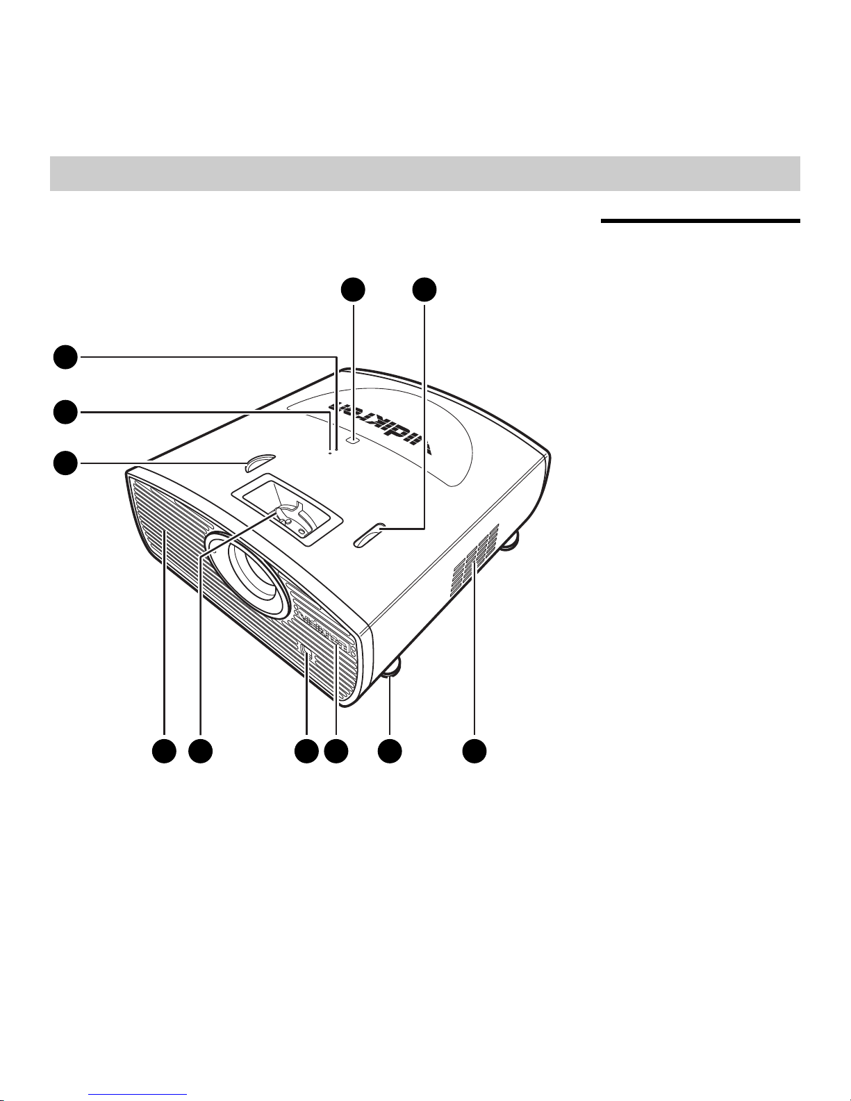
Figure 2-1. Vision 15 Front/Side/Top View
1. TOP IR SENSOR
2. VERTICAL LENS SHIFT DIAL
Shifts the image up or down.
3. INTAKE VENT
4. ADJUSTABLE FEET
Use to adjust the height or projection angle.
5. VIDIKRON LOGO
The logo can be rotated to match the projector orientation: inverted (ceiling-mounted)
or upright. To rotate the logo, grip it at the sides, pull it away from the projector and
rotate it 180 degrees.
Vidikron Vision Model 15 Installation/Operation Manual 5
345678
Controls and Functions
15
15
8
5 63 4
21
7
6. FRONT IR SENSOR
7. ZOOM/FOCUS RING
Use this to change the projected image size or focus the image.
8. EXHAUST VENT
9. HORIZONTAL LENS SHIFT DIAL
Shifts the image left or right.
10. TEMPERATURE INDICATOR
Flashes blue when the projector is overheated.
11. POWER/STANDBY INDICATOR
Indicates power status as follows:
• Lights solid blue when the projector is in standby mode
• Off during normal operation
• Flashes blue after the projector is turned off to indicate that the lamp is cooling down
2.2
Vision 15 Rear Panel
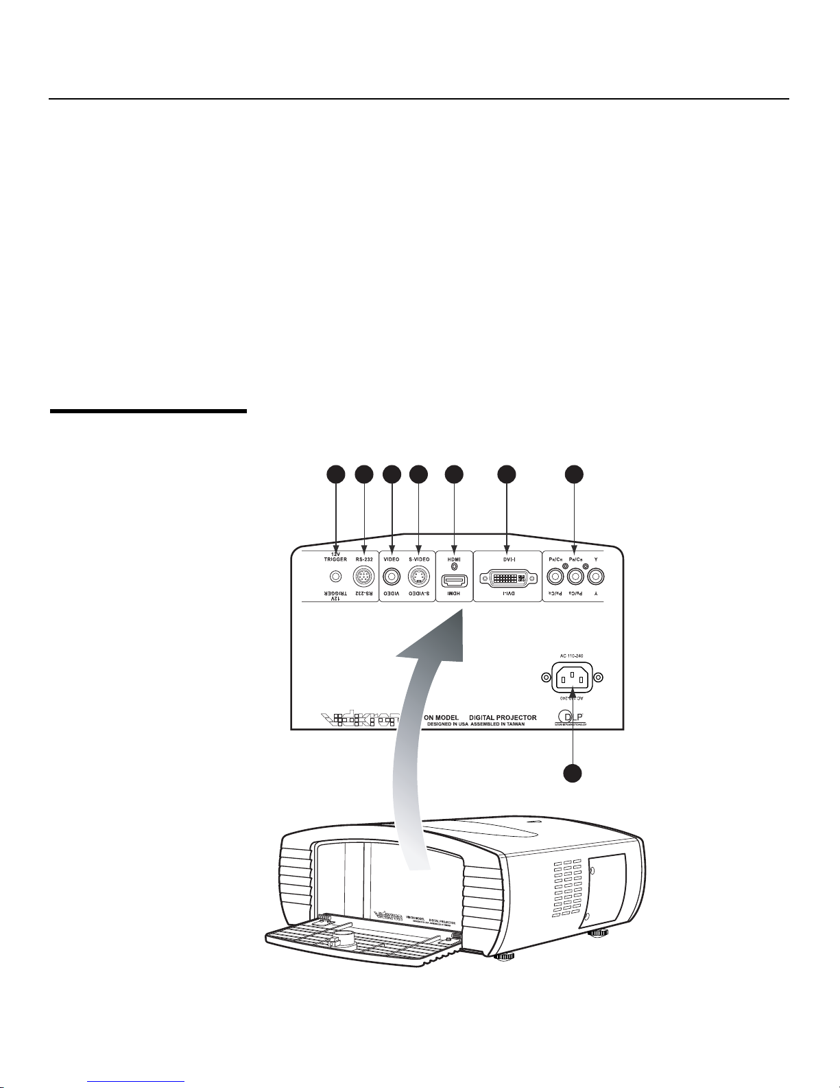
Figure 2-2 shows the Vision 15 rear panel.
Figure 2-2. Vision 15 Rear Panel
6 Vidikron Vision Model 15 Installation/Operation Manual

1. 12-VOLT (250 mA) TRIGGER OUTPUT (3.5-mm mini phono jack; Tip = +12V; Sleeve =
Tip
Ground)
Connection for a retractable screen, screen mask or other, 12-volt trigger-activated
device.
2. RS-232 CONTROL PORT
A female, 9-pin mini-DIN connector for interfacing with a PC or home theater
automation/control system.
3. COMPOSITE VIDEO INPUT
Standard composite video input for connecting a VCR, laser disc player or other
composite video source.
4. S-VIDEO
A standard S-Video input for connecting a DVD player, satellite receiver or Super VHS
(S-VHS) VCR.
5. HDMI
HDCP-compliant digital video input for connecting a DVD player or HD tuner with a DVI
or HDMI output.
6. DVI-I (Analog/Digital)
Accepts either an HDCP-compliant, digital video input (DVI-D) or an RGB PC signal from a
personal computer (DVI-A).
7. COMPONENT VIDEO (RCA connectors)
Standard- or high-definition (480i/480p/576i/576p/720p/1080i/1080p) Component
(YPrPb) input for connecting a DVD/HD-DVD/BD player, HD set-top box or other SD/HD
source.
Controls and Functions
For best results, do not run your DVD player in progressive mode.
8. POWER INPUT (100 to 240 VAC)
Connect the Vision 15 to power here.
Vidikron Vision Model 15 Installation/Operation Manual 7
Controls and Functions
2.3
Vision 15 Remote Control
Figure 2-3 shows the Vision 15 remote control, and the paragraphs that follow describe its
functionality.
1
OFF
COMP
SOURCE
S-VID
ON
2
VIDEO
3
11
12
DVI-A
16:9
I-WIDE
CUST
DVI-D
ASPECT
4:3
CINEMA
MEMORY
ISFNTISF
DAY
HDMI
L-BOX
I-WIDE
2.35
DEF
4
5
6
13
7
14
EXIT
MENU
8
2
5
0
LIGHT
15
1
4
789
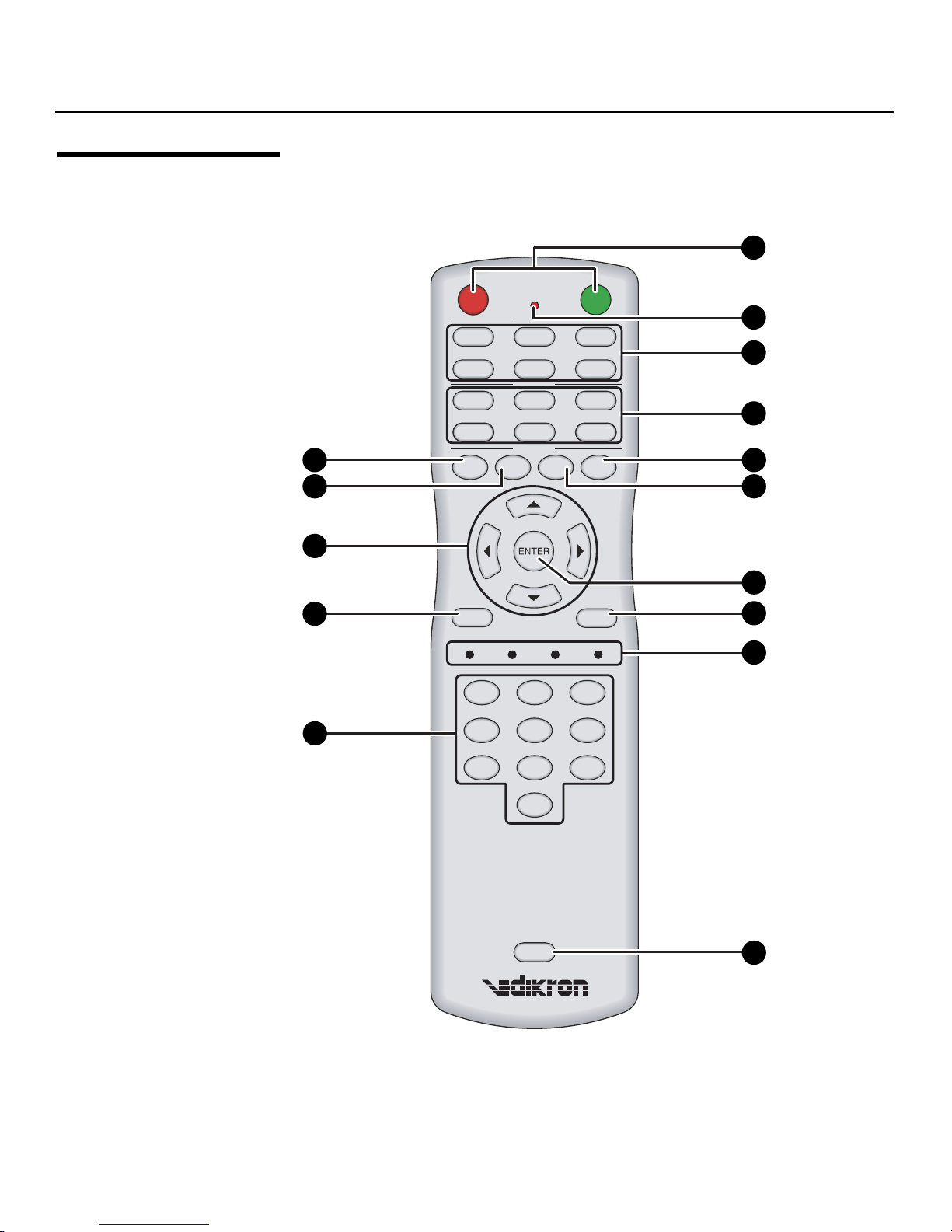
Figure 2-3. Vision 15 Remote Control
9
3
6
10
8 Vidikron Vision Model 15 Installation/Operation Manual

1. ON / OFF
Press to turn the projector on or off.
2. IR OUTPUT INDICATOR
Lights when a button is pressed to indicate that an IR signal is being transmitted.
3. Source Selection Buttons:
VIDEO
Press to switch to the Composite video input.
S-VIDEO
Press to switch to the S-Video input.
COMP
Press to switch to the Component (480i/480p/576i/576p/720p/1080i/1080p) video
input.
DVI-A
Press to switch to the DVI-A input.
DVI-D
Press to switch to the DVI-D input.
HDMI
Press to switch to the HDMI input.
4. Aspect Ratio Selection Buttons
Use these buttons to select an aspect ratio directly, as follows:
16:9
For viewing 16:9 DVDs or HDTV programs in their native aspect ratio.
4:3
Scales the input signal to fit 4:3 display mode in the center of the screen.
LETBOX (Letterbox)
For viewing LaserDisc movies or non-anamorphic DVDs on a 16:9 screen.
I-WIDE (IntelliWide)
Enlarges a 4:3 image horizontally in a NON-linear fashion to fit 16:9 full screen display.
CINEMA
For viewing 2.35:1 source material.
I-WIDE (IntelliWide 2.35 – Vision 15ET/CineWide only)
Selects the IntelliWide 2.35 aspect ratio, used for viewing 16:9 source material on a 2.35:1
screen.
Controls and Functions
5. DEF
Press to restore factory-default settings for the current source.
6. ISF DAY
Press to recall settings for the current input from the “ISF Day” memory preset.
7. ENTER
Press to select a highlighted menu item or confirm a changed setting.
Vidikron Vision Model 15 Installation/Operation Manual 9

Controls and Functions
8. MENU
Press this button to access the on-screen display (OSD) controls.
9. Not used.
10. LIGHT
Press this button to illuminate the buttons.
11. CUST
Press to recall settings for the current input from the “Custom” memory preset.
12. ISF NT
Press to recall settings for the current input from the “ISF Night” memory preset.
13. Cursor Keys ( , , , )
Use these buttons to select items or settings, adjust settings or switch display patterns.
14. EXIT
Press this button to exit the current menu and return to the previous one.
15. NUMBER KEYS
Use these buttons to enter menu passcodes.
10 Vidikron Vision Model 15 Installation/Operation Manual
3Installation
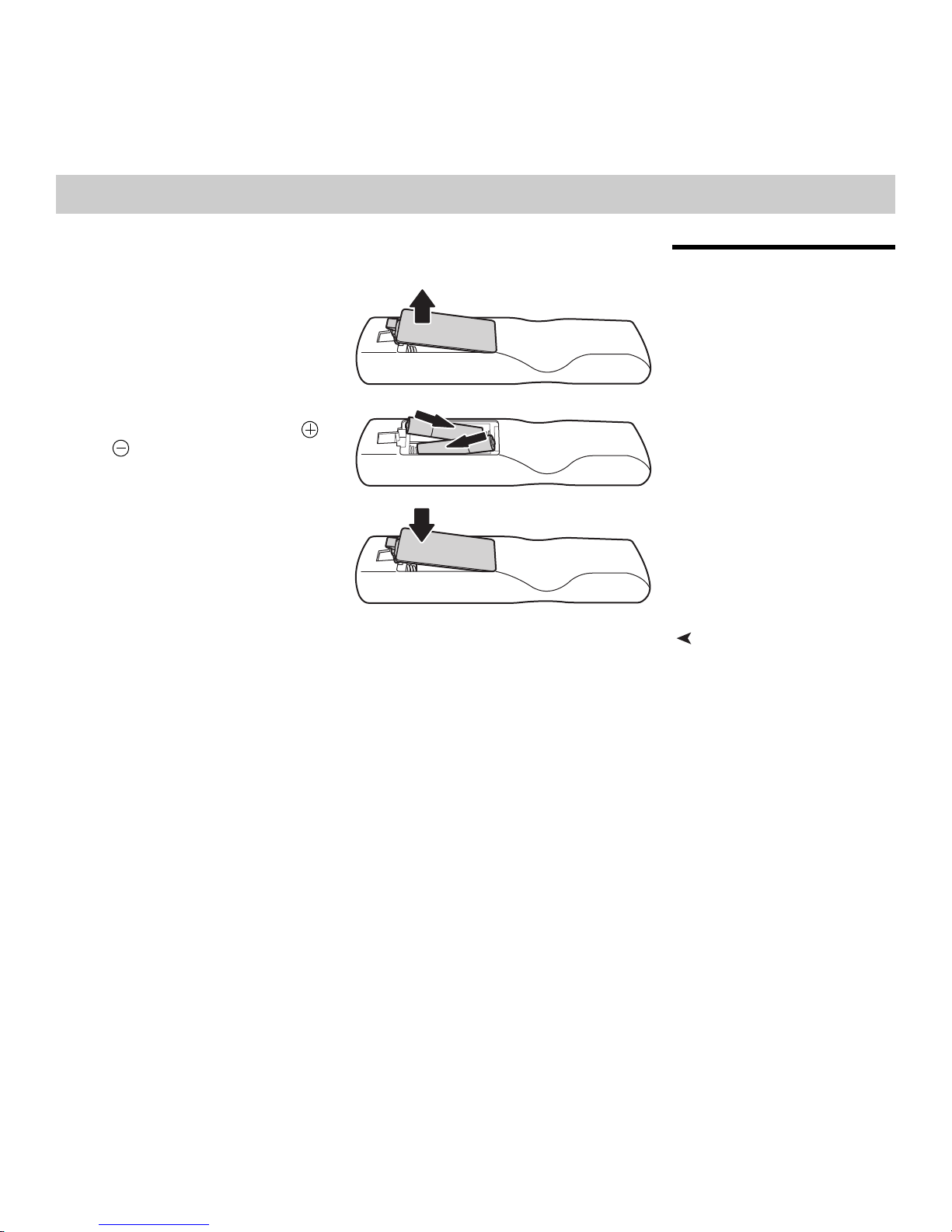
To install batteries in the remote control:
1. Press down the tab on the cover and
pull the cover in the direction of the
arrow.
2. Insert the included batteries. Ensure that
the polarities correctly match the
and markings inside the battery
compartment.
3. Insert the lower tab of the cover into the
opening, and press down the cover until
it clicks in place.
• Do not mix an old battery with a new one or different types of batteries.
• If you will not use the remote control for a long time, remove the batteries to avoid
damage from battery leakage.
3.1
Remote Control
Notes on Batteries• Make sure that the battery polarities are correct when installing the batteries.
Vidikron Vision Model 15 Installation/Operation Manual 11
 Loading...