

Vidikron Vision 150, Vision 140/CineWide with AutoScope, Vision 150/CineWide with AutoScope Installation & Operation Manual

1080p LightAmp™ Digital Projector
Vision 140
Vision 140/CineWide™
Vision 140/CineWide™ with AutoScope™
Vision 150
Vision 150/CineWide™
Vision 150/CineWide™ with AutoScope™
140/150
INSTALLATION/OPERATION MANUAL


TWO YEAR LIMITED WARRANTY
For Projectors, Video Processors and Controllers
from Vidikron, a business of Runco International, LLC (“Vidikron”)
Congratulations on your purchase of a Vidikron video product and welcome to the Vidikron family! With proper installation, setup
and care, you should enjoy many years of unparalleled video performance.
This is a LIMITED WARRANTY as defined in the Magnuson-Moss Warranty Act. Please read it carefully and retain it with your other
important documents.
WHAT IS COVERED UNDER THE TERMS OF THIS LIMITED WARRANTY:
The following Vidikron product models are covered under this Limited Warranty:
Vision 140, Vision 140/CineWide, Vision 140/CineWide with AutoScope, Vision 150, Vision 150/CineWide and Vision 150/CineWide
with AutoScope (“Product” individually and “Products” collectively).
SERVICE LABOR: Vidikron will pay for service labor at an Authorized Service Center when needed as a result of manufacturing
defect for a period of two (2) years from the date of delivery to the initial end user (excluding the lamp).
PARTS (not including the lamp): Vidikron will provide new or rebuilt replacement parts for the parts that fail due to defects in
materials or workmanship for a period of two (2) years from the effective date of delivery to the initial end user. Such replacement
parts are then subsequently warranted for the remaining portion (if any) of the original warranty period.
PROJECTOR LAMP: Vidikron will pay for service labor at an Authorized Service Center when needed as a result of a manufacturing
defect for a period of six (6) months or 1000 hours, whichever comes first, from the effective date of delivery to the initial end user.
In addition, Vidikron will provide a new or rebuilt replacement lamp for the lamp that fails due to defects in materials or
workmanship for a period of six (6) months or 1000 hours, whichever comes first, from the effective date of delivery to the initial
end user. Such replacement parts are then subsequently warranted for the remaining portion (if any) of the original warranty
period.
WHAT IS NOT COVERED UNDER THE TERMS OF THIS LIMITED WARRANTY:
This Limited Warranty only covers failure due to defects in materials and workmanship that occur during normal use and does not
cover normal wear and tear nor any Product on which the serial number has been defaced, modified, or removed. This Limited
Warranty does not cover: cabinets or any appearance items; failure resulting from accident, misuse, abuse, neglect, mishandling,
misapplication, or faulty or improper installation or setup adjustments; improper maintenance; alteration; improper use of any
input signal; damage due to lightning or power line surges, spikes and brownouts; damage that occurs during shipping or transit;
damage that is attributed to acts of God; customer caused defects; or rental costs incurred due to Product failure. In the case of
remote control units, damage resulting from leaking, old, damaged or improper batteries is also excluded from coverage under
this Limited Warranty.
PRE
IMINAR
L
Y
CAUTION: THIS LIMITED WARRANTY ONLY COVERS VIDIKRON PRODUCTS PURCHASED FROM AUTHORIZED VIDIKRON DEALERS.
ALL OTHER PRODUCTS ARE SPECIFICALLY EXCLUDED FROM COVERAGE UNDER THIS WARRANTY. MOREOVER, DAMAGE
RESULTING DIRECTLY OR INDIRECTLY FROM IMPROPER INSTALLATION OR SETUP IS SPECIFICALLY EXCLUDED FROM COVERAGE
UNDER THIS LIMITED WARRANTY. IT IS IMPERATIVE THAT INSTALLATION AND SETUP WORK BE PERFORMED ONLY BY AN
AUTHORIZED VIDIKRON DEALER TO PROTECT YOUR RIGHTS UNDER THIS WARRANTY. THIS WILL ALSO ENSURE THAT YOU ENJOY
THE FINE PERFORMANCE OF WHICH YOUR VIDIKRON PRODUCT IS CAPABLE WHEN INSTALLED AND CALIBRATED BY AN
AUTHORIZED VIDIKRON DEALER.
Vision Model 140/150 Installation/Operation Manual iii

RIGHTS, LIMITS AND EXCLUSIONS:
THE FOREGOING DESCRIBED WARRANTIES ARE THE ONLY WARRANTIES THAT APPLY TO THE PRODUCTS. VIDIKRON MAKES NO
OTHER WARRANTY OR REPRESENTATION AND HEREBY DISCLAIMS ALL OTHER WARRANTIES, EXPRESS OR IMPLIED, INCLUDING,
BUT NOT LIMITED TO, THE IMPLIED WARRANTIES OF MERCHANTABILITY AND FITNESS FOR A PARTICULAR PURPOSE. VIDIKRON’S
LIABILITY RELATED TO THE PRODUCT IS LIMITED TO THE COST OF THE APPLICABLE REMEDY AS NOTED ABOVE. IN NO EVENT
SHALL VIDIKRON BE LIABLE FOR:
• DAMAGE TO OTHER PROPERTY CAUSED BY ANY DEFECTS IN THE PRODUCT, DAMAGES BASED UPON INCONVENIENCE, LOSS OF
USE OF THE PRODUCT, LOSS OF TIME, LOSS OF PROFITS, LOSS OF BUSINESS OPPORTUNITY, LOSS OF GOODWILL, INTERFERENCE
WITH BUSINESS RELATIONSHIPS, OR OTHER COMMERCIAL LOSS, EVEN IF ADVISED OF THE POSSIBILITY OF SUCH DAMAGES;
• ANY OTHER DAMAGES, WHETHER INCIDENTAL, CONSEQUENTIAL OR OTHERWISE;
• ANY CLAIM AGAINST THE CUSTOMER BY ANY OTHER PARTY; OR
• ANY VERBAL WARRANTY ASSURANCES MADE BY A VIDIKRON EMPLOYEE OR A VIDIKRON AUTHORIZED DEALER THAT
CONFLICTS WITH OR ENHANCES THE WRITTEN WARRANTY INCLUDED HEREIN.
EFFECTIVE WARRANTY DATE:
This Limited Warranty begins on the date of delivery to the end user. For your convenience, keep the original bill of sale as
evidence of the purchase date.
CONTACT AN AUTHORIZED SERVICE CENTER TO OBTAIN SERVICE:
Y
Repairs made under the terms of this Limited Warranty covering your Vision 140/150 Product will be performed at the location of
the Product, during usual working hours, provided that the location of the Product is within normal operating distance from an
Authorized Vidikron Service Center. In some instances it may be necessary for the Product to be returned to the Vidikron factory for
repairs. If, solely in Vidikron’s judgment, location of Product to be repaired is beyond normal operating distance of the closest
Authorized Vidikron Service Center, or the repair requires the unit be returned to the Vidikron factory, it is the owner’s
responsibility to arrange for shipment of the Product for repair. These arrangements must be made through the selling Vidikron
Dealer. If this is not possible, contact Vidikron directly for a Return Authorization number and shipping instructions. Vidikron will
return Product with transportation prepaid in the United States, unless no Product defect is discovered. In that instance, shipping
costs will be the responsibility of the Product owner.
IMINAR
L
PRE
iv Vision Model 140/150 Installation/Operation Manual

COPYRIGHT AND TRADEMARKS:
© Copyright 2008 Runco International, LLC (“Runco”). This document contains proprietary information protected by copyright,
trademark and other intellectual property laws. All rights are reserved. No part of this manual may be reproduced by any
mechanical, electronic or other means, in any form, without prior written permission of Runco.
The trademarks reporduced in this Vidikron Owner’s Manual and used on the Vidikron Products are either owned by Runco or are
licensed by Runco. You may not reproduce or use the trademarks without the prior written consent of Runco.
Vidikron Products are manufactured under one or more of the following patents: US. Patent 6755540 and Other Patents Pending.
ADDITIONAL INFORMATION:
To locate the name and address of the nearest Authorized Vidikron Service Center, or for additional information about this Limited
Warranty, please call or write:
VIDIKRON, c/o RUNCO INTERNATIONAL, LLC
1195 NW Compton Drive
Beaverton, OR 97006-1992
Ph: (503) 748-5799
Fax: (503) 748-8161
Toll Free: (888) 4VIDIKRON (888-484-3457)
Y
IMINAR
L
PRODUCT INFORMATION
RETAIN FOR YOUR RECORDS
PRE
_________________________________________________________ ________________________________________
Model Purchased Date
____________________________________________________________________________________________________________
Serial Number
____________________________________________________________________________________________________________
Vidikron Authorized Dealer Name
____________________________________________________________________________________________________________
Address
____________________________________________ __________________ ________________________
City State/Province Postal Code
____________________________________________ _______________________________________________________
Phone Fax
Vision Model 140/150 Installation/Operation Manual v
Important Safety Instructions
Thank you for your purchase of this quality Vidikron video product! It has been designed to provide you with the quality of video
that is expected in a home theater. For the best performance, please read this manual carefully as it is your guide through the
menus and operation.
WAR NING
CAUTION
RISK OFELECTRIC SHOCK
DO NOTOPEN
TO REDUCE THE RISK OF ELECTRIC SHOCK
DO NOT REMOVE COVER (OR BACK)
NO USER SERVICEABLE PARTS INSIDE.
REFER SERVICING TO QUALIFIED
1. Read these instructions.
2. Keep these instructions.
3. Heed all warnings.
4. Follow all instructions.
5. Do not use this apparatus near water.
6. Clean only with a dry cloth.
7. Do not block any of the ventilation openings. Install in accordance with the manufacturer’s instructions.
8. Do not install near any heat sources such as radiators, heat registers, stoves, or other apparatus (including amplifiers) that
produce heat.
9. Do not defeat the safety purpose of the polarized or grounding type plug. A polarized plug has two blades with one wider
than the other. A grounding type plug has two blades and a third grounding prong. The wide blade or the third prong is
provided for your safety. When the provided plug does not fit into your outlet, consult an electrician for the replacement of the
obsolete outlet.
10. Protect the power cord from being walked on or pinched particularly at plugs, convenience receptacles and the point where
they exit from the apparatus.
11. Only use the attachments/accessories specified by the manufacturer.
12. Use only with a cart, stand, tripod, bracket or table specified by the manufacturer or sold with the apparatus. When
a cart is used, use caution when moving the cart/apparatus to avoid injury from tip-over.
CAUTION:
SERVICE PERSONNEL.
PRE
This symbol is intended to alert the user to the presence of
uninsulated “dangerous voltage” within the product’s enclosure that
may be of sufficient magnitude to constitute a risk of electric shock.
This symbol is intended to alert the user to the presence of important
operating and maintenance (servicing) instructions in the literature
accompanying the appliance.
Y
IMINAR
L
13. Unplug this apparatus during lightning storms or when unused for long periods of time.
14. Refer all servicing to qualified service personnel. Servicing is required when the apparatus has been damaged in
any way, such as power supply cord or plug is damaged, liquid has been spilled or objects have fallen into the apparatus, the
apparatus has been exposed to rain or moisture, does not operate normally, or has been dropped.
15. The +12V trigger only outputs 12Vdc signal for triggering. Do not connect to any other power input or output. This could
cause damage to this unit.
16. Keep the packing material in case the equipment should ever need to be shipped.
17. The lamp becomes extremely hot during operation. Allow the projector to cool down for approximately 45 minutes prior to
removing the lamp assembly for replacement.
18. Do not operate lamps beyond the rated lamp life. Excessive operation of lamps beyond rated life could cause them to explode
in rare occasions.
vi Vision Model 140/150 Installation/Operation Manual

19. Never look directly into the lens when the lamp is on.
Compliance Information
DECLARATION OF CONFORMITY:
Manufacturer’s Name: Runco International, LLC
Manufacturer’s Address: 1195 NW Compton Drive, Beaverton, OR 97006-1992
hereby declares that the Products’ Model Numbers:
Vision 140, Vision 140/CineWide, Vision 140/CineWide with AutoScope, Vision 150, Vision 150/CineWide and Vision 150/CineWide
with AutoScope
conform with the provisions of:
Council Directive 2004/108/EC on Electromagnetic Compatibility;
EN 55022 “Limits and methods of measurements of radio interference characteristics of information technology equipment” 1998;
EN 55024 “Limits and methods of measurements of immunity characteristics of information technology equipment” 1998;
Including:
• EN 61000-4-2 “Electromagnetic compatibility (EMC) Part 4: Testing and measurement techniques Section 2: Electrostatic
discharge immunity test”
• EN 61000-4-3 “Electromagnetic compatibility (EMC) Part 4: Testing and measurement techniques Section 3: Radiated,
Radio-Frequency, Electromagnetic Field Immunity Test”
• EN 61000-4-4 “Electromagnetic compatibility (EMC) Part 4: Testing and measurement techniques Section 4: Electrical fast
transient/burst immunity test”
• EN 61000-4-5 "Electromagnetic compatibility (EMC) Part 4: Testing and measurement techniques Section 5: Surge immunity
test"
• EN 61000-4-6 "Electromagnetic compatibility (EMC) Part 4: Testing and measurement techniques Section 6: Conducted
disturbances induced by radio-frequency fields immunity test"
• EN 61000-4-8 "Electromagnetic compatibility (EMC) Part 4: Testing and measurement techniques Section 8: Conducted
disturbances induced by power frequency magnetic fields immunity test"
• EN 61000-4-11 "Electromagnetic compatibility (EMC) Part 4: Testing and measurement techniques Section 11: Voltage dips,
short interruptions and voltage variations immunity tests"
PRE
IMINAR
L
Y
And:
• EN 61000-3-2 "Electromagnetic compatibility (EMC) Part 3, Section 2: Limits for harmonic current emissions (equipment input
current up to and including 16 A per phase)" 2000;
• EN 61000-3-3 "Electromagnetic compatibility (EMC) Part 3, Section 3: Limitations of voltage changes, voltage fluctuations and
flicker in public low-voltage supply systems, for equipment with rated current up to and including 16 A and not subject to
conditional connection" 1995;
Council Directive 2006/95/EC and amended by M1 and C1 on Low Voltage Equipment Safety;
EN 60950 “Safety of information technology equipment, including electrical business equipment”
The Technical Construction file required by this Directive is maintained at the corporate headquarters of Runco International, LLC,
located at 1195 NW Compton Drive, Beaverton, OR 97006-1992.
Date of Declaration: March 2008
Vision Model 140/150 Installation/Operation Manual vii

FCC PART 15:
NOTE: This equipment has been tested and found to comply with the limits for a Class B digital device, pursuant to Part 15 of the
FCC Rules. These limits are designed to provide reasonable protection against harmful interference in a residential installation.
This equipment generates, uses and can radiate radio frequency energy and, if not installed and used in accordance with the
instructions, may cause harmful interference to radio communications. However, there is no guarantee that interference will not
occur in a particular installation. If this equipment does cause harmful interference to radio or television reception, which can be
determined by turning the equipment off and on, the user is encouraged to try to correct the interference by one or more of the
following measures:
• Reorient or relocate the receiving antenna.
• Increase the separation between the equipment and receiver.
• Connect the equipment into an outlet on a circuit different from that to which the receiver is connected.
• Consult the dealer or an experienced radio/TV technician for help.
INDUSTRY CANADA (ICES-003):
This Class B digital apparatus complies with Canadian ICES-003.
Cet appareil numérique de la classe B est conforme à la norme NMB-003 du Canada.
PRODUCT DISPOSAL:
Y
The Product contains small amounts of tin, lead and/or mercury. Disposal of these materials may be regulated due to
environmental considerations.
IMINAR
L
IMPORTANT RECYCLE INSTRUCTIONS
Lamp(s) inside this product contain mercury. This product may contain other electronic waste that can be hazardous if
not disposed of properly. Recycle or dispose in accordance with local, state, or federal Laws.
For more information, contact the Electronic Industries Alliance at WWW.EIAE.ORG.
For lamp specific disposal information check WWW.LAMPRECYCLE.ORG.
DISPOSAL OF OLD ELECTRICAL AND ELECTRONIC EQUIPMENT (Applicable throughout the European Union and other
European countries with separate collection programs)
This symbol found on your product or on its packaging, indicates that this product should not be treated as
household waste when you wish to dispose of it. Instead, it should be handed over to an applicable collection
point for the recycling of electrical and electronic equipment. By ensuring this product is disposed of correctly,
you will help prevent potential negative consequences to the environment and human health, which could
otherwise be caused by inappropriate disposal of this product. The recycling of materials will help to conserve
natural resources. This symbol is only valid in the European Union. If you wish to discard this product, please
contact your local authorities or dealer and ask for the correct method of disposal.
PRE
viii Vision Model 140/150 Installation/Operation Manual

1Table of Contents
TWO YEAR LIMITED WARRANTY ............................................................................................. iii
Important Safety Instructions ................................................................................................. vi
Compliance Information .........................................................................................................vii
1. Introduction ........................................................................................................................ 1
About This Manual ............................................................................................................................................ 1
Target Audience......................................................................................................................................... 1
Y
If You Have Comments About This Manual... .................................................................................. 1
Textual and Graphic Conventions ....................................................................................................... 1
Using This Manual ............................................................................................................................................. 2
Description, Features and Benefits ............................................................................................................. 3
Key Features and Benefits....................................................................................................................... 4
Parts List ........................................................................................................................................................ 4
2. Controls and Functions ...................................................................................................... 5
Vision 140/150 at a Glance ............................................................................................................................. 5
Vision 140/150 Input Panel ............................................................................................................................ 7
IMINAR
Vision 140/150 Rear-Panel Keypad ............................................................................................................. 8
VHD Controller Front Panel .........................................................................................................................10
VHD Controller Rear Panel ........................................................................................................................... 11
PRE
Vision 140/150 Remote Control Unit ........................................................................................................ 13
3. Installation ........................................................................................................................ 17
Remote Control ................................................................................................................................................ 17
Quick Setup ....................................................................................................................................................... 19
Installation Considerations ..........................................................................................................................20
L
Outputs........................................................................................................................................................ 11
Inputs ...........................................................................................................................................................11
Battery Installation ..................................................................................................................................17
Notes on Remote Control Operation................................................................................................ 17
Installation Type.......................................................................................................................................20
Ambient Light ........................................................................................................................................... 20
Throw Distance......................................................................................................................................... 21
Vertical and Horizontal Position ......................................................................................................... 22
Vertical and Horizontal Lens Shift......................................................................................................22
Folded Optics ............................................................................................................................................25
Other Considerations ............................................................................................................................. 25
Vision Model 140/150 Installation/Operation Manual ix

Table of Contents
Installing the Projection Lens ......................................................................................................................26
Installing the Optional CineWide Lens Mount ...................................................................................... 27
Remove Projector Front Feet (CineWide with AutoScope) ...................................................... 27
Install Anamorphic Lens Motor (CineWide with AutoScope) or Base Plate
(fixed CineWide) ....................................................................................................................................... 27
Install Projector Stand (CineWide with AutoScope, Floor-Mount) ........................................28
Mounting the Vision 140/150 .....................................................................................................................29
Floor Mounting (Upright) .....................................................................................................................29
Ceiling Mounting (Inverted) ................................................................................................................ 29
Adjusting the Projection Angle .......................................................................................................... 29
Connections to the Vision 140/150 and VHD Controller ................................................................... 30
Connector Panel Access ........................................................................................................................30
Connecting the VHD Controller to the Vision 140/150.............................................................. 30
Connecting Source Components to the VHD Controller .......................................................... 31
RS-232 Controller Connection ............................................................................................................ 35
Connecting 12-Volt Trigger Outputs to External Theater Equipment .................................36
Connecting an External IR Receiver to the VHD Controller ......................................................37
Connecting to AC Power....................................................................................................................... 37
Turning on the Power ....................................................................................................................................38
Adjusting the Picture Orientation ............................................................................................................. 39
Primary Lens Adjustments ...........................................................................................................................39
Focus ............................................................................................................................................................39
Zoom ............................................................................................................................................................ 39
Vertical and Horizontal Lens Shift......................................................................................................39
Installing and Adjusting the CineWide Anamorphic Lens ................................................................ 40
PRE
Attach Lens Mounting Assembly to Lens Motor Carriage Plate
(CineWide with AutoScope) or Base Plate (fixed CineWide) .................................................... 40
Configure Lens Motor Trigger (CineWide with AutoScope) .................................................... 41
Adjust the Anamorphic Lens ...............................................................................................................41
IMINAR
L
Y
Calibrating Projector Input 2 (DVI) ............................................................................................................ 45
Working With the Lamp ...............................................................................................................................59
TheaterMaster Remote Control Functions ..................................................................................... 47
Navigating the Projector Menus ........................................................................................................48
Channel Setup...........................................................................................................................................48
Auto Setup ................................................................................................................................................. 50
Size and Position Menu ........................................................................................................................ 51
Picture Quality Menu .............................................................................................................................53
Installation Menu .....................................................................................................................................57
x Vision Model 140/150 Installation/Operation Manual

4. Operation .......................................................................................................................... 63
Using the On-Screen Menus ........................................................................................................................63
Main Menu .................................................................................................................................................65
Input Source ..............................................................................................................................................65
Aspect Ratio .............................................................................................................................................. 65
Picture ......................................................................................................................................................... 68
Input Position............................................................................................................................................72
ISF Presets...................................................................................................................................................73
Information ................................................................................................................................................73
Calibration .................................................................................................................................................. 74
Service..........................................................................................................................................................76
5. Maintenance and Troubleshooting ................................................................................ 81
Lamp and Filter Replacement ..................................................................................................................... 81
Filter Replacement ..................................................................................................................................83
Lens Replacement ........................................................................................................................................... 84
Troubleshooting Tips .....................................................................................................................................85
Error Codes.................................................................................................................................................87
Y
6. Serial Communications ....................................................................................................91
RS-232 Connection and Port Configuration ..........................................................................................91
Serial Command Syntax ................................................................................................................................91
IMINAR
L
7. Specifications .................................................................................................................... 97
Vision 140/150 Specifications ..................................................................................................................... 97
VHD Controller Specifications ..................................................................................................................... 99
Vision 140/150 Dimensions ...................................................................................................................... 100
PRE
Vision Model 140/150 Installation/Operation Manual xi

Table of Contents
Notes:
Y
IMINAR
L
PRE
xii Vision Model 140/150 Installation/Operation Manual

1List of Figures
2-1. Vision 140/150 Top/Rear/Front View. . . . . . . . . . . . . . . . . . . . . . . . . . . . . . . . . . . . . . . . . . . . . . . . . . . . . 5
2-2. Vision 140/150 Input Panel . . . . . . . . . . . . . . . . . . . . . . . . . . . . . . . . . . . . . . . . . . . . . . . . . . . . . . . . . . . . . . 7
2-3. Vision 140/150 Rear-Panel Keypad. . . . . . . . . . . . . . . . . . . . . . . . . . . . . . . . . . . . . . . . . . . . . . . . . . . . . . . 8
2-4. VHD Controller Front Panel . . . . . . . . . . . . . . . . . . . . . . . . . . . . . . . . . . . . . . . . . . . . . . . . . . . . . . . . . . . . 10
2-5. VHD Controller Rear Panel . . . . . . . . . . . . . . . . . . . . . . . . . . . . . . . . . . . . . . . . . . . . . . . . . . . . . . . . . . . . . 11
2-6. VHD Controller/Vision 140/150 Remote Control. . . . . . . . . . . . . . . . . . . . . . . . . . . . . . . . . . . . . . . . . 13
3-1. Available Range of the Remote Control . . . . . . . . . . . . . . . . . . . . . . . . . . . . . . . . . . . . . . . . . . . . . . . . . 17
3-2. Estimating Throw Distance . . . . . . . . . . . . . . . . . . . . . . . . . . . . . . . . . . . . . . . . . . . . . . . . . . . . . . . . . . . . . 21
3-3. Projector Placement . . . . . . . . . . . . . . . . . . . . . . . . . . . . . . . . . . . . . . . . . . . . . . . . . . . . . . . . . . . . . . . . . . . 22
3-4. Vertical Lens Shift (EXAMPLE ONLY) . . . . . . . . . . . . . . . . . . . . . . . . . . . . . . . . . . . . . . . . . . . . . . . . . . . . 22
3-5. Horizontal Lens Shift (EXAMPLE ONLY) . . . . . . . . . . . . . . . . . . . . . . . . . . . . . . . . . . . . . . . . . . . . . . . . . 23
3-6. Folded Optics. . . . . . . . . . . . . . . . . . . . . . . . . . . . . . . . . . . . . . . . . . . . . . . . . . . . . . . . . . . . . . . . . . . . . . . . . . 25
3-7. Lens Assembly (Front View) . . . . . . . . . . . . . . . . . . . . . . . . . . . . . . . . . . . . . . . . . . . . . . . . . . . . . . . . . . . . 26
3-8. Mounting Angle Ranges (Front-to-Back and Side-to-Side) . . . . . . . . . . . . . . . . . . . . . . . . . . . . . . . 29
3-9. Connecting the Vision 140/150 to the VHD Controller . . . . . . . . . . . . . . . . . . . . . . . . . . . . . . . . . . . 30
3-10. HDMI Source Connections . . . . . . . . . . . . . . . . . . . . . . . . . . . . . . . . . . . . . . . . . . . . . . . . . . . . . . . . . . . . 31
3-11. Digital (DTV) RGB or Component Video Connections. . . . . . . . . . . . . . . . . . . . . . . . . . . . . . . . . . . 32
3-12. Analog RGB Connections . . . . . . . . . . . . . . . . . . . . . . . . . . . . . . . . . . . . . . . . . . . . . . . . . . . . . . . . . . . . . 33
3-13. Composite, S-Video and Component Video Connections. . . . . . . . . . . . . . . . . . . . . . . . . . . . . . . 34
3-14. RS-232 Control System Connection . . . . . . . . . . . . . . . . . . . . . . . . . . . . . . . . . . . . . . . . . . . . . . . . . . . 35
PRE
3-15. Connecting 12-Volt Trigger Outputs . . . . . . . . . . . . . . . . . . . . . . . . . . . . . . . . . . . . . . . . . . . . . . . . . . 36
3-16. External IR Receiver Connection. . . . . . . . . . . . . . . . . . . . . . . . . . . . . . . . . . . . . . . . . . . . . . . . . . . . . . . 37
IMINAR
L
Y
3-17. TheaterMaster Remote Control for Vision 140/150 . . . . . . . . . . . . . . . . . . . . . . . . . . . . . . . . . . . . . 46
3-18. Channel Setup Menu . . . . . . . . . . . . . . . . . . . . . . . . . . . . . . . . . . . . . . . . . . . . . . . . . . . . . . . . . . . . . . . . . 49
3-19. Unlocking a Channel. . . . . . . . . . . . . . . . . . . . . . . . . . . . . . . . . . . . . . . . . . . . . . . . . . . . . . . . . . . . . . . . . . 50
3-20. Resize Presets: No Resizing. . . . . . . . . . . . . . . . . . . . . . . . . . . . . . . . . . . . . . . . . . . . . . . . . . . . . . . . . . . . 51
3-21. Adjusting Black Levels and White Levels Using the Clipping Detector . . . . . . . . . . . . . . . . . . 56
4-1. VHD Controller OSD Menu Structure for Vision 140/150 . . . . . . . . . . . . . . . . . . . . . . . . . . . . . . . . . 64
4-2. Typical PLUGE Pattern for Adjusting Brightness . . . . . . . . . . . . . . . . . . . . . . . . . . . . . . . . . . . . . . . . . 69
4-3. Typical Gray Bar Pattern for Adjusting Contrast . . . . . . . . . . . . . . . . . . . . . . . . . . . . . . . . . . . . . . . . . 70
4-4. Typical Color Bar Pattern for Adjusting Color Saturation and Tint . . . . . . . . . . . . . . . . . . . . . . . . 70
4-5. Typical Test Pattern for Adjusting Sharpness . . . . . . . . . . . . . . . . . . . . . . . . . . . . . . . . . . . . . . . . . . . . 72
Vision Model 140/150 Installation/Operation Manual xiii

List of Figures
4-6. Keystone Correction . . . . . . . . . . . . . . . . . . . . . . . . . . . . . . . . . . . . . . . . . . . . . . . . . . . . . . . . . . . . . . . . . . . 77
5-1. Removing the Lamp Door . . . . . . . . . . . . . . . . . . . . . . . . . . . . . . . . . . . . . . . . . . . . . . . . . . . . . . . . . . . . . . 81
5-2. Unlocking the Lamp . . . . . . . . . . . . . . . . . . . . . . . . . . . . . . . . . . . . . . . . . . . . . . . . . . . . . . . . . . . . . . . . . . . 81
5-3. Removing the Lamp . . . . . . . . . . . . . . . . . . . . . . . . . . . . . . . . . . . . . . . . . . . . . . . . . . . . . . . . . . . . . . . . . . . 82
5-4. Installing A New Lamp . . . . . . . . . . . . . . . . . . . . . . . . . . . . . . . . . . . . . . . . . . . . . . . . . . . . . . . . . . . . . . . . . 82
5-5. Recording the Serial Number of a New Lamp . . . . . . . . . . . . . . . . . . . . . . . . . . . . . . . . . . . . . . . . . . . 83
5-6. Removing the Primary Lens . . . . . . . . . . . . . . . . . . . . . . . . . . . . . . . . . . . . . . . . . . . . . . . . . . . . . . . . . . . . 84
7-1. Vision 140/150 Dimensions . . . . . . . . . . . . . . . . . . . . . . . . . . . . . . . . . . . . . . . . . . . . . . . . . . . . . . . . . . . 100
Y
IMINAR
L
PRE
xiv Vision Model 140/150 Installation/Operation Manual

1Introduction
Note
This Owner’s Manual describes how to install, set up and operate a Vidikron Vision Model 140
or Model 150 LightAmp™ Projector and VHD Controller.
Throughout this manual, the Vidikron Vision Model 140/150 LightAmp™ Projector and VHD
Controller are referred to as the “Vision 140/150.” The information in this manual applies to
both projector models except where otherwise indicated.
Y
most out of the Vision 140/150.
Vidikron has made every effort to ensure that this manual is accurate as of the date it was
printed. However, because of ongoing product improvements and customer feedback, it
may require updating from time to time. You can always find the latest version of this and
other Vidikron product manuals on-line, at www.Vidikron.com.
Vidikron welcomes your comments about this manual. Send them to info@Vidikron.com.
Text Conventions: The following conventions are used in this manual, in order to clarify the
information and instructions provided:
• Remote and built-in keypad button identifiers are set in upper-case bold type; for
example, “Press EXIT to return to the previous menu.”
• Computer input (commands you type) and output (responses that appear on-screen) is
shown in monospace (fixed-width) type; for example: “To change the aspect ratio to
Letterbox, type LETTERBOX <Enter>.”
• All keys with functional names are initial-capped, set in bold type and enclosed in angle
brackets. These keys are the following: <Enter>, <Spacebar>, <Control>,
<Esc> and <Tab>.
• <Enter> indicates that you may press either the RETURN or ENTER key on your keyboard
if it has both keys.
PRE
IMINAR
L
1.1
About This Manual
Target AudienceVidikron has prepared this manual to help home theater installers and end users get the
If You Have Comments About
This Manual...
Textual and Graphic
Conventions
In addition to these conventions, underlining, boldface and/or italics are occasionally used to
highlight important information, as in this example:
A carriage return must be used after each command or string.
Vision Model 140/150 Installation/Operation Manual 1
Introduction
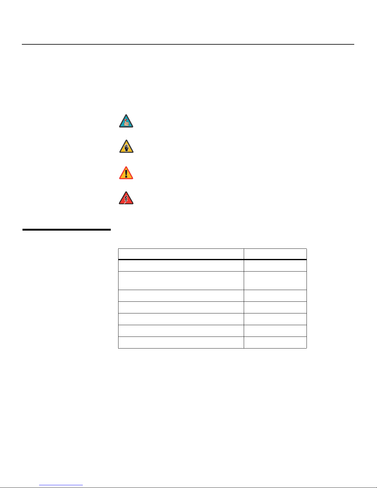
Note
Caution
WARNING
DANGER!
Graphic Conventions: These symbols appear in numerous places throughout the manual,
to emphasize points that you must keep in mind to avoid problems with your equipment or
injury:
TIPS highlight time-saving short cuts and helpful guidelines for using
certain features.
NOTES emphasize text with unusual importance or special significance.
They also provide supplemental information.
CAUTIONS alert users that a given action or omitted action can degrade
performance or cause a malfunction.
Y
WARNINGS appear when a given action or omitted action can result in
damage to the equipment, or possible non-fatal injury to the user.
DANGER appears when a given action can cause severe injury or death.
1.2
Using This Manual
Use the following table to locate the specific information you need in this manual.
IMINAR
Information about obtaining service iv
General information about the Vision Model
140/150 LightAmp™ Projector and VHD Controller
Installation instructions 17
First-time configuration instructions 39
L
PRE
Advanced configuration instructions 74
Troubleshooting tips 85
Product specifications 97
If you need... ... Turn to page:
3
2 Vision Model 140/150 Installation/Operation Manual

Introduction
Note
Vidikron’s Vision Model 140 and Model 150 bring our most advanced technology, 1080p
resolution and the world’s first THX
awesome fashion.
The Vision 140/150 uses a new, ingeniously engineered 3-chip DLP™ light engine, combined
with an advanced Xenon LightAmp™ lamp illumination system to bring astoundingly high
performance and ultra-high resolution to the very best home theaters on the planet.
The Vision 140 features a 1000W Xenon lamp, while the Vision 150 uses a 1.2-kW Xenon lamp
to produce our brightest 1080p pictures ever. Four, high-precision zoom lenses are available
with broad motorized horizontal and vertical lens shift capability. Vidikron engineers have
ensured that light is efficiently culminated through the implementation of our advanced V2™
technology and have also engineered ISF™ calibration standards into these projectors.
®
Certified home video products together in truly
Y
The Vision 140/150 is furnished with Vidikron’s newest, next-generation, all-digital VHD
Controller, featuring advanced Imagix™ processing, superb scaling, and the industry’s most
advanced aspect ratio control system.
For uncompromising widescreen reproduction of movies originally filmed in the “scope”
(2.35:1) format, the Vision 140/150 can be equipped with Vidikron’s patent-pending
CineWide™ technology, a combination of software, electronics and high-quality anamorphic
optics. CineWide maintains constant vertical height on the screen just as in a movie theater.
When a viewer transitions from 1.78:1 (16:9) program material to 2.35:1, the image simply
gets wider while full height is maintained. Also available with the Vision 140/150 is CineWide
with AutoScope™, an enhanced, remote-controlled motorized version of CineWide.
CineWide requires the use of a 2.35:1 or similar aspect ratio superwide format
screen.
IMINAR
L
1.3
Description, Features and
Benefits
Discrete IR and RS-232 control make custom installation seamless, while discrete source and
aspect ratio selection accommodate any automation control system.
PRE
Vision Model 140/150 Installation/Operation Manual 3

Introduction
➤
➤
Key Features and Benefits The Vision 140/150 offers these key features and benefits:
• Native Resolution: 1920 x 1080
• Three-chip Digital Light Processing (DLP) system
• Two HDMI Inputs (on VHD Controller) with High-bandwidth Digital Content Protection
(HDCP)
•HDTV Compatible
• Multiple lens options for stunning sharpness and throw distance flexibility
Parts List Your Vision 140/150 is shipped with the following items. If any items are missing or damaged,
please contact your Vidikron dealer or Vidikron Customer Service at (888) 4VIDIKRON.
• Vision Model 140/150 LightAmp™ Projector and VHD Controller
•Remote Control Unit and two (2), AAA-size batteries
• TheaterMaster Remote Control Unit and four (4), AAA-size batteries
• Two (2), 110-VAC power cords (Vision 140)
– OR –
One 110-VAC and one 220-VAC power cord (Vision 150)
• RJ-11 Telephone Cable, 50 feet (15.24 meters)
• Serial Port Adapter, RJ-11 Female to DB-9 Male
• Rack-mounting brackets and hardware for the VHD Controller
• Warranty information and registration card
• Vision Model 140/150 Installation/Operation Manual (this document)
IMINAR
Y
Optional Accessories:
• CineWide™ technology (fixed, secondary anamorphic lens)
• CineWide™ with AutoScope™ system (secondary anamorphic lens and motorized mount)
• Ceiling mount kit (part number 956-0096-00)
L
PRE
4 Vision Model 140/150 Installation/Operation Manual
2Controls and Functions
AC IN 220V 50HZ
1
9
3
5
11
8
10
4
6
2
7
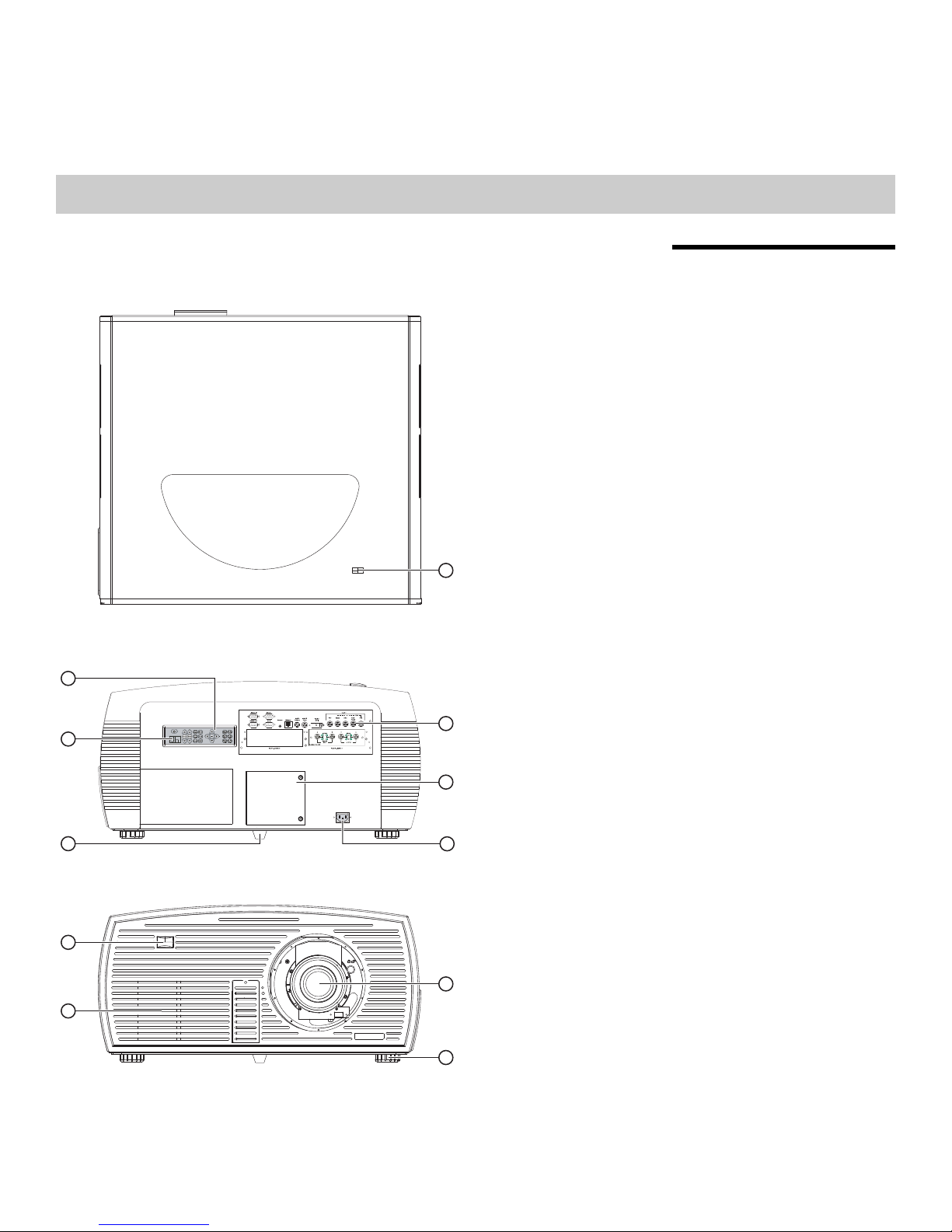
Figure 2-1 shows the key Vision 140/150 components.
L
2.1
Vision 140/150 at a Glance
Y
IMINAR
PRE
Figure 2-1. Vision 140/150 Top/Rear/Front View
Vision Model 140/150 Installation/Operation Manual 5

Controls and Functions
1. TOP IR SENSOR
2. BUILT-IN KEYPAD
The built-in keypad is located at the back of the projector, beside the input panel. Use it
similarly to the TheaterMaster Remote Control to perform service-related tasks on the
projector.
3. INPUT PANEL
Connect the VHD Controller outputs here.
4. LED STATUS DISPLAY
Indicates current operating status of the projector.
5. LAMP COVER
Remove this cover to access the lamp compartment.
6. REAR FOOT (Stationary)
7. POWER INPUT (200 to 240 VAC)
Connect the Vision 140/150 to power here. (The Vision 140 requires 100 to 240 VAC; the
Vision
150 requires 200 to 240 VAC.)
8. FRONT IR SENSOR
9. PROJECTION LENS
10. INTAKE VENT
Allows cool air to enter the projector, to help maintain proper operating temperature.
11. ADJUSTABLE FEET (2)
Located on the underside of the projector are two adjustable feet. Raise or lower these
feet when positioning the projector to ensure it is level on all sides so the displayed
image will appear rectangular without any keystone.
IMINAR
L
PRE
Y
6 Vision Model 140/150 Installation/Operation Manual

Controls and Functions
Figure 2-2 shows the Vision 140/150 rear input panel.
1 7 863 5 92 4
11 10
Figure 2-2. Vision 140/150 Input Panel
1. RS232 IN
Connect the RS-232 output from the VHD Controller here, using the provided
RJ11-to-DB9 adapter and communication cable.
2. RS232 OUT
Not used.
IMINAR
L
3. RS422
Not used.
4. GPIO
Not used.
5. REMOTE
Wired input from an external remote control or infrared receiver.
6. ETHERNET
Reserved for future use.
7. INPUT 3 (Video) / INPUT 4 (S-Video)
Not used. Connect all video sources to the VHD Controller.
8. INPUT 2 (DVI)
HDCP-compliant digital video input. Connect the HDMI output from the VHD Controller
to this input.
PRE
2.2
Vision 140/150 Input Panel
Y
9. INPUT 1 (RGBHV)
Not used. Connect all video sources to the VHD Controller.
10. INPUT 5 (Option 1)
Reserved for future use.
11. INPUT 6 (Option 2)
Reserved for future use.
Vision Model 140/150 Installation/Operation Manual 7
Controls and Functions
Note
2.3
Vision 140/150 Rear-Panel
Keypad
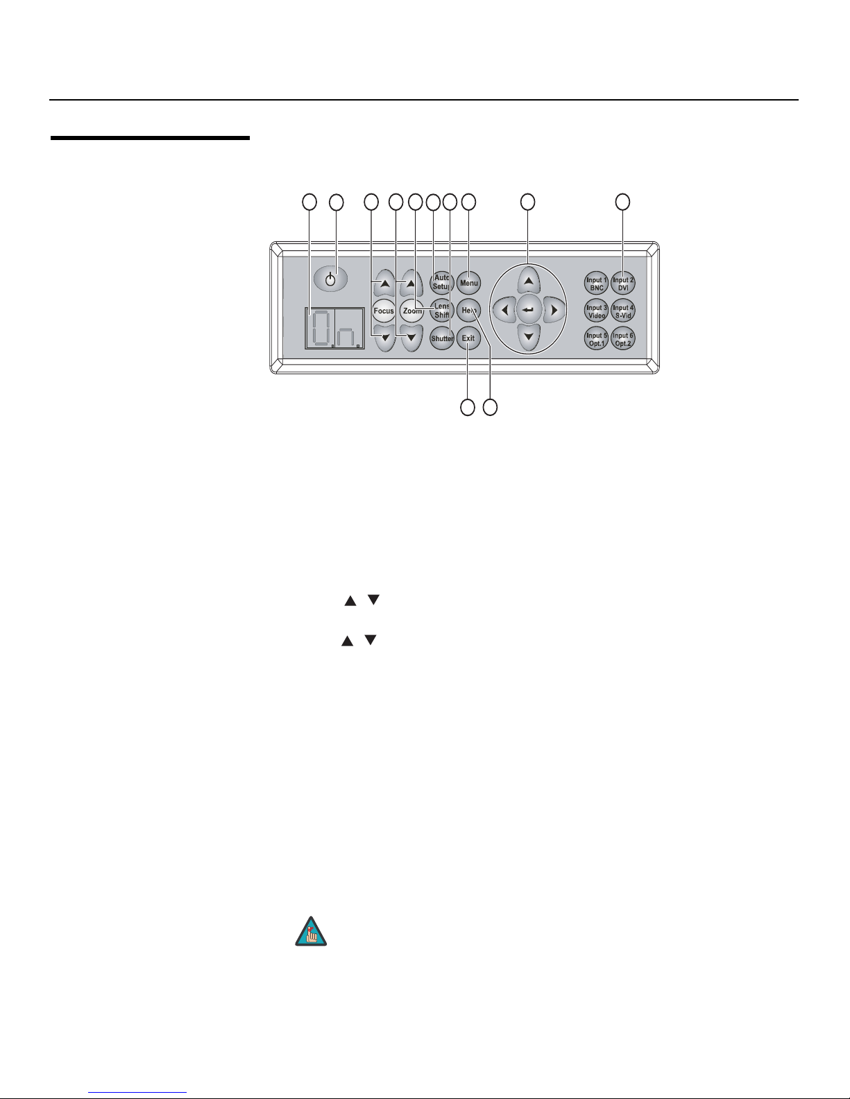
Figure 2-3 shows the Vision 140/150 rear-panel keypad.
1 3 4 7 8
2
5
6
9 10
Y
12
11
Figure 2-3. Vision 140/150 Rear-Panel Keypad
1. LED STATUS DISPLAY
The LED status window displays an active pattern of segments to indicate the projector
is changing its state from powered down to powered up. The message “On” appears in
the display when the projector has completed its initialization and is ready for use.
2. POWER BUTTON
Not used. Use the VHD Controller to turn the projector on or off.
3. FOCUS ( / )
Use these buttons to focus the projected image.
4. ZOOM ( / )
Use these buttons to increase or decrease the projected image size.
IMINAR
L
5. LENS SHIFT
PRE
Press this button to access the motorized lens shift controls.
6. AUTO SETUP
Press this button to initiate an automated process in which the projector optimizes
critical display parameters for the current source.
7. SHUTTER
Press and hold this button for two seconds to toggle the internal mechanical shutter
blade closed or open. A closed shutter blanks the display (turns it to black). Close the
shutter to mute all display while maintaining access to projector functions. Opening the
shutter restores the image.
8. MENU
Press this button to show or hide the projector menus.
The Vision 140/150 has its own internal menu system, separate from that
of the VHD Controller. However, it is intended for use by trained service
personnel only.
8 Vision Model 140/150 Installation/Operation Manual

9. Menu Navigation Buttons:
UP BUTTON ( )
Used to move the menu cursor up in the Vision 140/150 menu system.
LEFT BUTTON ( )
Used to move the menu cursor left in the Vision 140/150 menu system.
DOWN BUTTON ( )
Used to move the menu cursor down in the Vision 140/150 menu system.
RIGHT BUTTON ( )
Used to move the menu cursor right in the Vision 140/150 menu system.
ENTER BUTTON
When an item is highlighted on the On-Screen Display, the ENTER button selects the
item.
10. INPUT 2 (DVI)
Press this button to select projector Input 2 (HDMI output from the VHD Controller).
11. HELP
Press HELP to display on-screen help text. Press HELP again (or EXIT) to hide it.
12. EXIT
When in the menu structure, the EXIT button brings the menu back one page or cancels
the current function.
Controls and Functions
Y
IMINAR
L
PRE
Vision Model 140/150 Installation/Operation Manual 9
Controls and Functions
2.4
VHD Controller Front
Panel
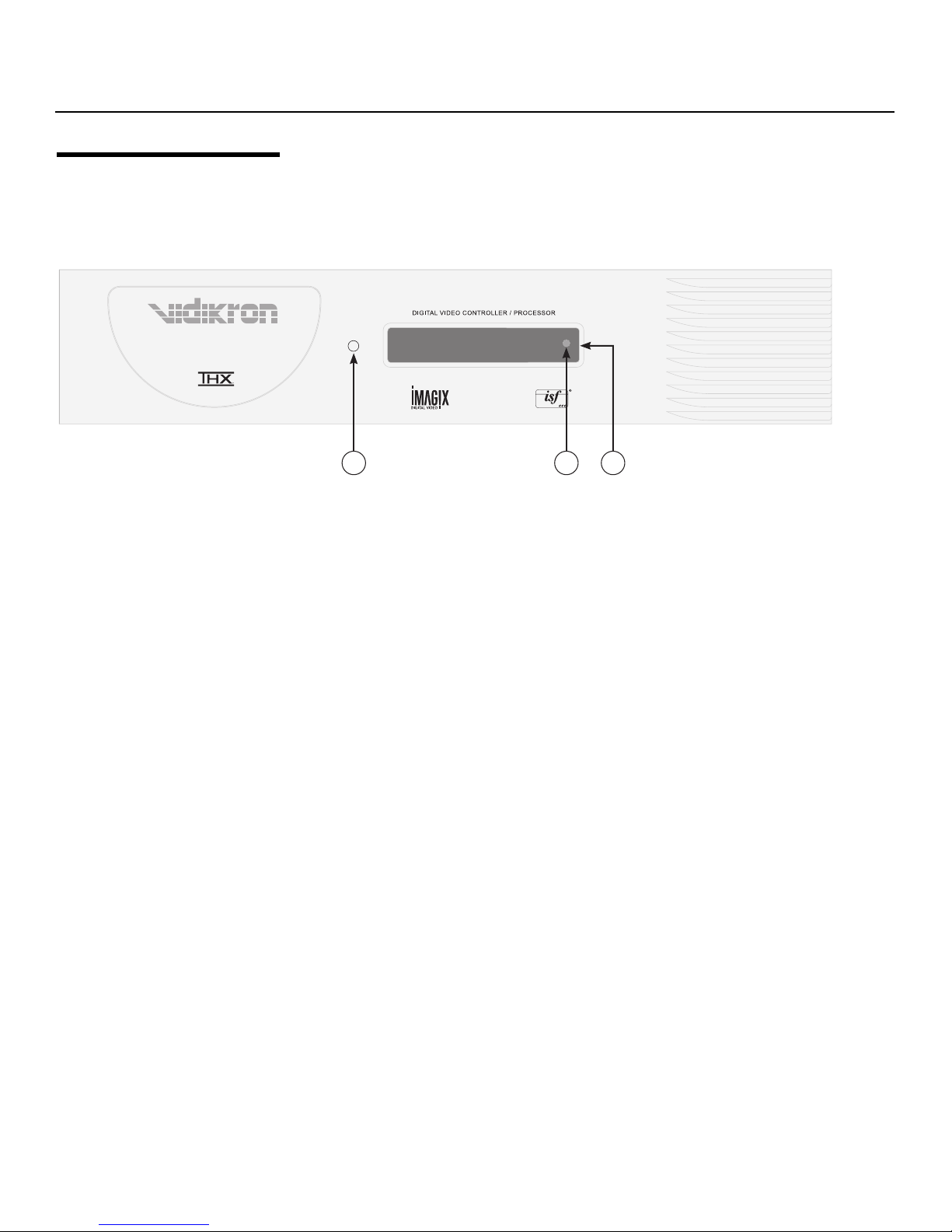
Figure 2-4. VHD Controller Front Panel
Figure 2-4 shows the controls and indicators on the VHD Controller front panel; the
paragraphs that follow describe them.
1. POWER BUTTON
2. IR SENSOR
3. VACUUM FLUORESCENT DISPLAY
Component SD NTSC 480i
16:9 V150
Y
1 2 3
Press once to toggle from standby mode to on mode. Press it again to return to standby
mode. For a discrete on or off command, you can use the direct access buttons on the
remote control.
IMINAR
Receives IR commands from the remote.
L
Can be used instead of the On-Screen Display (OSD). Displays currently-selected menu
or – if no menu is selected – the current source, signal format (NTSC or PAL), input
resolution and aspect ratio.
PRE
10 Vision Model 140/150 Installation/Operation Manual
Controls and Functions
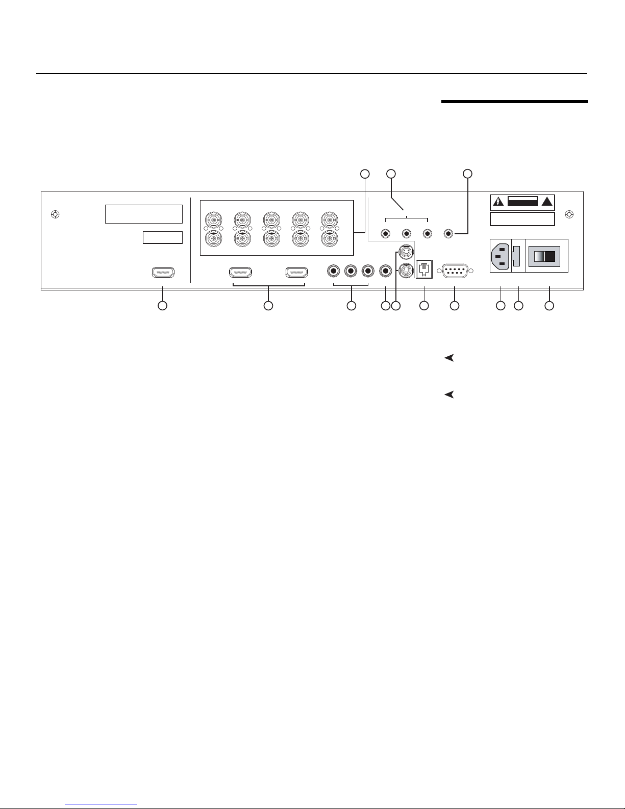
Figure 2-5 shows the rear connector panel on the VHD Controller.
3
Serial No
Model
Video Processor / Controller
1
R/Pr G/Y B/Pb
R/Pr G/Y B/Pb H V
INPUTS
HDMI 1 HDMI 2HDMI Out
2
HV
HD1
HD2
Pb Pr Y
Component Video
Video
4
Figure 2-5. VHD Controller Rear Panel
Connect this to Input 2 (DVI) on the Vision 140/150 (see Figure 2-2).
Two, HDCP-compliant digital video inputs for connecting a DVD player or HD tuner with
IMINAR
a DVI or HDMI output.
3. HD1 / HD2 (5 x Analog BNCs)
L
Two inputs (five BNCs per input) for connecting either RGB or component
high-definition television signals. The VHD Controller automatically detects the signal
format: RGB(HV) or YPrPb, 480p, 720p, 480i, 576i or 1080i.
4. COMPONENT VIDEO (RCA connectors)
Standard Definition (480i/576i) Component (YPrPb) input. This is the input for
component video from sources such as DVD players.
PRE
2.5
VHD Controller Rear Panel
79
SYSTEM CONTROL INTERFACE
TRIGGERS
2
1
S-Video 1
Y
S-Video 2
RS-232 Out
5
6
IR
3
WARNING:
TO REDUCE THE RISK OF FIRE
OR ELECTRIC SHOCK, DO NOT EXPOSE
THIS APPLIANCE TO RAIN OR MOISTURE.
RS-232 Control
10
8
Outputs1. HDMI OUT
Inputs2. HDMI 1 / HDMI 2 (Digital)
CAUTION
RISK OF ELECTRIC SHOCK
DO NOT OPEN
AVIS: RISQUE DE CHOC ELECTRIQUE-NE PAS OUVRIR
CAUTION:
TO REDUCE THE RISK OF ELECTRIC
SHOCK, DO NOT REMOVE COVER. NO USERSERVICEABLE PARTS INSIDE. REFER SERVICING
TO QUALIFIED SERVICE CENTER.
100-230VAC 50-60 Hz, 165 Watts Max
Made In USA
11
12 13
!
For best results, do not run your DVD player in progressive mode.
5. COMPOSITE VIDEO INPUT
Standard composite video input for connecting a VCR, laser disc player or other
composite video source.
6. S-VIDEO 1 / S-VIDEO 2
Two, standard S-Video inputs for connecting a DVD player, satellite receiver or Super
VHS (S-VHS) VCR.
7. 12-VOLT (750 mA) TRIGGER OUTPUTS
Connection for up to three (3), 12-volt trigger-controlled devices such as retractable
screens or screen masks.
8. RS-232 OUTPUT
Connect this to the RS232 IN input on the projector, using the provided communication
cable.
Vision Model 140/150 Installation/Operation Manual 11

Controls and Functions
Note
9. IR
Wired input from a wired remote control or infrared receiver. It is a 3.5-mm, mini phono
jack, wired as follows:
Ring = +5V
Tip = IR Input
Sleeve = Ground
10. RS-232 CONTROL PORT
A female, 9-pin D-sub connector for interfacing with a PC or home theater
automation/control system.
11. POWER INPUT (100 to 240 VAC)
Connect the VHD Controller to power here.
12. MAIN AC FUSE
This is the main AC input fuse (5mm x 20mm, 500 mA, 250V slow-blow).
13. MAIN POWER SWITCH
Disconnects or applies power to the VHD Controller.
When an external remote control or infrared receiver is connected to the
wired IR input, the IR sensor on the front of the VHD is disabled.
Y
IMINAR
L
PRE
12 Vision Model 140/150 Installation/Operation Manual
Controls and Functions
1
2
7
10
14
19
22
16
11
4
3
5
6
8
12
17
18
20
21
13
9
15
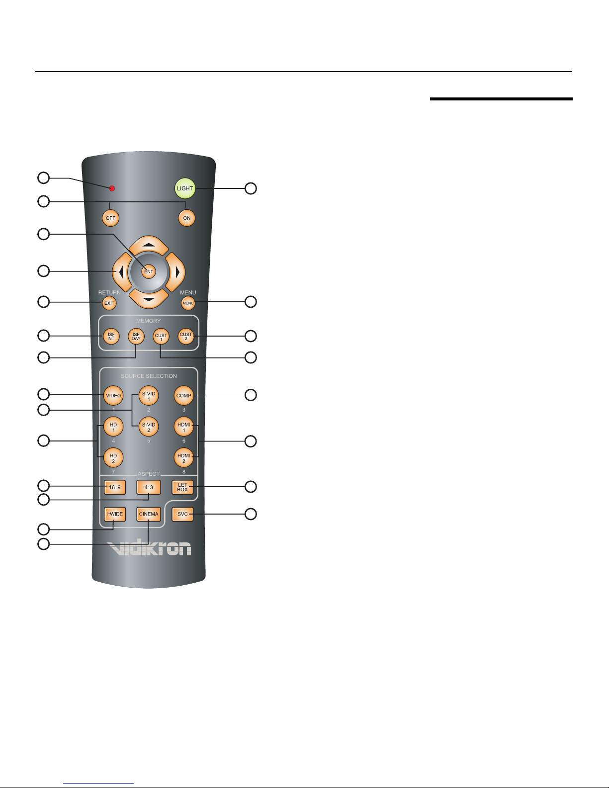
Figure 2-6 shows the Vision 140/150 remote control, and the paragraphs that follow describe
its functionality.
2.6
Vision 140/150 Remote
Control Unit
Y
IMINAR
L
Figure 2-6. VHD Controller/Vision 140/150 Remote Control
Vision Model 140/150 Installation/Operation Manual 13
PRE

Controls and Functions
Note
Note
Note
Note
1. IR OUTPUT INDICATOR
Lights when a button is pressed to indicate that an IR signal is being transmitted.
2. LIGHT
Press to illuminate the buttons.
3. ON / OFF
Press to turn the projector on or off.
4. ENT (Enter)
Press to select a highlighted menu item or confirm a changed setting.
On some remote control units, this button is where the RETURN/EXIT
button (item #6) appears here.
Y
5. Cursor Buttons ( , , , )
Use these buttons to select items or settings, adjust settings or switch display patterns.
When no menu is present on-screen, the UP and DOWN buttons toggle through the
available aspect ratios, in this order:
UP Button = 16:9 - Standard (4:3) - Letterbox - IntelliWide - Cinema - IntelliWide 2.35
DOWN Button = IntelliWide 2.35 - Cinema - IntelliWide - Letterbox - Standard (4:3) - 16:9
Intelliwide 2.35 is available only on the Vision 140/150/CineWide. For
more information about aspect ratios, refer to
Table 4-1.
Likewise, the LEFT and RIGHT buttons toggle through the different source inputs, in this
order:
LEFT Button = HDMI 2 - HDMI 1 - HD/RGB2 - HD/RGB 1 - Component SD - S-Video 2 S-Video 1 - Composite
RIGHT Button = Composite - S-Video 1 - S-Video 2 - Component SD - HD/RGB 1 HD/RGB
IMINAR
L
2 - HDMI 1 - HDMI 2
PRE
6. RETURN/EXIT
Press this button to exit the current menu and return to the previous one, or to cancel an
operation.
7. MENU
Press this button to access the OSD controls.
The “direct select” function of the UP, DOWN, LEFT and RIGHT buttons is
available only on the analog inputs (HD/RGB, SD Component, Composite
and S-Video).
On some remote control units, the ENT (Enter) button (item #4) is in this
location.
14 Vision Model 140/150 Installation/Operation Manual

Memory Preset Buttons:
8. ISF NT (Night)
Press to recall settings for the current input from the “ISF Night” memory preset.
9. ISF DAY
Press to recall settings for the current input from the “ISF Day” memory preset.
10. CUST 2
Press to recall settings for the current input from the “Custom 2” memory preset.
11. CUST 1
Press to recall settings for the current input from the “Custom 1” memory preset.
12. VIDEO (1)
Press to select Composite video input as the source or to enter the numeric character “1.”
13. S-VID 1 (2) / S-VID 2 (5) (S-Video)
Press to select an S-Video input or to enter the numeric character “2” or “5.”
14. COMP (Component) (3)
Press to select Component SD (480i/576i) video input as the source or to enter the
numeric character “3.”
15. HD 1 (4) / HD 2 (7)
Press to select a HD (RGBHV or YPbPr component) input or to enter the numeric
character “4” or “7.”
16. HDMI 1 (6) / HDMI 2 (8)
Press to select a Digital Video input or to enter the numeric character “6” or “8.”
Controls and Functions
Y
Aspect Ratio Selection Buttons:
Use these buttons to select an aspect ratio directly or to enter numeric characters, as follows:
17. 16:9 (9)
For viewing 16:9 DVDs or HDTV programs in their native aspect ratio.
18. 4:3 (0)
Scales the input signal to fit 4:3 display mode in the center of the screen.
19. LETBOX (Letterbox)
For viewing LaserDisc movies or non-anamorphic DVDs on a 16:9 screen.
20. I-WIDE (IntelliWide)
Enlarges a 4:3 image horizontally in a NON-linear fashion to fit 16:9 full screen display.
21. CINEMA
For viewing 2.35:1 source material.
22. SVC (CineWide-equipped projectors only)
Selects the IntelliWide 2.35 aspect ratio, used for viewing 16:9 source material on a 2.35:1
screen.
PRE
IMINAR
L
Vision Model 140/150 Installation/Operation Manual 15

Controls and Functions
Notes:
Y
IMINAR
L
PRE
16 Vision Model 140/150 Installation/Operation Manual
 Loading...