

Vidikron VDP-720, VDP-80-720 Owner's Operating Manual

OWNER’S OPERATING MANUAL
VDP-80-720
DIGITAL VIDEO PROCESSOR
(optimized for 720p Vidikron high-definition display devices)
VERSION 1.0


TWO YEAR LIMITED WARRANTY
For Projectors, Video Processors and Controllers
Congratulations on your purchase of a Vidikron video product and welcome to the Vidikron family! With proper installation, setup
and care, you should enjoy many years of unparalleled video performance.
This is a LIMITED WARRANTY as defined in the Magnuson-Moss Warranty Act. Please read it carefully and retain it with your other
important documents.
WHAT IS COVERED UNDER THE TERMS OF THIS LIMITED WARRANTY:
SERVICE LABOR: Vidikron will pay for service labor by Vidikron Authorized Service Center when needed as a result of manufacturing
defect for a period of two (2) years from the effective date of delivery to the end user (excluding the lamp).
Y
PARTS: (Not including the lamp) Vidikron will provide new or rebuilt replacement parts for the parts that fail due to defects in
materials or workmanship for a period of two (2) years from the effective date of delivery to the end user. Such replacement parts
are then subsequently warranted for the remaining portion (if any) of the original warranty period.
WHAT IS NOT COVERED UNDER THE TERMS OF THIS LIMITED WARRANTY:
This Limited Warranty only covers failure due to defects in materials and workmanship that occur during normal use and does not
cover normal maintenance. This Limited Warranty does not cover cabinets or any appearance items; failure resulting from
accident, misuse, abuse, neglect, mishandling, misapplication, faulty or improper installation or setup adjustments; improper
maintenance, alteration, improper use of any input signal; damage due to lightning or power line surges, spikes and brownouts;
damage that occurs during shipping or transit; or damage that is attributed to acts of God. In the case of remote control units,
damage resulting from leaking, old, damaged or improper batteries is also excluded from coverage under this Limited Warranty.
IMINAR
CAUTION: THIS LIMITED WARRANTY ONLY COVERS VIDIKRON PRODUCTS PURCHASED FROM VIDIKRON AUTHORIZED DEALERS.
ALL OTHER PRODUCTS ARE SPECIFICALLY EXCLUDED FROM COVERAGE UNDER THIS LIMITED WARRANTY. MOREOVER, DAMAGE
RESULTING DIRECTLY OR INDIRECTLY FROM IMPROPER INSTALLATION OR SETUP IS SPECIFICALLY EXCLUDED FROM COVERAGE
UNDER THIS LIMITED WARRANTY.
RIGHTS, LIMITS AND EXCLUSIONS:
L
PRE
Vidikron limits its obligations under any implied warranties under state laws to a period not to exceed the warranty period. There
are no express warranties. Vidikron also excludes any obligation on its part for incidental or consequential damages related to the
failure of this product to function properly. Some states do not allow limitations on how long an implied warranty lasts, and some
states do not allow the exclusion or limitation of incidental or consequential damages. So the above limitations or exclusions may
not apply to you. This warranty gives you specific legal rights, and you may also have other rights that vary from state to state.
EFFECTIVE WARRANTY DATE:
This warranty begins on the effective date of delivery to the end user. For your convenience, keep the original bill of sale as
evidence of the purchase date.
IMPORTANT -- WARRANTY REGISTRATION:
Please fill out and mail your warranty registration card. It is imperative that Vidikron knows how to reach you promptly if we should
discover a safety problem or product update for which you must be notified.
Vidikron VDP-80-720 Owner’s Operating Manual iii

CONTACT A VIDIKRON AUTHORIZED SERVICE CENTER TO OBTAIN SERVICE:
Repairs made under the terms of this Limited Warranty covering your Vidikron video product will be performed at the location of
the product, during usual working hours, providing location of product is within normal operating distance from a Vidikron
Authorized Service Center. In some instances it may be necessary for the product to be returned to the Vidikron factory for repairs.
If, solely in Vidikron’s judgment, location of product to be repaired is beyond normal operating distance of the closest Vidikron
Authorized Service Center, or the repair requires the unit be returned to the Vidikron factory, it is the owner’s responsibility to
arrange for shipment of the product for repair. These arrangements must be made through the selling Vidikron Dealer. If this is not
possible, contact Vidikron directly for a Return Authorization number and shipping instructions. Vidikron will return product
transportation prepaid in the United States, unless no product defect is discovered. In that instance, shipping costs will be the
responsibility of the owner.
COPYRIGHT AND TRADEMARKS:
© Copyright 2006 Vidikron. This document contains proprietary information protected by copyright. All rights are reserved. No part
of this manual may be reproduced by any mechanical, electronic or other means, in any form, without prior written permission of
the manufacturer.
All trademarks and registered trademarks are the property of their respective owners.
Y
IMINAR
L
PRE
iv Vidikron VDP-80-720 Owner’s Operating Manual

ADDITIONAL INFORMATION:
To locate the name and address of the nearest Vidikron Authorized Service Center, or for additional information about this Limited
Warranty, please call or write:
VIDIKRON
Attn: Customer Service Department
2900 Faber Street
Union City, CA 94587
Ph: (510) 324-5900
Fax: (510) 324-5905
Toll Free: (888) 4VIDIKRON
VIDIKRON PRODUCT INFORMATION
RETAIN THIS INFORMATION FOR YOUR RECORDS
Y
IMINAR
_________________________________________________________ ________________________________________
L
Model Purchased Date
____________________________________________________________________________________________________________
Serial Number
____________________________________________________________________________________________________________
Vidikron Authorized Dealer Name
____________________________________________________________________________________________________________
PRE
Address
____________________________________________ __________________ ________________________
City State/Province Postal Code
____________________________________________ _______________________________________________________
Phone Fax
Vidikron VDP-80-720 Owner’s Operating Manual v
Safety Precautions
Thank you for your purchase of this quality Vidikron product! It has been designed to provide you with the quality of video that is
expected in a home theater. For the best performance, please read this manual carefully as it is your guide through the menus and
operation.
WAR NING
CAUTION
RISK OFELECTRIC SHOCK
DO NOTOPEN
TO REDUCE THE RISK OF ELECTRIC SHOCK
DO NOT REMOVE COVER (OR BACK)
NO USER SERVICEABLE PARTS INSIDE.
REFER SERVICING TO QUALIFIED
This equipment has been tested and found to comply with the limits for a Class B digital device, pursuant to Part 15 of the FCC
Rules. These limits are designed to provide reasonable protection against harmful interference in a residential installation.
1. Read these instructions.
2. Keep these instructions.
3. Heed all warnings.
4. Do not use this equipment near water, outdoors or otherwise exposed to the elements.
5. Clean only with a dry cloth.
6. Do not block any ventilation openings.
CAUTION:
SERVICE PERSONNEL.
This symbol is intended to alert the user to the presence of
uninsulated “dangerous voltage” within the product’s enclosure that
may be of sufficient magnitude to constitute a risk of electric shock.
This symbol is intended to alert the user to the presence of important
operating and maintenance (servicing) instructions in the literature
accompanying the appliance.
Y
IMINAR
L
7. Do not install near any heat sources such as radiators, heat registers, stoves, or other apparatus (including amplifiers) that
produce heat.
8. Do not defeat the safety feature of the polarized or grounding type plug. A polarized type plug has two blades with one wider
than the other. A grounding type plug has two blades and a third grounding prong. The third prong is provided for your safety.
If the provided plug does not fit into your outlet, consult an electrician for the replacement of the obsolete outlet.
9. The 12V trigger only outputs DC 12V signal for triggering. Do not connect to any other power input or output. This could cause
damage to this unit.
10. Only use accessories specified by Vidikron.
11. Keep the packing material in case the equipment should ever need to be shipped.
12. Unplug this processor during lightning storms or when it will not be used for an extended period of time.
13. Refer all servicing to qualified service personnel. Servicing is required when the processor has been damaged in any way,
objects have fallen or spilled into the processor, the processor has been exposed to rain or moisture, does not operate
normally, or has been dropped.
PRE
vi Vidikron VDP-80-720 Owner’s Operating Manual

1Table of Contents
TWO YEAR LIMITED WARRANTY ............................................................................................. iii
Safety Precautions ................................................................................................................... vi
1. Introduction ........................................................................................................................ 1
About This Manual ............................................................................................................................................ 1
Target Audience......................................................................................................................................... 1
If You Have Comments About This Manual... .................................................................................. 1
Textual and Graphic Conventions ....................................................................................................... 1
Using This Manual ............................................................................................................................................. 2
Description, Features and Benefits ............................................................................................................. 3
Product Overview ...................................................................................................................................... 3
Key Features and Benefits....................................................................................................................... 5
Parts List ........................................................................................................................................................ 6
2. Controls and Functions ...................................................................................................... 7
VDP-80-720 at a Glance ................................................................................................................................... 7
Controls, Indicators and Connectors .................................................................................................. 7
VDP-80-720 Remote Control ......................................................................................................................... 9
3. Installation ........................................................................................................................ 13
Remote Control ................................................................................................................................................ 13
Notes on Batteries ...................................................................................................................................13
PRE
Notes on Remote Control Operation................................................................................................13
Quick Setup .......................................................................................................................................................14
Installation Considerations ..........................................................................................................................15
Shelf Installation or Rack Mounting .................................................................................................. 16
IMINAR
L
Y
Connections to the VDP-80-720 ................................................................................................................. 17
Vidikron VDP-80-720 Owner’s Operating Manual vii
Connecting Display Devices to the VDP-80-720 .......................................................................... 17
Connecting the VDP-80-720 to Source Components................................................................. 18
RS-232 Controller Connection ............................................................................................................ 22

Table of Contents
4. Operation .......................................................................................................................... 23
Turning on the Power ....................................................................................................................................23
Changing the Aspect Ratio ..........................................................................................................................23
Using the On-Screen Menus ........................................................................................................................25
Main Menu ................................................................................................................................................27
Source Type ...............................................................................................................................................27
Picture Adjust ............................................................................................................................................27
Input Adjust ...............................................................................................................................................32
Input Name ................................................................................................................................................33
DVI Setup ....................................................................................................................................................33
Copy Settings ............................................................................................................................................34
Side Gray-Bar Level .................................................................................................................................34
Vertical Rate ...............................................................................................................................................34
LCD Setup ...................................................................................................................................................34
Input Display .............................................................................................................................................34
Lock............................................................................................................................................................... 34
Power Management ...............................................................................................................................34
Save Settings ............................................................................................................................................. 35
Defaults .......................................................................................................................................................35
Using the Remote Numeric Commands ................................................................................................. 35
5. Maintenance and Troubleshooting ................................................................................ 39
Troubleshooting Tips .....................................................................................................................................39
6. Serial Communications ....................................................................................................41
RS-232 Connection and Port Configuration ..........................................................................................41
PRE
Serial Command Syntax ................................................................................................................................41
7. Specifications .................................................................................................................... 43
IMINAR
L
Y
VDP-80-720 Specifications ........................................................................................................................... 43
viii Vidikron VDP-80-720 Owner’s Operating Manual

1List of Figures
1-1. VDP-80-720 Functional Block Diagram. . . . . . . . . . . . . . . . . . . . . . . . . . . . . . . . . . . . . . . . . . . . . . . . . . . 3
2-1. VDP-80-720 Controls, Indicators and Connectors. . . . . . . . . . . . . . . . . . . . . . . . . . . . . . . . . . . . . . . . . 7
2-2. VDP-80-720 Remote Control . . . . . . . . . . . . . . . . . . . . . . . . . . . . . . . . . . . . . . . . . . . . . . . . . . . . . . . . . . . . 9
2-3. VDP-80-720 Remote Control Menu Structure . . . . . . . . . . . . . . . . . . . . . . . . . . . . . . . . . . . . . . . . . . . 10
3-1. Display Device Connections . . . . . . . . . . . . . . . . . . . . . . . . . . . . . . . . . . . . . . . . . . . . . . . . . . . . . . . . . . . . 17
3-2. DVI or HDMI Source Connections. . . . . . . . . . . . . . . . . . . . . . . . . . . . . . . . . . . . . . . . . . . . . . . . . . . . . . . 18
3-3. RGB Source Connections . . . . . . . . . . . . . . . . . . . . . . . . . . . . . . . . . . . . . . . . . . . . . . . . . . . . . . . . . . . . . . . 19
3-4. SD/HD Component Video Source Connections . . . . . . . . . . . . . . . . . . . . . . . . . . . . . . . . . . . . . . . . . 20
3-5. Composite and S-Video Source Connections. . . . . . . . . . . . . . . . . . . . . . . . . . . . . . . . . . . . . . . . . . . . 21
3-6. SDI Source Connections. . . . . . . . . . . . . . . . . . . . . . . . . . . . . . . . . . . . . . . . . . . . . . . . . . . . . . . . . . . . . . . . 22
3-7. RS-232 Control System Connection. . . . . . . . . . . . . . . . . . . . . . . . . . . . . . . . . . . . . . . . . . . . . . . . . . . . . 22
4-1. VDP-80-720 OSD Menu Structure. . . . . . . . . . . . . . . . . . . . . . . . . . . . . . . . . . . . . . . . . . . . . . . . . . . . . . . 26
4-2. Typical PLUGE Pattern for Adjusting Brightness . . . . . . . . . . . . . . . . . . . . . . . . . . . . . . . . . . . . . . . . . 28
4-3. Typical Gray Bar Pattern for Adjusting Contrast . . . . . . . . . . . . . . . . . . . . . . . . . . . . . . . . . . . . . . . . . 29
4-4. Typical Color Bar Pattern for Adjusting Color Saturation and Tint . . . . . . . . . . . . . . . . . . . . . . . . 29
4-5. Typical Test Pattern for Adjusting Sharpness . . . . . . . . . . . . . . . . . . . . . . . . . . . . . . . . . . . . . . . . . . . . 32
IMINAR
L
Y
PRE
Vidikron VDP-80-720 Owner’s Operating Manual ix

List of Figures
Y
IMINAR
L
PRE
x Vidikron VDP-80-720 Owner’s Operating Manual

1Introduction
This Owner’s Manual describes how to install, set up and operate your Vidikron VDP-80
Digital Video Processor, optimized for use with Vidikron's 720p (progressive) high-definition
displays. Throughout this manual, the Vidikron VDP-80 Digital Video Processor is referred to
simply as the “VDP-80-720.”
most out of the VDP-80-720.
Vidikron has made every effort to ensure that this manual is accurate as of the date it was
printed. However, because of ongoing product improvements and customer feedback, it
may require updating from time to time. You can always find the latest version of this and
other Vidikron product manuals on-line, at www.vidikron.com.
Vidikron welcomes your comments about this manual. Send them to info@vidikron.com.
Text Conventions: The following conventions are used in this manual, in order to clarify the
information and instructions provided:
• Remote control button identifiers are set in upper-case bold type; for example, “Press EXIT
to return to the previous menu.”
• All keys with functional names are initial-capped, set in bold type and enclosed in angle
brackets. These keys are the following: <Enter>, <Spacebar>, <Control>, <Esc> and
<Tab>.
• <Enter> indicates that you may press either the RETURN or ENTER key on your computer
keyboard if it has both keys.
• Computer input (commands you type) and output (responses that appear on-screen) is
shown in monospace (fixed-width) type; for example: “To change the aspect ratio to
Anamorphic, type w.”
PRE
IMINAR
L
Y
1.1
About This Manual
Target AudienceVidikron has prepared this manual to help home theater installers and end users get the
If You Have Comments About
This Manual...
Textual and Graphic
Conventions
In addition to these conventions, underlining, boldface and/or italics are occasionally used to
highlight important information, as in this example:
Note
Vidikron VDP-80-720 Owner’s Operating Manual 1
Properly calibrate your display device input(s) BEFORE performing
any adjustments on the VDP-80-720. Consult the documentation for
your display device for detailed instructions.
Introduction
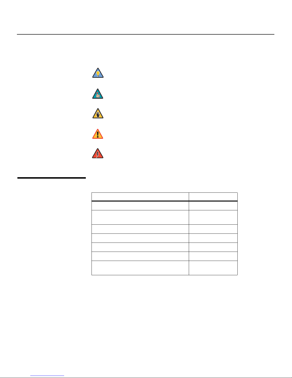
Graphic Conventions: These symbols appear in numerous places throughout the manual,
to emphasize points that you must keep in mind to avoid problems with your equipment or
injury:
1.2
Using This Manual
Tip
Note
Caution
TIPS highlight time-saving short cuts and helpful guidelines for using
certain features.
NOTES emphasize text with unusual importance or special significance.
They also provide supplemental information.
CAUTIONS alert users that a given action or omitted action can degrade
performance or cause a malfunction.
Y
WARNING
DANGER!
Use the following table to locate the specific information you need in this manual.
WARNINGS appear when a given action or omitted action can result in
damage to the equipment, or possible non-fatal injury to the user.
DANGER appears when a given action can cause severe injury or death.
IMINAR
If you need... ... Turn to page:
Information about obtaining service iv
L
General information about the VDP-80 Digital
Video Processor
Installation instructions 13
First-time configuration instructions 25
PRE
Advanced configuration instructions 35
Troubleshooting tips 39
Specifications for the VDP-80 Digital Video
Processor
3
43
2 Vidikron VDP-80-720 Owner’s Operating Manual
Introduction
Thank you for purchasing the Vidikron VDP-80 Digital Video Processor. The Vidikron VDP-80
Digital Video Processor provides a cornerstone for the ultimate home theater experience. It
has been designed to offer superior video processing quality, while providing for multiple
component integration with your high definition Vidikron home theater display. We hope
you find that the VDP-80-720 exceeds your expectations.
input, and output in the appropriate format and resolution. Standard definition (SD),
enhanced-definition (ED) and high-definition (HD) video inputs are all supported in addition
to a number of PC formats. Video inputs are converted to progressive video (as required) and
are scaled to the appropriate HD video output resolution.
Interlaced video has been in use for more than 50 years and is still the most common video
format. It displays half of the lines of picture information each sixtieth (or fiftieth) of a second.
Each half of the image is called a field and displays either all the even lines or all the odd lines.
So, an entire image, called a frame, takes a thirtieth (or twenty-fifth) of a second to display on
the screen. An “i” suffix on the resolution specification indicates an interlaced format.
In contrast, progressive video presents each frame as a whole. A “p” suffix on the resolution
specification indicates a progressive format. Converting interlaced video to progressive
video is referred to as “deinterlacing.”
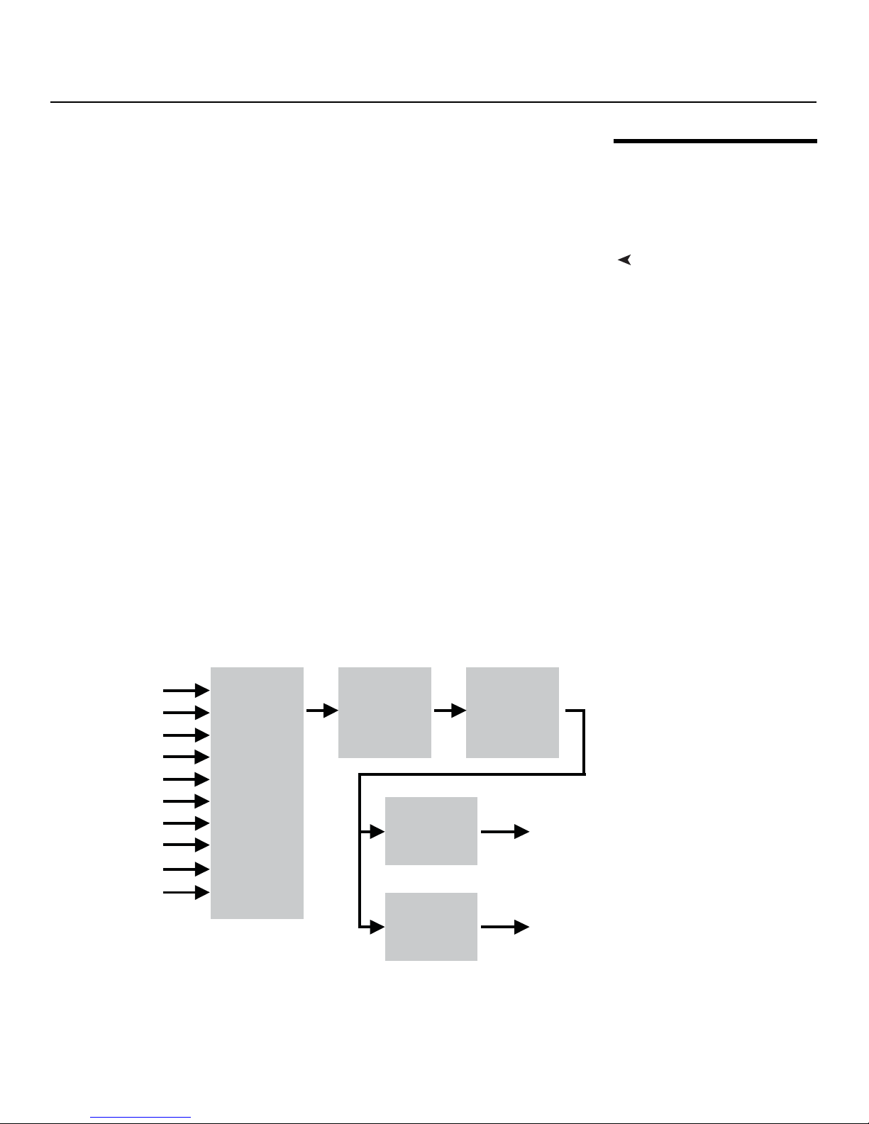
The VDP-80-720 is comprised of four major functional sections:
• Input selection, conversion to digital (if needed), and video decoding
• Deinterlacing
• Filtering and scaling
• Conversion to analog video, or output as digital DVI-D video
IMINAR
L
Y
1.3
Description, Features and
Benefits
Product OverviewThe primary functions of the VDP-80-720 are to act as a video switcher, process the selected
These functional blocks are shown in Figure 1-1.
DVI-D1
DVI-D2
YPbPr/RGB3
YPbPr/RGB4
S-Video/Vid5
S-Video/Vid6
YPbPr/S-Vid/Vid7
YPbPr/S-Vid/Vid8
SDI 9
SDI 0
Figure 1-1. VDP-80-720 Functional Block Diagram
PRE
Input
Select,
A-to-D
and TV
Decoder
De-Interlacer
DVI-D
with
HDCP
Digital-to-
Analog
Conversion
Filtering
and Scaling
DVI-D
RGBHV
Vidikron VDP-80-720 Owner’s Operating Manual 3

Introduction
Composite and S-Video inputs automatically select between NTSC, PAL and SECAM formats.
Component/RGB and DVI-D inputs accept SD, ED and/or HD video at either 50 or 59.94 Hertz.
HDCP encryption is supported for DVI-D inputs. If encrypted, DVI-D inputs are decrypted,
processed, scaled and then re-encrypted for output as DVI-D (as opposed to being simply
“passed through”). The digitized data is then decoded into a digital video format for further
processing. For analog outputs, video is over-sampled to provide the best possible image
quality.
HDCP encrypted DVI-D sources must be re-encrypted for output. As a
Note
result, the analog RGB output is disabled when a DVI input is selected.
Also, the display must support HDCP to show these encrypted sources. If
the video input is interlaced, it is first deinterlaced into a progressive
format.
Y
As part of the scaling process, digital filtering is used to enhance the image detail. This
enhancement allows standard definition inputs, such as DVDs, to appear to be much higher
resolution, even when viewed on the large screen sizes common in home theaters.
When the digital processing is completed, video is converted to analog using
digital-to-analog converters (DACs), or is output as DVI-D (digital) video. DVI-D video can use
either the “PC” range (full range black to white), or “video range” (reduced range for black to
white to allow for blacker-than-black and whiter-than-white levels).
An infrared (IR) remote control, or the serial RS232 port, is used for control and software
update. Critical display setup parameters have direct commands. Other functions use an
on-screen menu.
To allow options such as ISF day/night specific modes, the DVI-D and analog HD inputs
(Inputs 1 through 4) have four independent configuration memories. The other inputs have
two independent configuration memories.
IMINAR
L
PRE
4 Vidikron VDP-80-720 Owner’s Operating Manual

• Ten inputs (2 Composite/SVideo, 2 Composite/SVideo/SD-Component, 2 SD/HD
Component/RGB, 2 DVI-D and 2 SDI)
• Video processing/deinterlacing is supported for HDCP encrypted DVI-D inputs
• Component/RGB analog and DVI-D input accept 720p and 1080i sources
• Transcoding (for example, component to RGB) for digital and analog inputs
• 3:2, 3:3 and 2:2 film pull-down frame-reconstruction for SD sources
• Per-pixel motion-adaptive video deinterlacing for SD sources
• Multiple, independent configuration memories for each input
• Black-level and contrast calibration per memory
• Color, red-color-offset, green-color-offset calibration per memory
• Hue, red-hue-offset, green-hue-offset calibration per memory
• Y/C delay calibration with independent CB and CR delay
• Detail enhancing scaler
• Programmable vertical refresh rate
• Programmable screen aspect ratio
• DVI-D output with HDCP encryption support
• BNC analog output
• Backlit infrared remote control with on-screen menu system
• RS232 serial interface for control and software updates
• Silent operation (no fan)
IMINAR
Introduction
Key Features and BenefitsThe VDP-80-720 offers these key features and benefits:
Y
L
PRE
Vidikron VDP-80-720 Owner’s Operating Manual 5

Introduction
Parts List Your VDP-80-720 is shipped with the following items. If any items are missing or damaged,
➤
please contact your Vidikron dealer or Vidikron Customer Service at (888) 4VIDIKRON.
• VDP-80 Digital Video Processor
• External Power Supply
• Remote Control Unit and three (3), AA-size batteries
• Warranty information and registration card
• Vidikron VDP-80-720 Owner’s Operating Manual (this document)
•Rack-mount ears
Y
IMINAR
L
PRE
6 Vidikron VDP-80-720 Owner’s Operating Manual
2Controls and Functions
2.1
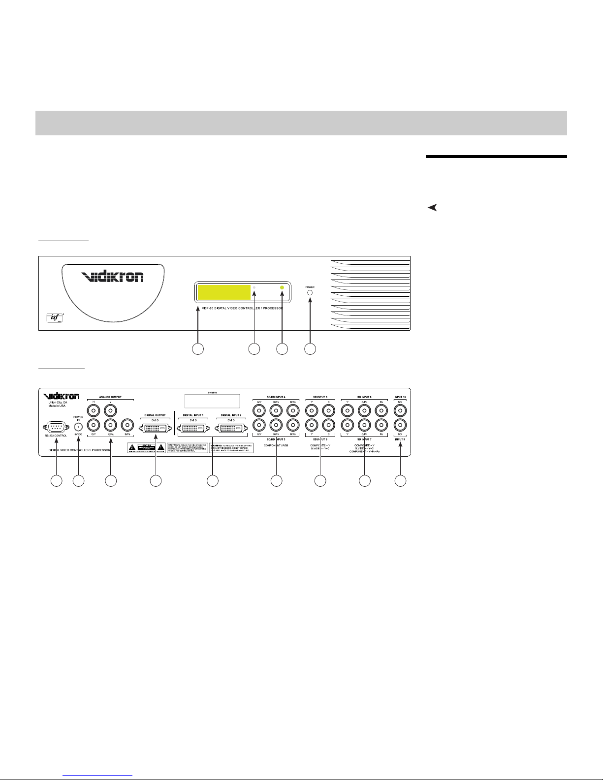
VDP-80-720 at a Glance
Figure 2-1 shows the locations of the VDP-80-720 controls, indicators and connectors.
Front Panel
IN8 ISF NGHT
1 42 3
Rear Panel
IMINAR
L
VDP-80-720
5 8 9 10 11 127 136
Controls, Indicators and
Connectors
Y
Figure 2-1. VDP-80-720 Controls, Indicators and Connectors
PRE
1. LIQUID CRYSTAL DISPLAY (LCD)
A 16-character, back-lit display that shows the currently-selected menu item. The LCD
can either show command activity or be used as a “power-on” indicator. This behavior is
user-selectable.
When the LCD is set to “activity” it illuminates for a short time after commands are
received. When the LCD is set to “power” it stays illuminated as long as the VDP-80-720 is
on, turning off briefly when a command is received.
2. INFRARED SENSOR
Receives the signals from the remote control.
3. POWER/STANDBY INDICATOR
Lights red to indicate that the VDP-80-720 is in standby mode; lights green to indicate
normal operation.
Vidikron VDP-80-720 Owner’s Operating Manual 7
 Loading...