

Vidikron SERIES 1080p User Manual

OWNER’S OPERATING MANUAL
70
SERIES 1080p DLP™ PROJECTORS
Vision 70
Vision 70/CineWide™
Vision 70/CineWide with AutoScope™
VERSION 1.0


TWO YEAR LIMITED WARRANTY
For Projectors, Video Processors and Controllers
Congratulations on your purchase of a Vidikron video product and welcome to the Vidikron family! With proper installation, setup
and care, you should enjoy many years of unparalleled video performance.
This is a LIMITED WARRANTY as defined in the Magnuson-Moss Warranty Act.
important documents.
WHAT IS COVERED UNDER THE TERMS OF THIS LIMITED WARRANTY:
SERVICE LABOR: Vidikron will pay for service labor by Vidikron Autho
defect for a period of two (2) years from the effective date of delivery to the end user (excluding the lamp).
rized Service Center when needed as a result of manufacturing
Please read it carefully and retain it with your other
Y
PARTS (not including the lamp): Vidikron will provide new or rebuilt
materials or workmanship for a period of two (2) years from the effective date of delivery to the end user. Such replacement parts
are then subsequently warranted for the remaining portion (if any) of the original warranty period.
PROJECTOR LAMP: Vidikron will pay for service labor by a Vidikron Authorized Service Center when needed as a result of a
manufacturin
end user. In addition, Vidikron will provide a new or rebuilt replacement lamp for the lamp that fails due to defects in materials or
workmanship for a period of six (6) months or 1000 hours, whichever comes first, from the effective date of delivery to the end user.
Such replacement lamps are then subsequently warranted for the remaining portion (if any) of the original warranty period.
WHAT IS NOT COVERED UNDER THE TERMS OF THIS LIMITED WARRANTY:
g defect for a period of six (6) months or 1000 hours, whichever comes first, from the effective date of delivery to the
replacement parts for the parts that fail due to defects in
IMINAR
This Limited Warranty only covers failure due
cover normal maintenance. This Limited Warranty does not cover cabinets or any appearance items; failure resulting from
accident, misuse, abuse, neglect, mishandling, misapplication, faulty or improper installation or setup adjustments; improper
maintenance, alteration, improper use of any input signal; damage due to lightning or power line surges, spikes and brownouts;
damage that occurs during shipping or transit; or damage that is attributed to acts of God. In the case of remote control units,
damage resulting from leaking, old, damaged or improper batteries is also excluded from coverage under this Limited Warranty.
to defects in materials and workmanship that occur during normal use and does not
L
CAUTION: THIS LIMITED WARRANTY ONLY COVERS VIDIKRON P
ALL OTHER PRODUCTS ARE SPECIFICALLY EXCLUDED FROM COVERAGE UNDER THIS WARRANTY. MOREOVER, DAMAGE
RESULTING DIRECTLY OR INDIRECTLY FROM IMPROPER INSTALLATION OR SETUP IS SPECIFICALLY EXCLUDED FROM COVERAGE
UNDER THIS LIMITED WARRANTY. IT IS IMPERATIVE THAT INSTALLATION AND SETUP WORK BE PERFORMED ONLY BY AN
AUTHORIZED VIDIKRON DEALER TO PROTECT YOUR RIGHTS UNDER THIS WARRANTY. THIS WILL ALSO ENSURE THAT YOU ENJOY
THE FINE PERFORMANCE OF WHICH YOUR VIDIKRON PRODUCT IS CAPABLE WHEN INSTALLED AND CALIBRATED BY VIDIKRON
AUTHORIZED PERSONNEL.
RIGHTS, LIMITS AND EXCLUSIONS:
Vidikron limits its obligations under any imp
are no express warranties. Vidikron also excludes any obligation on its part for incidental or consequential damages related to the
failure of this product to function properly. Some states do not allow limitations on how long an implied warranty lasts, and some
states do not allow the exclusion or limitation of incidental or consequential damages. So the above limitations or exclusions may
not apply to you. This warranty gives you specific legal rights, and you may also have other rights that vary from state to state.
Vidikron Vision 70 Series Owner’s Operating Manual iii
PRE
lied warranties under state laws to a period not to exceed the warranty period. There
RODUCTS PURCHASED FROM VIDIKRON AUTHORIZED DEALERS.

EFFECTIVE WARRANTY DATE:
This warranty begins on the effective date of delivery to the end user. For your convenience, keep the original bill of sale as
evidence of the purchase date.
IMPORTANT -- WARRANTY REGISTRATION:
Please fill out and mail your warranty registration card. It is imperative tha
discover a safety problem or product update for which you must be notified.
CONTACT A VIDIKRON AUTHORIZED SERVICE CENTER TO OBTAIN SERVICE:
t Vidikron knows how to reach you promptly if we should
Y
Repairs made under the terms of this Limited Wa
the product, during usual working hours, providing location of product is within normal operating distance from a Vidikron
Authorized Service Center. In some instances it may be necessary for the product to be returned to the Vidikron factory for repairs.
If, solely in Vidikron’s judgment, location of product to be repaired is beyond normal operating distance of the closest Vidikron
Authorized Service Center, or the repair requires the unit be returned to the Vidikron factory, it is the owner’s responsibility to
arrange for shipment of the product for repair. These arrangements must be made through the selling Vidikron Dealer. If this is not
possible, contact Vidikron directly for a Return Authorization number and shipping instructions. Vidikron will return product
transportation prepaid in the United States, unless no product defect is discovered. In that instance, shipping costs will be the
responsibility of the owner.
COPYRIGHT AND TRADEMARKS:
© Copyright 2006 Vidikron, a Runco International Company. This document contains proprietary information protected by
copyright, tradema
mechanical, electronic or other means, in any form, without prior written permission of the manufacturer.
Vidikron, Vision, DVSI, Imagix, CineWide, AutoScope, V
other trademarks and registered trademarks used in this document are the property of their respective owners.
rk and other intellectual property laws. All rights are reserved. No part of this manual may be reproduced by any
rranty covering your Vidikron video product will be performed at the location of
IMINAR
L
2
Aperture Control, CSMS and IntelliWide are trademarks of Runco, LLC. All
Vidikron products are manufactured under one or more of the fol
PRE
lowing patents: US. Patent 6755540 and Other Patents Pending.
iv Vidikron Vision 70 Series Owner’s Operating Manual

ADDITIONAL INFORMATION:
To locate the name and address of the nearest Vidikron Authorized Service Center, or for additional information about this Limited
Warranty, please call or write:
VIDIKRON
Attn: Customer Service Department
2900 Faber Street
Union City, CA 94587
Ph: (510) 324-5900
Fax: (510) 324-5905
Toll Free: (888) 4VIDIKRON
VIDIKRON PRODUCT INFORMATION
RETAIN THIS INFORMATION FOR YOUR RECORDS
Y
IMINAR
_________________________________________________________ ________________________________________
L
Model Purchased Date
____________________________________________________________________________________________________________
Serial Number
____________________________________________________________________________________________________________
Vidikron Authorized Dealer Name
____________________________________________________________________________________________________________
PRE
Address
____________________________________________ __________________ ________________________
City State/Province Postal Code
____________________________________________ _______________________________________________________
Phone Fax
Vidikron Vision 70 Series Owner’s Operating Manual v
Safety Precautions
Thank you for your purchase of this quality Vidikron video projector! It has been designed to provide you with the quality of video
that is expected in a home theater. For the best performance, please read this manual carefully as it is your guide through the
menus and operation.
WAR NING
CAUTION
RISK OF ELECTRIC SHOCK
DO NOT OPEN
TO REDUCE THE RISK OF ELECTRIC SHOCK
DO NOT REMOVE COVER (OR BACK)
NO USER SERVICEABLE PARTS INSIDE.
REFER SERVICING TO QUALIFIED
This equipment has been tested and found to comply with the limits for a Class B digital device, pursuant to Part 15 of the FCC
Rules. These limits are designed to provide reasonable protection against harmful interference in a residential installation.
1. Read these instructions.
2. Keep these instructions.
3. Heed all warnings.
4. Do not use this equipment near water, outdo
5. Clean only with a dry cloth.
6. Do not block any ventila
CAUTION:
SERVICE PERSONNEL.
tion openings.
This symbol is intended to alert the user to the presence of
uninsulated “dangerous voltage” within the product’s enclosure that
may be of sufficient magnitude to constitute a risk of electric shock.
This symbol is intended to alert the user to the presence of important
operating and maintenance (servicing) instructions in the literature
accompanying the appliance.
IMINAR
ors or otherwise exposed to the elements.
Y
L
7. Do not install near any heat sources such as
produce heat.
Do not defeat the safety feature of the polarized or grounding type plug. A polarized type plug has two blades with one wider
8.
than the other. A grounding type plug has two blades and a third grounding prong. The third prong is provided for your safety.
If the provided plug does not fit into your outlet, consult an electrician for the replacement of the obsolete outlet.
9. The 12V trigger only outputs DC 12V signal for triggering. Do not connect to any other power input or output. This could cause
damage to this unit.
10. Only use accessories specified by Vidikron.
11. Keep the packing material in ca
12. Unplug this projector during lightning sto
13. The lamp becomes extremely hot during operation. Allow the projector to cool down for approximately 45
removing the lamp assembly for replacement. Do not operate lamps beyond the rated lamp life. Excessive operation of lamps
beyond rated life could cause them to explode in rare occasions.
14. Refer all servicing to qualified service personnel. Servicing is required when the projector has been damaged in any way,
objects have fallen or spilled into the projector, the projector has been exposed to rain or moisture, does not operate normally,
or has been dropped.
PRE
se the equipment should ever need to be shipped.
radiators, heat registers, stoves, or other apparatus (including amplifiers) that
rms or when it will not be used for an extended period of time.
minutes prior to
vi Vidikron Vision 70 Series Owner’s Operating Manual

1Table of Contents
TWO YEAR LIMITED WARRANTY ............................................................................................. iii
Safety Precautions .............................................................................................................
1. Introduction ....................................................................................................................
About This Manual ...............................................................................................................
Target Audience..................................................................................................................
If You Have Comments About This Manual... .................................................................................. 1
Textual and Graphic Conventions ....................................................................................................... 1
Using This Manual ...............................................................................................................
Description, Features and Benefits ..............................................................................................
Key Features and Benefits........................................................................................................
Parts List ........................................................................................................................................................ 4
2. Controls and Functions ...................................................................................................... 5
Vision 70 at a Glance ...........................................................................................................
Vision 70 Connector Panel .......................................................................................................
Y
............................. 1
.............................. 2
............................. 5
...... vi
.... 1
.......................1
............... 3
............... 4
...................... 7
IMINAR
Built-In Keypad ................................................................................................................
Vision 70 Remote Control ........................................................................................................
Remote Control/Built-In Keypad Functional Comparison ................................................................ 12
3. Installation ...................................................................................................................
L
................................... 8
.......................9
.....13
Remote Control .................................................................................................................
PRE
Vidikron Vision 70 Series Owner’s Operating Manual vii
Notes on Batteries ...............................................................................................................
Notes on Remote Control Operation................................................................................................ 13
Quick Setup ....................................................................................................................
Installation Considerations .....................................................................................................
Installation Type................................................................................................................
Ambient Light ...........................................................................................................................................15
Throw Distance.........................................................................................................................................16
Vertical and Horizontal Position ......................................................................................................... 17
Vertical Lens Shift ....................................................................................................................................17
Folded Optics ............................................................................................................................................18
Other Considerations ............................................................................................................................. 18
Installing the Optional CineWide Lens Mount .....................................................................................
Attaching the AutoScope Lens Motor or Fixed CineWide Base Plate to Projector..........19
...............................13
.................... 13
...................................14
.....................15
.......................15
.19

Table of Contents
Mounting the Vision 70 .................................................................................................................................23
Floor Mounting (Upright) .........................................................................................................
Ceiling Mounting (Inverted) ................................................................................................................23
Adjusting the Projector Height or Projection Angle...................................................................23
Connections to the Vision 70 ....................................................................................................
Connector Panel Access ...........................................................................................................
Connecting Source Components to the Vision 70 ......................................................................24
RS-232 Controller Connection ............................................................................................................28
Connecting 12-Volt Trigger Output to External Theater Equipment ................................... 29
Connecting to AC Power....................................................................................................................... 30
............23
.................. 24
.............24
Y
Turning on the Power ............................................................................................................
Changing the OSD Language .......................................................................................................
Adjusting the Picture Orientation ...............................................................................................
Primary Lens Adjustments ........................................................................................................
Focus ...........................................................................................................................
Zoom ............................................................................................................................................................ 31
Vertical Lens Shift ....................................................................................................................................31
Installing and Adjusting the CineWide Anamorphic Lens ................................................................ 32
Anamorphic Lens Installation and Adjustment - Vision 70/CineWide ................................. 32
IMINAR
........................ 30
..............31
..............31
...................31
.................................31
Ana
morphic Lens Installation and Adjustment - Vision 70/CineWide with AutoScope 35
L
4. Operation ........................................................................................................................
Selecting Video Memory ..........................................................................................................
Selecting an Aspect Ratio .......................................................................................................
Selecting An Input Source .......................................................................................................
PRE
Using Picture-In-Picture/Picture-By-Picture (PIP/PBP) .......................................................................41
Using the On-Screen Menus .......................................................................................................
Main Menu ........................................................................................................................
Picture Adjust ...........................................................................................................................................44
Image Option ............................................................................................................................................49
Projector Status ........................................................................................................................................52
Installation..................................................................................................................................................53
Service..........................................................................................................................................................54
ISF Calibration ...........................................................................................................................................58
5. Maintenance and Troubleshooting ................................................................................ 61
Lamp Replacement ................................................................................................................
Troubleshooting Tips ............................................................................................................
.........................44
.........................61
.........................62
..41
.....................41
...................... 41
.....................41
.................42
viii Vidikron Vision 70 Series Owner’s Operating Manual

Table of Contents
6. Serial Communications ....................................................................................................65
RS-232 Connection and Port Configuration .........................................................................................
Serial Command Syntax ...........................................................................................................
7. Specifications ..................................................................................................................
Vision 70 Specifications ........................................................................................................
Vision 70 Dimensions ............................................................................................................
APPENDIX A. Personalizing the ISF Splash Screen on the Vision 70 ................................ A-1
.....................65
.........................69
.........................72
.65
..69
Y
IMINAR
L
PRE
Vidikron Vision 70 Series Owner’s Operating Manual ix

Table of Contents
Notes:
Y
IMINAR
L
PRE
x Vidikron Vision 70 Series Owner’s Operating Manual

1List of Figures
2-1. Vision 70 Front/Side/Top View . . . . . . . . . . . . . . . . . . . . . . . . . . . . . . . . . . . . . . . . . . . . . . . . . . . . . . . . . . 5
2-2. Vision 70 Rear/Bottom/Side View . . . . . . . . . . . . . . . . . . . . . . . . . . . . . . . . . . . . . . . . . . . . . . . . . . . . . . . . 6
2-3. Vision 70 Connector Panel . . . . . . . . . . . . . . . . . . . . . . . . . . . . . . . . . . . . . . . . . . . . . . . . . . . . . . . . . . . . . . 7
2-4. Vision 70 Remote Control . . . . . . . . . . . . . . . . . . . . . . . . . . . . . . . . . . . . . . . . . . . . . . . . . . . . . . . . . . . . . . . 9
2-5. Remote Control/Built-In Keypad Functional Cross-Reference . . . . . . . . . . . . . . . . . . . . . . . . . . . . 12
3-1. Estimating Throw Distance . . . . . . . . . . . . . . . . . . . . . . . . . . . . . . . . . . . . . . . . . . . . . . . . . . . . . . . . . . . . . 16
3-2. Projector Placement . . . . . . . . . . . . . . . . . . . . . . . . . . . . . . . . . . . . . . . . . . . . . . . . . . . . . . . . . . . . . . . . . . . 17
3-3. Vertical Lens Shift (EXAMPLE ONLY) . . . . . . . . . . . . . . . . . . . . . . . . . . . . . . . . . . . . . . . . . . . . . . . . . . . . 17
3-4. Folded Optics. . . . . . . . . . . . . . . . . . . . . . . . . . . . . . . . . . . . . . . . . . . . . . . . . . . . . . . . . . . . . . . . . . . . . . . . . . 18
3-5. Vision 70/CineWide with AutoScope Lens Motor - Bottom View . . . . . . . . . . . . . . . . . . . . . . . . . 20
3-6. Vision 70 With Ceiling Mount Extension Brackets . . . . . . . . . . . . . . . . . . . . . . . . . . . . . . . . . . . . . . . 21
3-7. Vision 70/CineWide with Anamorphic Lens Base Plate and Ceiling Mounting Plate -
Bottom View . . . . . . . . . . . . . . . . . . . . . . . . . . . . . . . . . . . . . . . . . . . . . . . . . . . . . . . . . . . . . . . . . . . . . . . . . . 22
3-8. HDMI/DVI Source Connections . . . . . . . . . . . . . . . . . . . . . . . . . . . . . . . . . . . . . . . . . . . . . . . . . . . . . . . . . 24
3-9. RGB Connections . . . . . . . . . . . . . . . . . . . . . . . . . . . . . . . . . . . . . . . . . . . . . . . . . . . . . . . . . . . . . . . . . . . . . . 25
3-10. Progressive Component Video Connections . . . . . . . . . . . . . . . . . . . . . . . . . . . . . . . . . . . . . . . . . . . 26
3-11. Composite, S-Video and Component Video Connections. . . . . . . . . . . . . . . . . . . . . . . . . . . . . . . 27
3-12. RS-232 Control System Connection . . . . . . . . . . . . . . . . . . . . . . . . . . . . . . . . . . . . . . . . . . . . . . . . . . . 28
3-13. Connecting the 12-Volt Trigger Output to the AutoScope Lens Motor . . . . . . . . . . . . . . . . . . 29
3-14. Connecting the 12-Volt Trigger Output to Other Equipment . . . . . . . . . . . . . . . . . . . . . . . . . . . 29
PRE
3-15. Standard Vision 70 Anamorphic Lens Mounting Assembly . . . . . . . . . . . . . . . . . . . . . . . . . . . . . 32
3-16. Anamorphic Lens Mounting Assembly - Exploded View. . . . . . . . . . . . . . . . . . . . . . . . . . . . . . . . 35
IMINAR
L
Y
3-17. Attaching the Anamorphic Lens to the Lens Adapter Ring . . . . . . . . . . . . . . . . . . . . . . . . . . . . . 36
4-1. Vision 70 OSD Menu Structure . . . . . . . . . . . . . . . . . . . . . . . . . . . . . . . . . . . . . . . . . . . . . . . . . . . . . . . . . 43
4-2. Typical PLUGE Pattern for Adjusting Brightness . . . . . . . . . . . . . . . . . . . . . . . . . . . . . . . . . . . . . . . . . 45
4-3. Typical Gray Bar Pattern for Adjusting Contrast . . . . . . . . . . . . . . . . . . . . . . . . . . . . . . . . . . . . . . . . . 46
4-4. Typical Color Bar Pattern for Adjusting Color Saturation and Tint . . . . . . . . . . . . . . . . . . . . . . . . 46
4-5. Typical Test Pattern for Adjusting Sharpness . . . . . . . . . . . . . . . . . . . . . . . . . . . . . . . . . . . . . . . . . . . . 48
7-1. Vision 70 Dimensions . . . . . . . . . . . . . . . . . . . . . . . . . . . . . . . . . . . . . . . . . . . . . . . . . . . . . . . . . . . . . . . . . . 72
Vidikron Vision 70 Series Owner’s Operating Manual xi

List of Figures
Notes:
Y
IMINAR
L
PRE
xii Vidikron Vision 70 Series Owner’s Operating Manual

1Introduction
This Owner’s Manual describes how to install, set up and operate the Vidikron Vision 70
Series Digital Light Processing (DLP™) Projectors. This product family consists of the
Vision 70, Vision 70/CineWide™ and Vision 70/CineWide with AutoScope™ projectors.
Throughout this manual, the Vidikron Vision 70 Series DLP Projectors are referred to
collectively as the “Vision 70.” Except where noted, the f
this manual are common to both versions of this product.
most out of the Vision 70.
Vidikron has made every effort to ensure that this manual is accurate as of the date it was
printed. However, because of on
may require updating from time to time. You ca
other Vidikron product manuals on-line, at www.Vidikron.com.
Vidikron welcomes your comments about this manual. Send them to info@vidikron.com.
Text Conventions: The following conventions are used in this manual,
information and instructions provided:
• Remote and built-in keypad button identifiers are set in upper-case bold type; for
exa
mple, “Press EXIT to return to the previous menu.”
• Computer input (commands you type) and output (responses that appear on-screen) is
sh
own in monospace (fixed-width) type; for example: “To change the aspect ratio to
Letterbox, type x063x <Enter>.”
• All keys with functional names are initial-capped, set
brackets. These keys are the following: <Enter>, <Spacebar>, <Control>,
<Esc> and <Tab>.
• <Enter
if it has both keys.
> indicates that you may press either the RETURN or ENTER key on your keyboard
going product improvements and customer feedback, it
n always find the latest version of this and
L
PRE
eatures and functions described in
installers and end users get the
IMINAR
in bold type and enclosed in angle
in order to clarify the
1.1 About This Manual
Y
Target AudienceVidikron has prepared this manual to help home theater
If You Have Comments About This Manual...
Textual and Graphic Conventions
In addition to these conventions, underlining
highlight important information, as in this example:
A carriage return must be used after each command or string.
Note
Vidikron Vision 70 Series Owner’s Operating Manual 1
, boldface and/or italics are occasionally used to
Introduction
Graphic Conventions: These symbols appear in numerous places throughout the manual,
to emphasize points that you must keep in mind to avoid problems with your equipment or
injury:
1.2
Using This Manual
Tip
Note
Caution
TIPS highlight time-saving short cuts and
certain features.
NOTES emphasize text with unusual importance or special significance.
They also
CAUTIONS alert users that a given action or omitted
performance or cause a malfunction.
provide supplemental information.
helpful guidelines for using
action can degrade
Y
WARNING
DANGER!
Use the following table to locate the specific information you need in this manual.
WARNINGS appear when a given action or omitted
damage to the equipment, or possible non-fatal injury to the user.
DANGER appears when a given action can cause severe
action can result in
injury or death.
IMINAR
If you need... ... Turn to page:
Information about obtaining service iv
L
General information about the Vision 70 Series DLP
Projectors
Installation instructions 13
First-time configuration instructions 31
PRE
Advanced configuration instructions 54
Troubleshooting tips 62
Specifications for the Vision 70 Series DLP
Projectors
3
69
2 Vidikron Vision 70 Series Owner’s Operating Manual

Introduction
The Vidikron Vision™ 70 is our most affordable new 1080p projector. It has been designed to
deliver the highest level of performance with expanded installation flexibility. The
1920 x 1080
with our exclusive Imagix™ video processing to deliver amazing, ultra high definition images.
Contrast ratio and dynamic range extend to new heights with Vidikron's exclusive V
Aperture Control™ (VAC), an electronically-controlled iris system.
The standard Vision 70 is equipped with a precision optics package offering power zoom,
cus and lens shift controls and a throw range of 1.58:1 to 1.90:1.
fo
The Vision 70's illumination system incorporates Vidikron's exclusive DualV
Illumination™ (DVSI™), which provides two light intensity levels to allow maximum flexibility
for screen size, ambient light conditions, brightness and contrast balance, and lamp life
preservation. It also has a newly refined cooling system, which increases efficiency and
reduces noise levels.
The Vision 70 has been engineered to comply with Imaging Science Foundation™ (ISF)
standards for maxi
white balance and color gamut control have also been implemented for precise balance of
gray scale and color. The Vision 70 incorporates Vidikron-proprietary de-interlacing
technology that provides exceptional scaling and film-to-video (3:2 pull-down) conversion
for the most artifact-free images possible.
For uncompromising widescreen reproduction of movies originally filmed in the “scope”
2.35:1) format, the Vision 70 can be equipped with Vidikron’s patent-pending CineWide
(
technology, a combination of software, electronics and high-quality anamorphic optics.
CineWide maintains constant vertical height on the screen just as in a movie theater. When a
viewer transitions from 1.78:1 (16:9) program material to 2.35:1, the image simply gets wider
while full height is maintained. Also available with the Vision 70 is CineWide with AutoScope,
an enhanced, remote-controlled version of CineWide.
native resolution DLP™ light engine incorporates all-new technology that works
²
Stage
Y
mum home theater image quality. Vidikron's sophisticated parameters for
IMINAR
L
1.3 Description, Features and Benefits
Note
CineWide requires the use of a 2.35:1 or similar aspect ratio superwide format
screen.
PRE
Discrete IR and RS-232 control make custom installation seamless
aspect ratio selection accommodate any automation control system.
Vidikron Vision 70 Series Owner’s Operating Manual 3
, while discrete source and

Introduction
Key Features and Benefits The Vision 70 offers these key features and benefits:
Parts List Your Vision 70 is shipped with the following items. If any items are
➤
• Native Resolution: 1920 x 1080
• DLP system using high-performance
• 8-segme
•V
² Aperture Control (VAC) provides for infinitely variable adjustment of the light path
through the optics, enabling the perfect balance of black and white levels for each
individual installation
• Picture in Picture / Picture by Picture function
screen at the same time
• HDMI Input with High-bandwidth Digital Content Protection (HDCP)
•HDTV Compatible
➤
please contact your Vidikron dealer or Vidikron Customer Service at (888) 4VIDIKRON.
• Vision 70 DLP Projector
•Remote Control Unit and two (2)
• AC Power Cords (North America, Europe, Asia)
• Source Connection Cables:
• Composite Video
•S-Video
• Component Video
• RGB (DB15HD-to-5 x BNC)
•HDMI to HDMI
•HDMI to DVI
• +12-Volt Trigger Cable (3.5-mm, mini ph
• Warranty information and registration card
• Vidikron Vision 70 Series Owner’s Operating Manual (this document)
nt, 5x color wheel produces wide dynamic range and rich grayscale
IMINAR
L
(16:9 Native Aspect Ratio)
Digital Micromirror Device (DMD)
s allow you to display two inputs on the
, AAA-size batteries
ono plug to two bare wires)
Y
missing or damaged,
PRE
Optional Accessories:
• CineWide™ technology (fixed,
• CineWide™ with AutoScope™ system (secondary anamorphic lens and motorized mount)
• Ceiling mount kit
secondary anamorphic lens)
4 Vidikron Vision 70 Series Owner’s Operating Manual
2. Controls and Functions
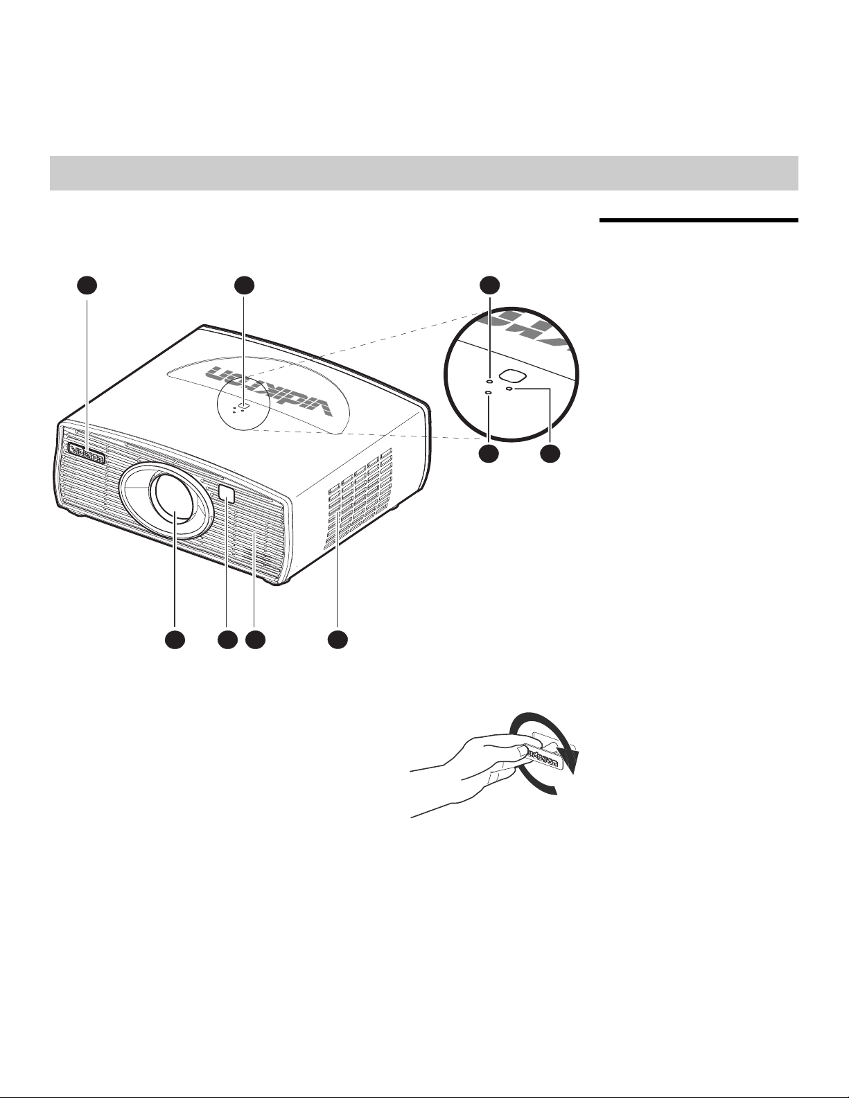
Figure 2-1 and Figure 2-2 show the key Vision 70 components.
12
IMINAR
L
2.1 Vision 70 at a Glance
3
Y
4 5
6789
Figure 2-1. Vision 70 Front/Side/Top View
PRE
1. VIDIKR
The logo can be rotated to match
orientation: inverted (ceiling-mounted) or upright.
To rotate the logo, grip it at the sides, pull it away
from the projector and rotate it 180 degrees.
2. T
3. LA
Indicates lamp status as follows:
• Off during normal operation
• Red when the lamp has exceeded its usage life or developed a problem.
• Flashes red when the fans are not working or the lamp cover is open
4. PO
Indicates power status as follows:
• Orange when the projector is in standby mode
• Flashes orange for 45 seconds after the projector is turned on to indicate that the lamp
ON LOGO
the projector
OP IR SENSOR
MP LED
WER/STANDBY LED
is warming up
Vidikron Vision 70 Series Owner’s Operating Manual 5
Controls and Functions
• Green during normal operation
• Flashes green for 110 seconds after the projector
is cooling down
5. TEMP L
Indicates fan status and internal temperature as follows:
• Off during normal operation
• Red when internal temperature is too high
• Flashes red when the fans are not working or the lamp cover is open
6. INT
ED
AKE VENT
is turned off to indicate that the lamp
7. EXHA
8. FRONT IR SENSOR
9. PROJEC
UST VENT
TION LENS
IMINAR
L
PRE
Y
4321
5
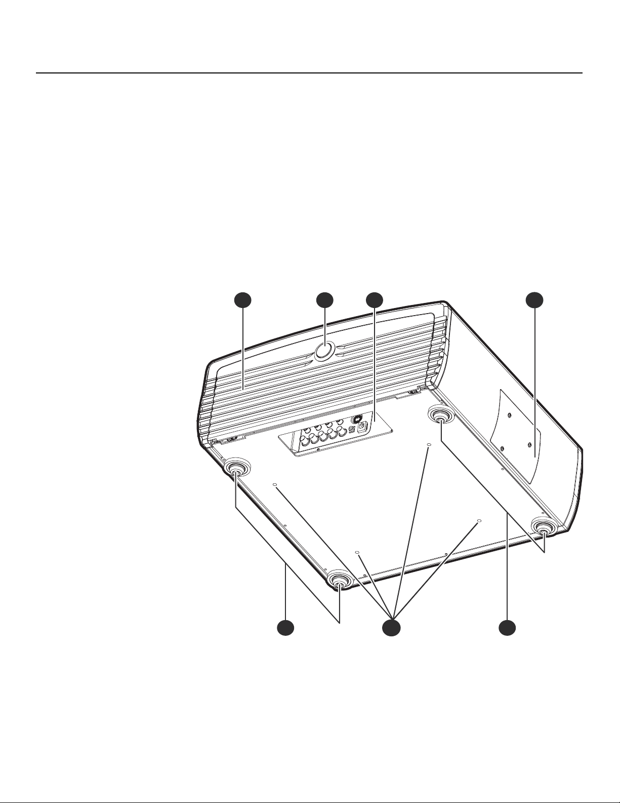
Figure 2-2. Vision 70 Rear/Bottom/Side View
6 Vidikron Vision 70 Series Owner’s Operating Manual
65
1. CABLE ACCESS DOOR
Open to access connectors.
2. DOOR RELEA
ABLE OPENING
3. C
Pass cables through this opening.
MP MODULE COVER
4. LA
Remove this cover to access the
ONT/REAR ADJUSTERS
5. FR
Use these to adjust the projector height or projection angle.
SE BUTTON
lamp compartment.
Controls and Functions
6. CEILI
To access the connector panel, press
the door release button so it pops out.
Turn the knob clockwise or
counter-clockwise and pull gently on it
to open the door.
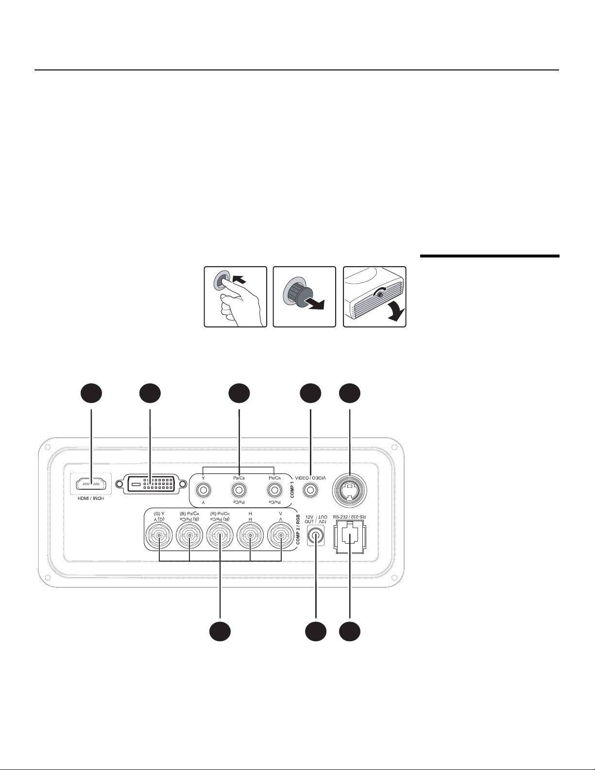
Figure 2-3 shows the Vision 70 connector panel.
NG MOUNT HOLES
Use these to attach the ceiling
1 2 3 4 5
bracket to the projector.
PRE
Y
IMINAR
L
S-VID
S-VID /
2.2 Vision 70 Connector Panel
Figure 2-3. Vision 70 Connector Panel
Vidikron Vision 70 Series Owner’s Operating Manual 7
678

Controls and Functions
1. HDMI (Digital)
HDCP-compliant digital video input for connecting a DVD player or HD tuner with a DVI
HDMI output.
or
or future use)
2. (F
DO NOT USE THIS CONNECTOR. Although it
like one and cannot be used as an additional video input.
OMP 1 (RCA connectors)
3. C
Standard Definition (480i/5
component video from sources such as DVD players.
76i) Component (YPrPb) input. This is the input for
looks like a DVI input, it does not function
2.3 Built-In Keypad
Tip
OMPOSITE VIDEO INPUT
4. C
Standard composite video input for connecting a VCR, laser disc player or other
composite video source.
VIDEO
5. S-
A standard S-Video input for connecting a DVD player, satellite receiver or Super VHS
S) VCR.
(S-VH
S-232 CONTROL PORT
6. R
A female, RJ-11 connector for interfacing with a PC or home theater automation/control
system.
-VOLT (250 mA) TRIGGER OUTPUT (3.5-mm, mini phono jack)
7. 12
Connection for a 12-volt trigger
screen mask or the Vidikron CineWide with AutoScope system.
8. CO
PRE
To control the projector when signals
from a remote control cannot reach it,
use the built-in keypad next to the
connector panel.
MP 2 / RGB
Five BNCs for connecting either RGB or component
signals. (The Vision 70 automatically detects the signal format.)
IMINAR
L
For best results, do not run your
-controlled device. This can be a retractable screen,
DVD player in progressive mode.
Y
(YPbPr) high-definition television
ZOOM+
ZOOM+
MENU
/EXIT
/EXIT
MENU
SOURCE
/ENTER
POWER
/ENTER
SOURCE
POWER
Because the built-in
keys than the remote keypad, certain
projector functions are accessible only
through the menu system rather than via
a direct key.
keypad has fewer
8 Vidikron Vision 70 Series Owner’s Operating Manual
ZOOM-
ZOOM-
MEMORY
LENS
SHIFT
MEMORY
SHIFT
LENS
Controls and Functions
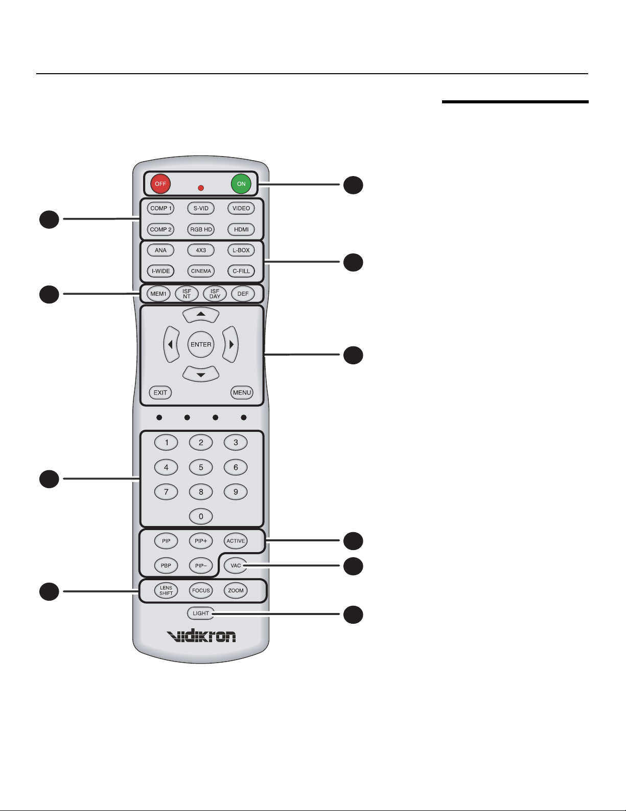
Figure 2-4 shows the Vision 70 remote control, and the paragraphs that follow describe its
functionality.
1
2
3
4
5
IMINAR
2.4 Vision 70 Remote Control
Y
6
PRE
9
Figure 2-4. Vision 70 Remote Control
L
7
8
10
Vidikron Vision 70 Series Owner’s Operating Manual 9

Controls and Functions
1. ON / OFF
Use these buttons to turn th
ource Selection Buttons:
2. S
COMP 1 (SD Component)
Press to select Component 1 (SD 480i/576i) video input
S-VID (S-Video)
Press to select the S-Video input as the source.
VIDEO
Press to select Composite video input
COMP 2 (HD Component)
Press to select Component 2
RGB HD
Press to select the Component 2 RGB input.
HDMI
Press to select the HDMI input.
e projector on or off.
as the source.
(HD 480p/576p/720p/1080i) video input as the source.
as the source.
Y
3. Aspec
PRE
t Ratio Selection Buttons
Use these buttons to select an aspect ratio directly, as follows:
ANA (Anamorphic)
For viewing 16:9 DVDs or HDTV programs in their
4X3 (Standard 4:3)
Scales the input signal to fit 4:3 displ
L-BOX (Letterbox)
For viewing LaserDisc movies or non-an
I-WIDE (IntelliWide)
Enlarges a 4:3 image horizontally in a NON-linear fashion to fit 16:9 full screen display.
CINEMA
For viewing 2.35:1 sour
C-FILL (CineWide-equipped projectors only)
Selects the Cinema Fill aspect ratio, used for viewing 16:9 source material on a 2.35:1
screen.
IMINAR
L
native aspect ratio.
ay mode in the center of the screen.
amorphic DVDs on a 4:3 screen.
ce material.
10 Vidikron Vision 70 Series Owner’s Operating Manual

4. Memory Preset Buttons:
MEM1
Press to recall settings for the current input from the “Custom
ISF NT
Press to recall settings for the current input from the “ISF
ISF DAY
Press to recall settings for the current input from the “ISF
DEF
Press to recall the factory-default
rsor Keys ( , , , )
5. Cu
Use these buttons to select items or settings, adjust setting
EXIT
Press to save menu item setting(s), exit the c
ENTER
Press to select a highlighted menu item or confirm a
MENU
Press this button to show or hide the on-screen display (OSD) controls.
settings for the current input.
urrent menu and return to the previous one.
Night” memory preset.
Day” memory preset.
s or switch display patterns.
changed setting.
Controls and Functions
1” memory preset.
Y
6. 0 -
7. Pi
8. VA
9
Use these keys to enter menu passcodes.
cture-In-Picture (PIP) / Picture-By-Picture (PBP) Controls:
PIP
Press to activate PIP mode.
PIP+
Press to enlarge the PIP window.
ACTIVE
Press to switch to the active
PBP
Press to activate PBP mode.
PIP-
Press to shrink the size
C ( V2 Aperture Control)
Adjusts the lens aperture (iris) sett
area.
PRE
window in PIP or PBP mode.
of the PIP window.
ing according to the ambient light level in the viewing
L
IMINAR
Vidikron Vision 70 Series Owner’s Operating Manual 11
Controls and Functions
2.5
Remote Control/Built-In Keypad Functional Comparison
9. Motorized Lens Controls:
LENS SHIFT
Press to access the lens shift controls.
FOCUS
Press to focus the image.
ZOOM
Press to reduce or enlarge the projected image size.
10. LIGHT
Press to illuminate the buttons.
Y
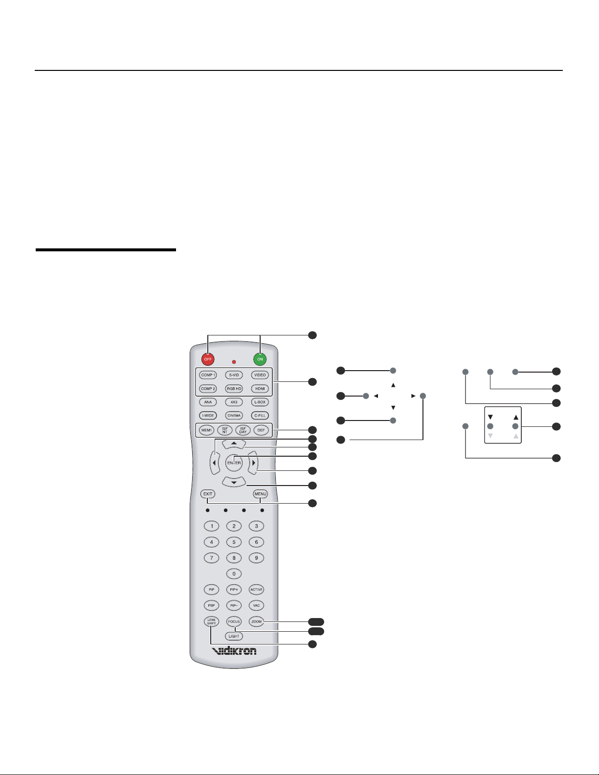
Figure 2-5 shows remote control buttons that are duplicated on the built-in keypad.
Some functions such as power ON/OFF are combine
however, the function is the same. This user manual describes the functions based on the
remote control.
d in one button on the built-in keypad;
IMINAR
L
PRE
1
SOURCE
FOCUS+
MENU
/EXIT
MEMORY
/EXIT
MENU
/ENTER
MEMORY
/ENTER
SOURCE
LENS
SHIFT
POWER
SHIFT
LENS
POWER
1
2
3
4
5
FOCUS-
ZOOM+
ZOOM+
FOCUS+
FOCUS-
ZOOM-
ZOOM-
9
2
8
7
5
8
6
9
2
6
7
3
7/9
6/8
4
Figure 2-5. Remote Control/Built-In
12 Vidikron Vision 70 Series Owner’s Operating Manual
Keypad Functional Cross-Reference
3Installation
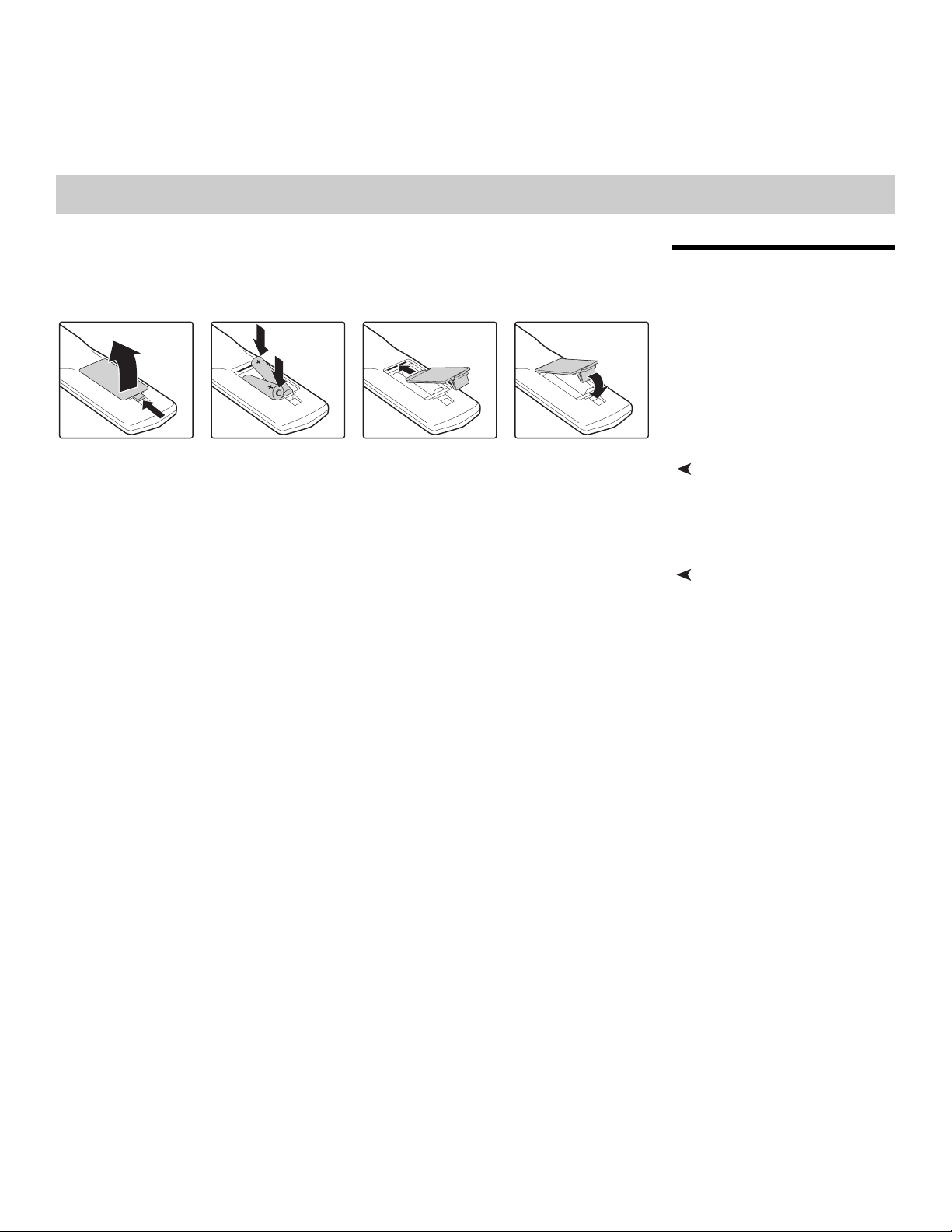
To install batteries in the remote control, push the battery cover and slide it off. Install the
two AAA batteries with the correct polarity and then replace the cover.
correct when installing the batteries.
• Do not mix an old battery with a new one or different types of batteries.
• If you will not use the remote control for a long time, remove t
damage from battery leakage.
• Make sure that there is nothing obst
control and the IR receiver on the projector.
• If the effective range of the remote control decreases, or it stops working, replace the
ba
tteries with new ones.
• The remote control may fail to operate if the inf
sunlight or fluorescent lighting.
• Ambient conditions may possibly impede the operation of the remote control. If this
h
appens, point the remote control at the projector, and repeat the operation.
• The Ø icon appears on the screen when you press a button for an unavailable function.
ructing the infrared beam between the remote
IMINAR
L
rared remote sensor is exposed to bright
he batteries to avoid
3.1 Remote Control
Y
Notes on Batteries• Make sure that the battery polarities are
Notes on Remote Control Operation
PRE
Vidikron Vision 70 Series Owner’s Operating Manual 13

Installation
3.2
Quick Setup
Table 3-1 gives a quick overview of the Vision 70 installation process. The sections following
this one provide detailed instructions.
Note
Table 3-1. Installation Overview
Step Procedure
Choose a location for the projector 15
1
If installing a Vision 70/CineWide or Vision 70/CineWide
AutoScope: Install fixed CineWide base plate or
with
2
AutoScope lens motor (optional)
Mount the projector 23
3
Connect signal sources to the Vision 70 24
4
Connect external controller to RS-232
5
Connect 12-volt trigger output to
6
other equipment (optional)
L
Apply power to the projector 30
7
Installation should be performed by a qualified custom video installation
specialist.
For Details, Refer to
Y
port (optional) 28
IMINAR
AutoScope lens motor or
19
29
page...
Change the OSD Language (optional) 31
8
For rear-screen and/or ceiling-mount
9
proper picture orientation
PRE
Primary lens adjustments: projected image size (zoom),
10
pos
ition (shift) and focus
Install CineWide anamorphic lens (optional) 32
11
CineWide lens adjustments: position, pitch (angle), geometry
12
and foc
Projector calibration: adjust the following for each in
starting with Component 1; save settings when finished:
• Aspect ratio
• Brightness
13
• Contrast
• Color level
• Tint
• Input position
us
installations, select the
put,
31
17, 31
37
49 through 55
14 Vidikron Vision 70 Series Owner’s Operating Manual

Installation
Proper installation of your projector will ensure the quality of your display. Whether you are
installing a projector temporarily or permanently, you should take the following into account
to ensure your projector performs optimally.
eds: front or rear screen, floor mount or
inverted mount. Table 3-2 compares these various installation methods.
Table 3-2. Projector Installation Options
Advantages Considerations
Front Screen, Floor Mount Installation
• Easy to set up
• Can be moved or changed quickly
• Easy to access
Front Screen, Inverted Mount (ceiling) Installation
• Does not take up audience space
• Projector is unobtrusive
• Projector cannot be accidentally moved
Rear Screen, Floor Mount Installation
• Projector is completely hidden
• Projector is easily accessed
• Usually good ambient light rejection
Rear Screen, Inverted Mount (ceiling) Installation
• Shares floor space with audience
• Installation is more permanent
• Projector access is more difficult
• Requires separate room
• Installation cost is usually higher
IMINAR
L
Y
3.3 Installation Considerations
Installation TypeChoose the installation type that best suits your ne
• Projector is completely hidden
• Usually good ambient light rejection
Rear Screen, Floor Mount with Mirror
• Projector is completely hidden
• Usually good ambient light rejection
• Requires less space behind screen than other
rear screen ins
s will be noticeably reduced if light directly strikes the screen, such as when a shaft of
image
light from a window or floodlight falls on the image. Images may then appear washed out
and less vibrant.
tallations
PRE
• Requires separate room
• Installation cost is usually higher
• Requires separate room
• Installation cost is usually higher
Ambient LightIn general, minimize or eliminate light sources directed at the screen. Contrast ratio in your
Vidikron Vision 70 Series Owner’s Operating Manual 15
 Loading...