

Vidikron 30 Owners manual

O W N E R ’ S O P E R A T I N G M A N U A L
DLP™ PROJECTOR
30
VERSION 1.0


Warranty ...................................................................................................5
Table of Contents
Safety Precautions ....................................................................................
Overview ...................................................................................................
Features ..................................................................................................................................................... 9
Front / Top View .......................................................................................................................................
Rear / Bottom View .................................................................................................................................
8
9
10
11
Controls and Functions ............................................................................ 13
Control Panel ............................................................................................................................................ 13
Connector Panel ......................................................................................................................................
Built-In Control Panel .............................................................................................................................
Vidikron Logo ...........................................................................................................................................
Remote Control ........................................................................................................................................
Control Panel / Remote Control Functions Compared ................................................................
14
14
15
15
17
Installation ................................................................................................19
Remote Control ........................................................................................................................................ 19
Installation Considerations ...................................................................................................................
20
Connections ..............................................................................................25
Connecting Video Inputs ...................................................................................................................... 25
Connecting a Computer (GBRHV) .......................................................................................................
Connecting an HDMI™ Device .............................................................................................................
Connecting to AC Power .......................................................................................................................
27
27
28
Basic Operation ........................................................................................29
Removing the Lens Cap ......................................................................................................................... 29
Turning on the Power .............................................................................................................................
Adjusting the Zoom and Focus ...........................................................................................................
Adjusting Projector Height or Projection Angle .............................................................................
Selecting Video Memory .......................................................................................................................
Selecting an Aspect Ratio .....................................................................................................................
Using the Menus ......................................................................................................................................
Selecting the Input Source ...................................................................................................................
PIP / PBP Function ...................................................................................................................................
Turning off the Power ............................................................................................................................
29
29
29
30
30
31
31
31
32
On-Screen Display Menus ........................................................................ 33
Using the Menu ....................................................................................................................................... 33
Main Menu ................................................................................................................................................
Picture Quality Adjustments ................................................................................................................
Image Options .........................................................................................................................................
Projector Status .......................................................................................................................................
33
34
36
39
Vidikron Vision Model 30 Owner’s Operating Manual
3

Table of Contents (continued)
Installation ................................................................................................................................................ 40
Service ........................................................................................................................................................
ISF Calibration ..........................................................................................................................................
Lamp Replacement ...................................................................................47
41
45
Troubleshooting .......................................................................................
RS-232 Setup ............................................................................................
Connecting RS-232 to the Projector .................................................................................................. 51
RS-232C Control Codes ..........................................................................................................................
49
51
52
Specifications ........................................................................................... 55
Dimensions ...............................................................................................
57
4
Vidikron Vision Model 30 Owner’s Operating Manual

Warranty
TWO YEAR LIMITED WARRANTY
For Projectors, Video Processors and Controllers
Congratulations on your purchase of a Vidikron video product and welcome to the Vidikron family! With proper installation,
setup and care, you should enjoy many years of unparalleled video performance.
This is a LIMITED WARRANTY as defined in the Magnuson-Moss Warranty Act. Please read it carefully and retain it with your
other important documents.
WHAT IS COVERED UNDER THE TERMS OF THIS LIMITED WARRANTY:
SERVICE LABOR: Vidikron will pay for service labor by a Vidikron Authorized Service Center when needed as a result of
manufacturing defect for a period of two (2) years from the effective date of delivery to the end user (excluding the lamp).
PARTS: (Not including the lamp) Vidikron will provide new or rebuilt replacement parts for the parts that fail due to defects in
materials or workmanship for a period of two (2) years from the effective date of delivery to the end user. Such replacement
parts are then subsequently warranted for the remaining portion (if any) of the original warranty period.
PROJECTOR LAMP: Vidikron will pay for service labor by a Vidikron Authorized Service Center when needed as a result of a
manufacturing defect for a period of six (6) months or 1000 hours, which ever comes first, from the effective date of delivery
to the end user. In addition, Vidikron will provide a new or rebuilt replacement lamp for the lamp that fails due to defects
in materials or workmanship for a period of six (6) months or 1000 hours, which ever comes first, from the effective date of
delivery to the end user. Such replacement lamps are then subsequently warranted for the remaining portion (if any) of the
original warranty period.
WHAT IS NOT COVERED UNDER THE TERMS OF THIS LIMITED WARRANTY:
This Limited Warranty only covers failure due to defects in materials and workmanship that occur during normal use and
does not cover normal maintenance. This Limited Warranty does not cover cabinets or any appearance items; failure resulting
from accident, misuse, abuse, neglect, mishandling, misapplication, faulty or improper installation or setup adjustments;
improper maintenance, alteration, improper use of any input signal; damage due to lightning or power line surges, spikes and
brownouts; damage that occurs during shipping or transit; or damage that is attributed to acts of God. In the case of remote
control units, damage resulting from leaking, old, damaged or improper batteries is also excluded from coverage under this
Limited Warranty.
CAUTION: THIS LIMITED WARRANTY ONLY COVERS VIDIKRON PRODUCTS PURCHASED FROM VIDIKRON AUTHORIZED DEALERS.
ALL OTHER PRODUCTS ARE SPECIFICALLY EXCLUDED FROM COVERAGE UNDER THIS LIMITED WARRANTY. MOREOVER, DAMAGE
RESULTING DIRECTLY OR INDIRECTLY FROM IMPROPER INSTALLATION OR SETUP IS SPECIFICALLY EXCLUDED FROM COVERAGE
UNDER THIS LIMITED WARRANTY.
Vidikron Vision Model 30 Owner’s Operating Manual
5

RIGHTS, LIMITS AND EXCLUSIONS:
Vidikron limits its obligations under any implied warranties under state laws to a period not to exceed the warranty period. There
are no express warranties. Vidikron also excludes any obligation on its part for incidental or consequential damages related to
the failure of this product to function properly. Some states do not allow limitations on how long an implied warranty lasts,
and some states do not allow the exclusion or limitation of incidental or consequential damages. So the above limitations or
exclusions may not apply to you. This warranty gives you specific legal rights, and you may also have other rights that vary
from state to state.
EFFECTIVE WARRANTY DATE:
This warranty begins on the effective date of delivery to the end user. For your convenience, keep the original bill of sale as
evidence of the purchase date.
IMPORTANT: WARRANTY REGISTRATION:
Please fill out and mail your warranty registration card. It is imperative that Vidikron knows how to reach you promptly if we
should discover a safety problem or product update for which you must be notified.
CONTACT A VIDIKRON AUTHORIZED SERVICE CENTER TO OBTAIN SERVICE:
Repairs made under the terms of this Limited Warranty covering your Vidikron video product will be performed at the location
of the product, during usual working hours, providing location of product is within normal operating distance from a Vidikron
Authorized Service Center. In some instances it may be necessary for the product to be returned to the Vidikron factory for repairs.
If, solely in Vidikron’s judgment, location of product to be repaired is beyond normal operating distance of the closest Vidikron
Authorized Service Center, or the repair requires the unit be returned to the Vidikron factory, it is the owner’s responsibility
to arrange for shipment of the product for repair. These arrangements must be made through the selling Vidikron Dealer. If
this is not possible, contact Vidikron directly for a Return Authorization number and shipping instructions. Vidikron will return
product transportation prepaid in the United States, unless no product defect is discovered. In that instance, shipping costs
will be the responsibility of the owner.
COPYRIGHT AND TRADEMARKS
© Copyright 2005 Vidikron. This document contains proprietary information protected by copyright. All rights are reserved.
No part of this manual may be reproduced by any mechanical, electronic or other means, in any form, without prior written
permission of the manufacturer.
All trademarks and registered trademarks are the property of their respective owners.
6
Vidikron Vision Model 30 Owner’s Operating Manual

ADDITIONAL INFORMATION:
To locate the name and address of the nearest Vidikron Authorized Service Center, or for additional information about this
Limited Warranty, please call or write:
VIDIKRON
Attn: Customer Service Department
2900 Faber Street
Union City, CA 94587
Ph: (510) 324-5900
Fax: (510) 324-5905
Toll Free: (888)
4VIDIKRON
VIDIKRON PRODUCT INFORMATION
RETAIN THIS INFORMATION FOR YOUR RECORDS
Model Purchased Date
Serial Number
Vidikron Authorized Dealer Name
Address
City State/Province Postal Code
Phone Fax
Vidikron Vision Model 30 Owner’s Operating Manual
7
Safety Precautions
CAUTION
RISK O F ELECT RIC SHO CK
DO NOT O PE
N
CAUTION:
TO REDUCE THE RISK OF ELECTRIC SHOCK
DO NOT REMOVE COVER (OR BACK)
NO USER SERVICEABLE PARTS INSIDE.
REFER SERVICING TO QUALIFIED
SERVICE PERSONNEL.
Thank you for your purchase of this quality Vidikron video projector! It has been designed
to provide you with the quality of video that is expected in a home theater. For the best
performance, please read this manual carefully as it is your guide through the menus and
operation.
WARNING
This symbol is intended to alert the user to the presence of uninsulated “dangerous voltage”
within the product’s enclosure that may be of sufficient magnitude to constitute a risk of
electric shock.
This symbol is intended to alert the user to the presence of important operating and
maintenance (servicing) instructions in the literature accompanying the appliance.
This equipment has been tested and found to comply with the limits for a Class B digital
device, pursuant to Part 15 of the FCC Rules. These limits are designed to provide reasonable
protection against harmful interference in a residential installation.
1. Read these instructions.
2. Keep these instructions.
3. Heed all warnings.
4. Do not use this projector near water, outdoors or otherwise exposed to the
elements.
5. Clean only with a dry cloth.
6. Do not block any ventilation openings.
7. Do not install near any heat sources such as radiators, heat registers, stoves, or
other apparatus (including amplifiers) that produce heat.
8. Do not defeat the safety feature of the polarized or grounding type plug. A polarized
type plug has two blades with one wider than the other. A grounding type plug has
two blades and a third grounding prong. The third prong is provided for your
safety. If the provided plug does not fit into your outlet, consult an electrician for
the replacement of the obsolete outlet.
9. Do not connect the RJ-11 RS-232 jack to a telephone line connection.
10. The 12V trigger only outputs DC 12V signal for triggering. Do not connect to any
other power input or output. This could cause damage to this unit.
11. Only use accessories specified by Vidikron.
12. Keep the packing material in case the projector should ever need to be shipped.
13. Unplug this projector during lightning storms or when it will not be used for an
extended period of time.
14. The lamp becomes extremely hot during operation. Allow the projector to cool down
for approximately 45 minutes prior to removing the lamp assembly for replacement.
Do not operate lamps beyond the rated lamp life. Excessive operation of lamps
beyond rated life could cause them to explode in rare occasions.
15. Refer all servicing to qualified service personnel. Servicing is required when the
projector has been damaged in any way, objects have fallen or spilled into the
projector, the projector has been exposed to rain or moisture, does not operate
normally, or has been dropped.
8
Vidikron Vision Model 30 Owner’s Operating Manual

Overview
• Native 16:9 Aspect Ratio DMD 1280 x 720p
• High Contrast and Picture Quality
12-degree mirrors with dark metal process.
• High Dynamic Range and Rich Gray-scale
6-segment, 5x color wheel with wide color space.
• TIR (Total Internal Reflection) Prism
High-performance light engine with Cat’s Eye optics.
• Wide Variety of Inputs
Support for various video formats, including Composite, S-Video, Component, DT V
Y/PB/PR, DTV RGB HD and Computer signals. The HDTV input (DTV Y/PB/PR and DTV
RGB) is via RGB BNC connectors, providing the least amount of signal degradation
caused by longer cable runs.
• HDTV Ready
480p, 1080i and 720p (576p PAL Version) formats are all compatible with this unit
(via an external DTV decoder, not provided).
Features
• De-interlacing with 3:2 Pull-down
Using Vidikron’s proprietary De-interlacing technology, this projector provides
exceptional scaling and film-to-video (3:2 pulldown) conversion for the most artifact free images possible.
• PIP/ PBP function
Picture in Picture/Picture by Picture functions allow you to display two inputs
on the screen at the same time.
• ISF Calibration
This product includes ISF day and night mode settings as established by the
Imaging Science Foundation. These standards provide for superior image quality
and assure the user that restoration to preset values for both day and night viewing
is accomplished by just the press of a button, should the projector’s settings or
calibrations be inadvertently disturbed.
Vidikron Vision Model 30 Owner’s Operating Manual
9

Overview
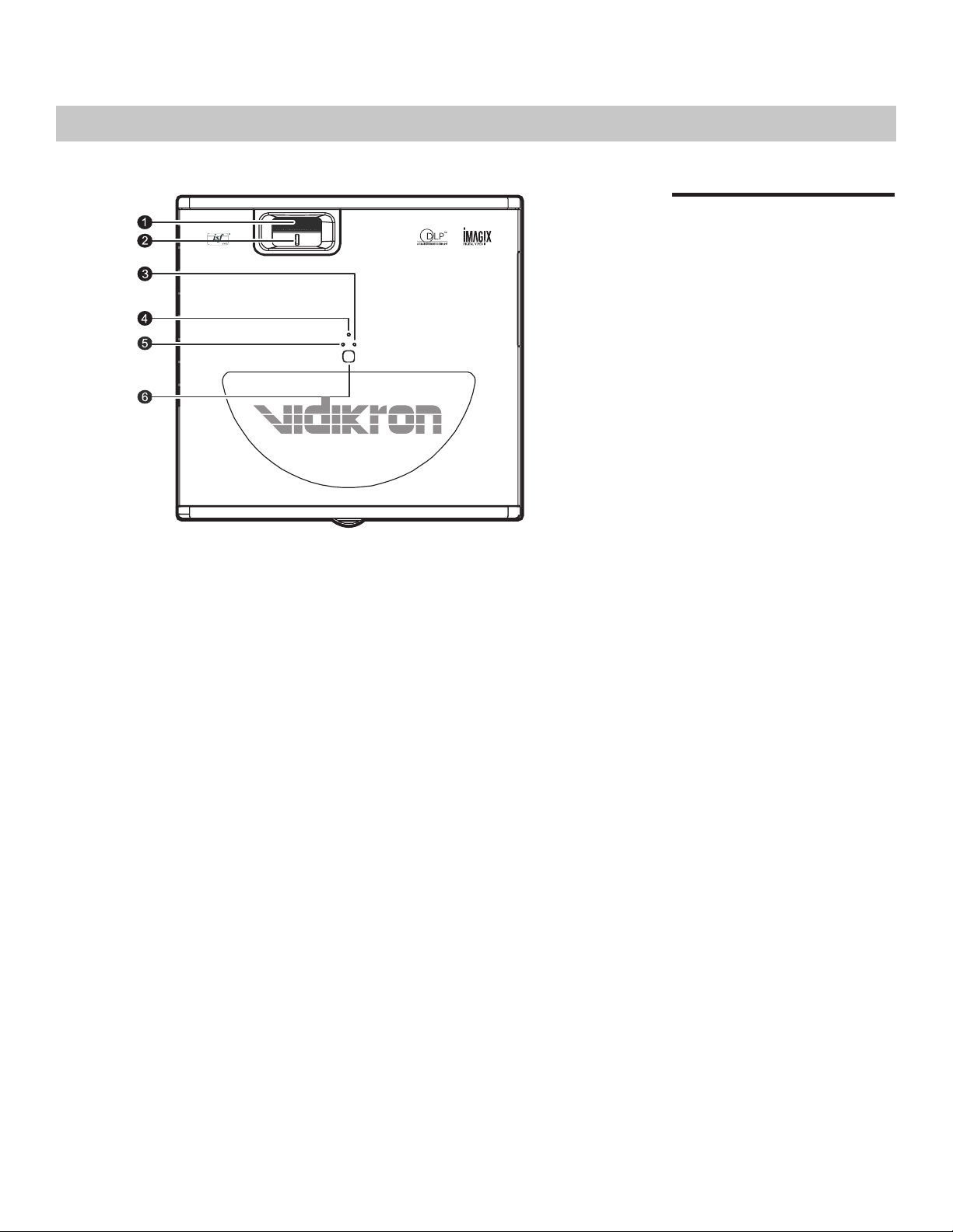
Front / Top View
1. Exhaust Vent
2. Focus Ring and Zoom Ring Access
Adjust the focus and zoom of image.
3. Top IR Sensor
4. Status LEDs
See “Control Panel” on page 13.
5. Intake Vent
6. Front IR Sensor
7. Vidikron Logo
Can be rotated to match floor or
ceiling installation. See “Vidikron
Logo” on page 15.
8. Projection Lens
10
Vidikron Vision Model 30 Owner’s Operating Manual
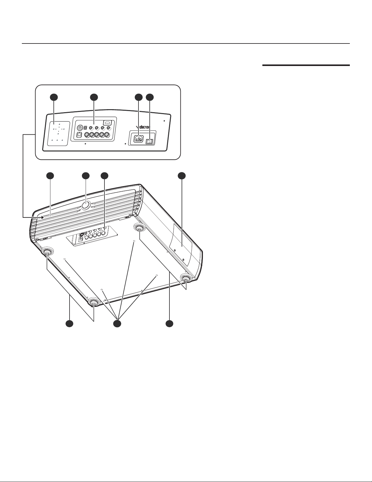
Rear / Bottom View
MEMORY
MEMORY
AUTO
AUTO
POWER
POWER
MENU
/EXIT
MENU
/EXIT
SOURCE
/ENTER
SOURCE
/ENTER
1 2 3 4
8765
9 10 9
Overview
1. Built-in Control Panel
See “Built-in Control Panel” on
page 14.
2. Connector Panel
See “Connector Panel” on page 14.
3. AC Power IN Socket
4. AC Power Switch
5. Cable Access Door
Open to access connectors.
See “Connector Panel” on page 14.
6. Door Release Button
7. Cable Opening
Pass cables through this opening.
8. Lamp Module Cover
Remove this cover when replacing
the lamp. See “Lamp Replacement”
on page 47.
9. Front / Rear Adjusters
Adjusts the height or projection
angle.
10. Ceiling Mount Holes
The connecting holes for the ceiling
mount bracket.
Vidikron Vision Model 30 Owner’s Operating Manual
11

Overview
This page is intentionally left blank.
12
Vidikron Vision Model 30 Owner’s Operating Manual
Controls and Functions
Control Panel
1. FOCUS RING
Adjust the focus of the image
- Rotate the focus ring right or left to
focus the image.
2. ZOOM RING
Adjust the size of the image
- Rotate right to enlarge the image.
- Rotate left to reduce the image.
3. LAMP LED
Indicates the status of the lamp
- Red when the lamp has exceeded
its usage life or developed a problem.
Please contact your Vidikron Dealer
for assistance.
- Flashing Red when the fans are
not working or the lamp cover is
open. Please contact your Vidikron
Dealer for assistance.
4. POWER LED
Indicates the status of the power
- Orange when the AC power cord
is plugged into a wall outlet (standby
mode). Once in standby mode, you
can turn on the projector by
pressing the ON button on the
remote control.
- Green when the power is turned
on (operational mode).
- Flashing Orange for the first 45
seconds after power-up indicating
that the lamp is warming up.
- Flashing Green for 110 seconds
after the projector was powered off
indicating that the lamp is cooling
down.
5. TEMP LED
Indicates the status of the fans and
internal temperature
- Red when the internal temperature
is too high. Please contact your
Vidikron Dealer for assistance.
- Flashing Red when the fans are
not working or the lamp cover is
open. Please contact your Vidikron
Dealer for assistance.
6. TOP IR SENSOR
Vidikron Vision Model 30 Owner’s Operating Manual
13
Controls and Functions
MEMORY
MEMORY
AUTO
AUTO
POWER
POWER
MENU
/EXIT
MENU
/EXIT
SOURCE
/ENTER
SOURCE
/ENTER
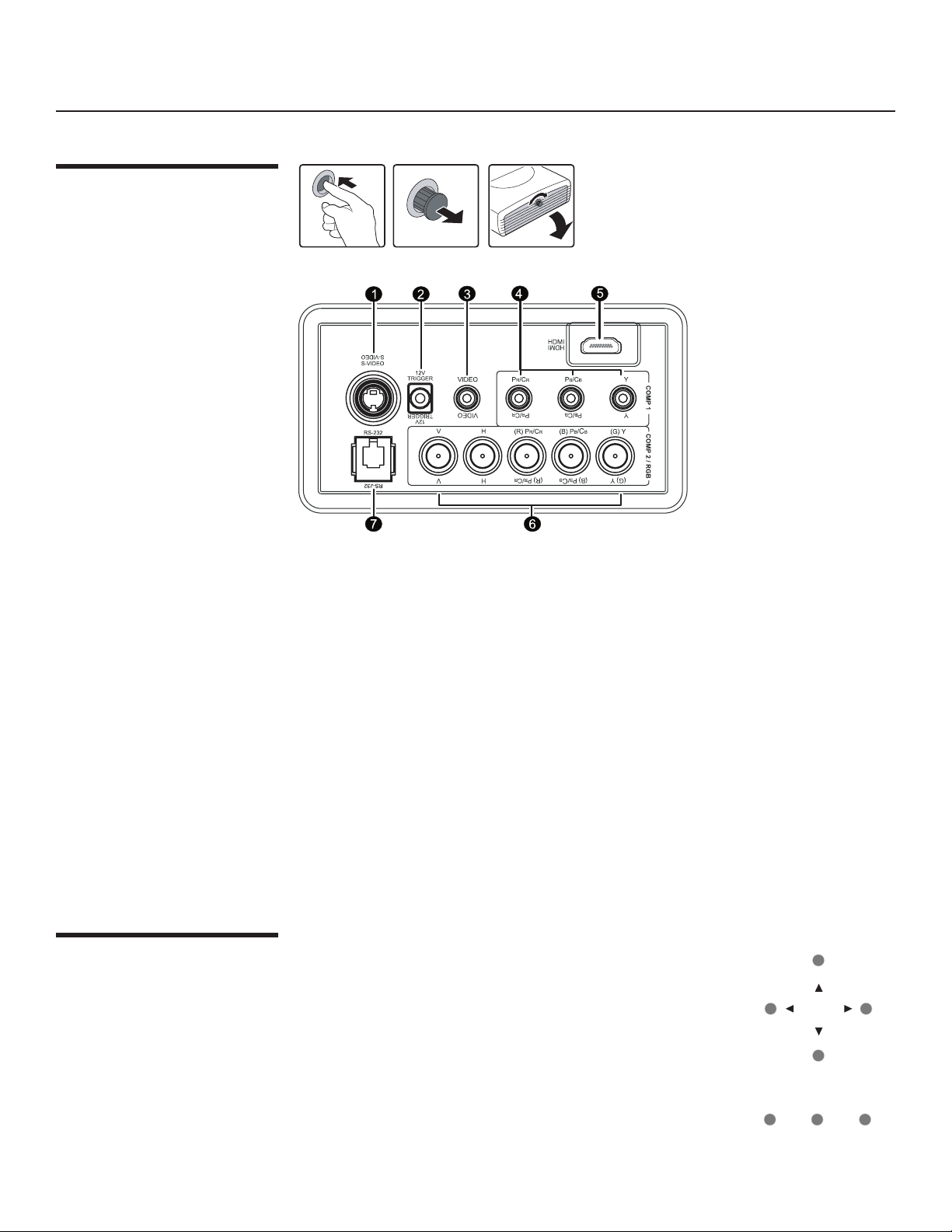
Connector Panel
To access the connector panel, press the
door release button so it pops out. Turn
the knob clockwise or counter-clockwise
and pull firmly on it to open the door.
1. S-Video (mini DIN 4-pin) Y/C (S-video) signal input
2. 12v Trigger (mini jack, diameter 5.5 mm outside, 2.5 mm inside)
+12V output, active when the projector is turned on
Built-In Control Panel
3. Video (RCA Jack)
Composite video signal input
4. Component (RCA Jacks)
480i Component (Y/CB/CR) video signal input
5. HDMI (High-Definition Multimedia Interface) Input
Digital video signal input
6. RGB/ HDTV (BNC) or Progressive Scan DVD players
DTV Y/P
B/PR or DTV RGB video signal input
7. RS-232C (RJ-11 Jack)
RS-232C control signal input (refer to page 51 for details)
To control the projector when signals from a remote control
cannot reach it, use the built-in keypad next to the connector
panel.
Because the built-in keypad has fewer keys than the remote
keypad, certain projector functions are accessible only through
the menu system rather than via a direct key.
14
Vidikron Vision Model 30 Owner’s Operating Manual
EXIT
L-BOX
I-WIDE
CINEMA
C-FILL
MEM1
ISF
NT
ISF
DAY
DEF
1
2
3
4
5
6
7 8
9
0
PIP PIP+
PIP-
ACTIVE
PBP
VAC
LIGHT
MENU
ON
OFF
COMP 1
COMP 2
S-VID
VIDEO
RGB HD
HDMI
ANA
4X3
Controls and Functions
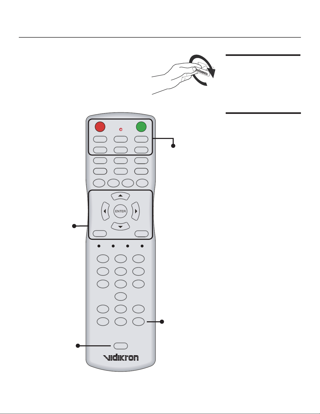
The Vidikron logo on the front of the projector can
be rotated to match a floor or ceiling installation. To
rotate the logo, grip it at the sides, pull it away from
the projector and rotate it 180 degrees.
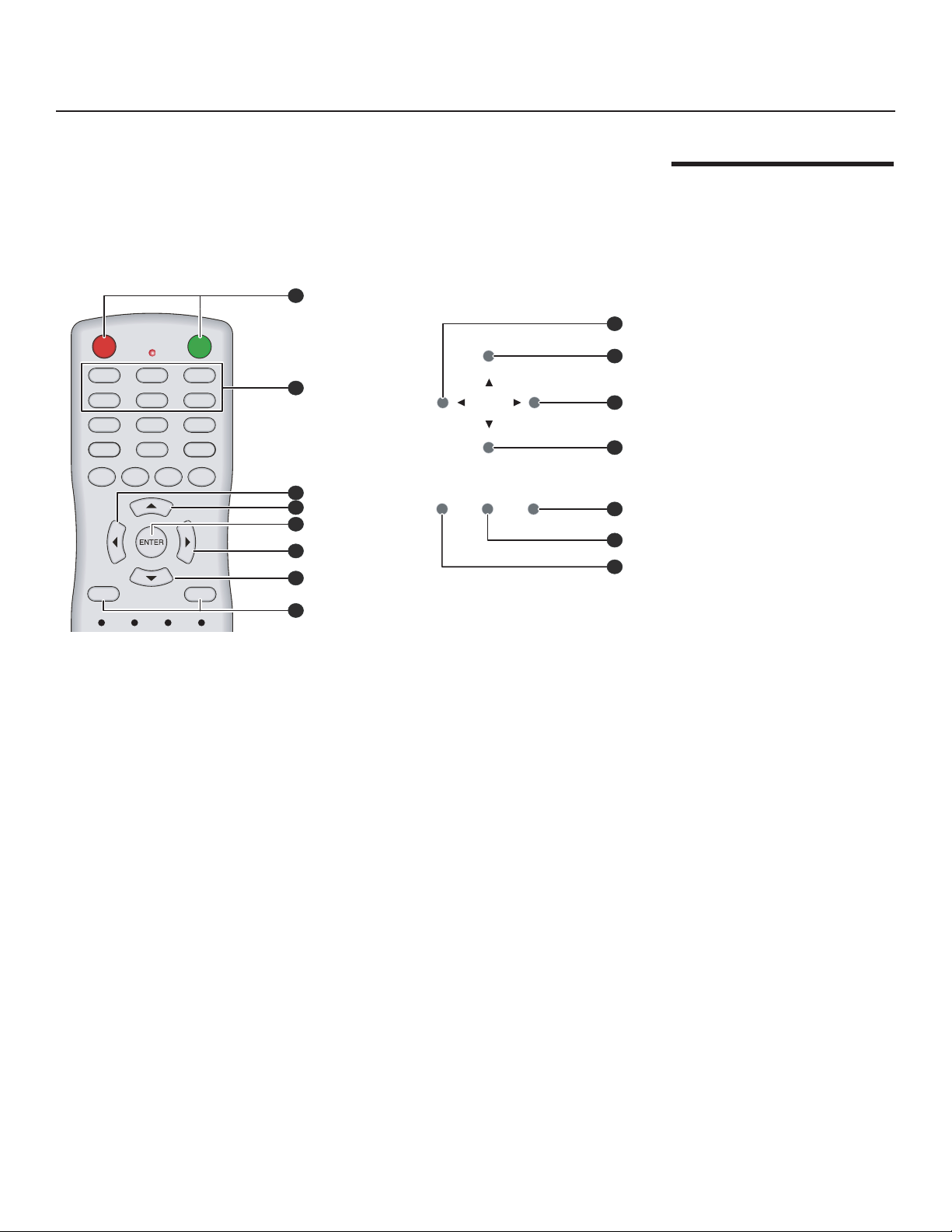
Arrow (▲,◄,▼,►)
Use to select the menu or to
make various adjustments.
ENTER
Enter the setting of items in
the menu.
EXIT
Exit and save the setting(s) of
items in the menu.
MENU
Turns the on-screen display
menu on or off.
Vidikron Logo
Remote Control
OFF
Press to turn off the
projector.
ON
Press to turn on the
projector.
COMP1 (Component 1)
Component Y/CB/CR input.
S-VID (S-Video)
S-Video signal input.
VIDEO
Composite video signal
input.
COMP2 (Component 2)
DTV Y/PB/PR signal input.
RGB HD
DTV RGBHV signal input.
HDMI
High-Definition Multimedia
Input.
LIGHT
Press to turn on the remote
control back light.
Vidikron Vision Model 30 Owner’s Operating Manual
VAC
Not applicable to this
model.
15
EXIT
L-BOX
I-WIDE
CINEMA
C-FILL
MEM1
ISF
NT
ISF
DAY
DEF
1
2
3
4
5
6
7 8
9
0
PIP PIP+
PIP-
ACTIVE
PBP
VAC
LIGHT
MENU
ON
OFF
COMP 1
COMP 2
S-VID
VIDEO
RGB HD
HDMI
ANA
4X3
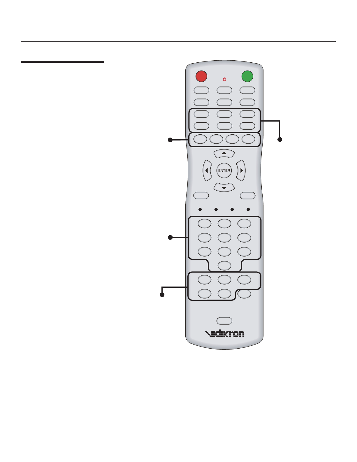
Controls and Functions
Remote Control
(continued)
MEM1, ISF NT (Night),
ISF DAY, DEF
Recall video memory
sequentially. See
“Selecting Video
Memory” on page 30.
0 - 9
Press to type in menu
passcodes.
ANA (Anamorphic)
For 16:9 DVDs.
4X3 (Standard 4:3)
The input signal will be scaled
to fit 4:3 display mode in the
center of the screen.
L-BOX (Letterbox)
Image in letterbox format is
enlarged to fit 16:9 full screen
display and the upper/ lower
portions are “blanked off.”
I-WIDE (IntelliWide)
4:3 image is enlarged NONlinearly in horizontal direction
to fit 16:9 full screen display.
CINEMA
Image in Letterbox mode is
enlarged to a 16x9 image and
the upper and lower por tions
are compressed.
PIP (Picture in Picture) Enable
the PIP function. Use the arrow
buttons to adjust the position
of the PIP window. See “PIP /
PBP Function” on page 31.
PIP+
Enlarge the size of PIP window.
ACTIVE
Switch to the active window in
PIP display mode.
PBP (Picture by Picture)
Enable the PBP function.
PIP-
Shrink the size of the PIP
window.
16
C-FILL (Cinema Fill)
A 2.35 image is stretched
vertically in both directions to
fill a 16:9 image.
Vidikron Vision Model 30 Owner’s Operating Manual
EXIT
L-BOX
I-WIDE
CINEMA
C-FILL
MEM1
ISF
NT
ISF
DAY
DEF
MENU
ON
OFF
COMP 1
COMP 2
S-VID
VIDEO
RGB HD
HDMI
ANA
4X3
MEMORY
AUTO
POWER
MENU
/EXIT
SOURCE
/ENTER
1
2
3
4
5
6
7
7
1
2
5
3
4
6
5
Controls and Functions
The following illustration shows remote control buttons that are duplicated on the control
panel. Some of the functions such as power ON/OFF are combined in one button on the
control panel, however, the function is the same. This user manual describes the functions
based on the remote control.
Control Panel / Remote Control Functions Compared
Vidikron Vision Model 30 Owner’s Operating Manual
17

Controls and Functions
This page is intentionally left blank.
18
Vidikron Vision Model 30 Owner’s Operating Manual
 Loading...